KAVAN V20 - Changing the mode: Difference between revisions
No edit summary Tag: Manual revert |
(Marked this version for translation) |
||
| Line 42: | Line 42: | ||
# Screws on the outer side of the strip (3, 7) set the ratcheting. | # Screws on the outer side of the strip (3, 7) set the ratcheting. | ||
<!--T:6--> | |||
=== Video tutorial === | === Video tutorial === | ||
If you're not feeling confident enough after reading these steps, please follow our video tutorial. | If you're not feeling confident enough after reading these steps, please follow our video tutorial. | ||
<!--T:7--> | |||
<html><iframe width="560" height="315" src="https://www.youtube.com/embed/yZzQqn0d0Tk?si=7VDW9TQWUV5LOCpt" title="YouTube video player" frameborder="0" allow="accelerometer; autoplay; clipboard-write; encrypted-media; gyroscope; picture-in-picture; web-share" referrerpolicy="strict-origin-when-cross-origin" allowfullscreen></iframe></html> | <html><iframe width="560" height="315" src="https://www.youtube.com/embed/yZzQqn0d0Tk?si=7VDW9TQWUV5LOCpt" title="YouTube video player" frameborder="0" allow="accelerometer; autoplay; clipboard-write; encrypted-media; gyroscope; picture-in-picture; web-share" referrerpolicy="strict-origin-when-cross-origin" allowfullscreen></iframe></html> | ||
</translate> | </translate> | ||
Revision as of 13:23, 14 May 2024
Introduction
Changing the flight mode is simple and fast if you follow the correct procedure. Please refer to the steps below to change the flight mode of your transmitter, or if you want to set the feedback of the sticks.
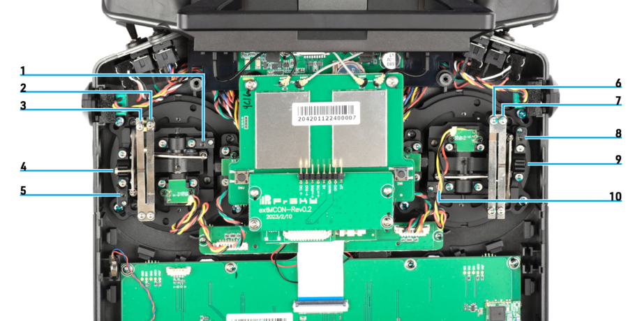
Description
- Horizontal centring tension spring - right gimbal
- Ratcheting adjustment screw - right gimbal
- Brake/resistance adjustment screw - right gimbal
- Centring spring lock
- Vertical centring tension spring - right gimbal
- Ratcheting adjustment screw - left gimbal
- Brake/resistance adjustment screw - left gimbal
- Vertical centring tension spring - left gimbal
- Hole for the centring spring lock
- Horizontal centring tension spring - left gimbal
Steps
- Remove the battery compartment cover.
- Unplug and remove the battery from the battery compartment.
- Holding the handle in your hands carefully remove the rear cover. Be careful not to pull the antennas.
- Rotate and flip the rear cover to make some space.
- Unscrew the centring spring lock from the current throttle stick.
- On the current throttle side tighten the vertical tension spring counterclockwise so the stick centres.
- On the opposite side loosen the vertical tension spring clockwise.
- Lift the centring arm a little and insert and screw in the centring spring lock on the new throttle stick side.
- Set the feedback of both gimbals to your preference via the steps below.
- Put the rear cover back in place.
- Screw in the 4 screws on the rear cover.
- Plug in and insert the transmitter battery in the battery tray.
- Put the battery tray cover on.
Setting the gimbal feedback
- Screws on the inner side of the strip (2, 6) set the gimbal tension.
- Screws on the outer side of the strip (3, 7) set the ratcheting.
Video tutorial
If you're not feeling confident enough after reading these steps, please follow our video tutorial.
