Translations:KAVAN Bristell B23 1600mm - Instruction manual/17/en
- Trial the fit of the horizontal and vertical tailplane and the fuselage - no glue yet (Fig. 2+3). Double-check the parts fit tight and the fin is vertical to the horizontal stabilizer (Fig. 4). If necessary, sand the parts to fit.
- Connect the rudder servo to the extension cable in the fuselage (RUDD) and secure the connectors with a piece of heat shrink tube, bind them together with dental floss or secure them with a strip of sticky tape. Apply medium or rather thick cyano (or clear silicone or MS polymer glue) to the contact area of the fin and attach the fin to the fuselage. (Fig. 2)
- Connect the elevator servo to the extension cable in the fuselage (ELEV) and secure the connectors with a piece of heat shrink tube, bind them together with dental floss or secure them with a strip of sticky tape. Apply medium or rather thick cyano (or clear silicone or MS polymer glue) to the contact area of the horizontal tailplane assembly and attach it to the fuselage. (Fig. 3)
- Before the glue sets, double-check the fin is vertical to the horizontal stabilizer. (Fig. 4)
- Slide the wing halves onto the wing tube joiner; arrange the aileron and flap servo cables and the LED light cables onto the upper side of the wing. (Fig. 5)
- Thread the servo and LED light cables into the cockpit and attach the wing to the fuselage. Attach the main undercarriage to the bottom of the wing and secure it together with the wing to the fuselage using two 3.0×40 mm bolts. (Fig. 6)
- Insert the nose gear into the bracket in the fuselage and remove the canopy. Slide the nose gear arm onto the nose gear wire and secure it with an M3.0×10 mm setting screw. (Fig. 7+8+9)
- Attach the propeller to the prop driver and secure it with the propeller nut with a washer. (For your safety, leave the propeller installation after your radio is all connected and set and the correct direction of rotation of your motor has been tested.) Secure the spinner using an M2.5×22 mm bolt in place. (Fig. 10)
- Attach a strip of a hook–and–loop (the loop part, not supplied in the kit) to the bottom of your flight pack and secure it with the hook–and–loop fasteners to the battery seat in the cockpit. (Fig. 11)
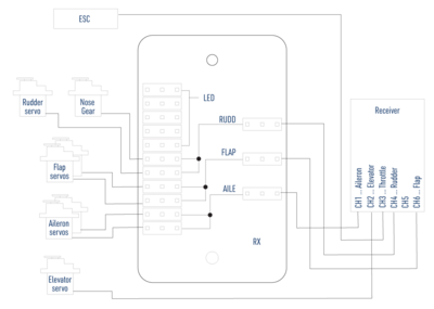
B23 - Receiver connection - Remove the connection board cover and hook up your receiver, servos and ESC following the wiring diagram right. The receiver is to be secured with a strip of double-sided foam tape or hook–and–loop tape to the rear part of the cockpit. Deploy the antennas, so their active parts are square to each other (if you are using a receiver featuring diversity antennas).Note: The kit is supplied with the connection board for ailerons, flaps, rudder and the steerable nose gear, so you can use even the most basic 6-channel radios to control your Bristell B23. If you intend to use independent control of aileron and flap servos and an advanced computer radio, you will have to replace the default Y-cables with four 25–30 cm extension cables.
The LED lights are only powered via the connection board. They are not remotely controlled in any way. - With your radio on, set the servos to the neutral position (sticks and trims centred) and fasten the setting screws of the pushrod connectors on the elevator and rudder servo arms. Perform the throttle range calibration of the ESC as described in the attachment of this manual.
- Attach the canopy.
- Use medium cyano to glue the dummy antennas (Fig. 13) and pitot tube. (Fig. 14)
