Regler KAVAN Smart PRO SBEC - Bedienungsanleitung
Einleitung
Intelligente programmierbare elektronische Drehzahlregler für Brushless-Motoren
Herzlichen Glückwunsch zum Kauf des Drehzahlreglers für Brushless-Motoren KAVAN Smart PRO. Die Produktreihe KAVAN Smart PRO stellt fortschrittliche Drehzahlregler für Brushless-Motoren für den ausschließlichen Einsatz in RC-Flugzeugmodellen vor. Mit integrierter Telemetrie und verschiedenen Möglichkeiten der Benutzerkonfiguration bieten die Regler hohe Effizienz, geringes Gewicht und präzise Motorsteuerung. Das integrierte leistungsstarke BEC sichert einen Dauerausgangsstrom von bis zu 15 A und ist selbst für anspruchsvollste Anwendungen geeignet. Die volle Leistung der BEC-Schaltung ist bei jeder Batteriespannung innerhalb der Reglerspezifikation (6-51V) verfügbar.
Funktionen
- Geringe Größe kombiniert mit hoher Leistung für die Motorsteuerung.
- Das leistungsstarke BEC bietet einen Dauerstrom von bis zu 15 A (max. 30 A). Überstrom- und Überhitzungsschutz sind integriert.
- BEC-Spannungseinstellung in 0,1-V-Schritten.
- Über- und Unterspannungsschutz, Überhitzungsschutz, Motorblockierschutz.
- Konfigurierbare Strombegrenzung.
- Schneller und präziser Heli/Governor-Modus mit vielen Einstellmöglichkeiten.
- Sicherheitsabschaltung des Motors bei Verlust des Gasimpulses.
- Konfigurierbare Beschleunigung, Timing, elektromagnetische Bremse, Motorumkehr usw.
- Geringe Geräuschentwicklung durch Hochfrequenzschaltung.
- Automatische Telemetrie: FPort, konfigurierbar über Lua-Script. Alternative Firmware Duplex EX, Hott, MSB, PowerBox P²Bus, S.Bus2, Spektrum SRXL2.
- Telemetrie (abhängig von der RC-Anlage): Spannung, Strom, Leistung, Kapazität, Temperatur, Drehzahl, Energie.
- Minimal- und Maximalwerte der Telemetrie werden aufgezeichnet.
- Konfiguration über den Sender, PC-Software MAV Manager oder externes Terminal (JETIBOX/SMART-BOX).
- Firmware-Updates mit USB-Interface.
- Sprachen: CZ/DE/EN/FR/IT.
| ESC-65 | ESC-85 | ESC-115 rev. 2024 | ESC-115 ACRO | ESC-145 | ESC-145 | ESC-155 rev. 2024 | |
|---|---|---|---|---|---|---|---|
| Abmessungen (mm) | 75×29.5×10 | 75×29.5×12 | 80×30×13.5 | 88×32×14 | 88×32×20 | 74×53×31 | 88×32×14 |
| Gewicht inkl. Kabel (g) | 63 | 68 | 81 | 100 | 125 | 190 | 100 |
| Dauerstrom (A) | 50* | 60* | 80* | 110* | 110* | 140* | 150* |
| Spitzenstrom (A/2s) | 80* | 100* | 120* | 170* | 170* | 200* | 200* |
| Versorgungsspannung (V) | 6–51 | 6–51 | 6–51 | 6–51 | 6–51 | 10–51 | 6–27 |
| LiPo-Zellen | 2–12 | 2–12 | 2–12 | 2–12 | 2–12 | 4–12 | 2–6 |
| LiFe-Zellen | 3–14 | 3–14 | 3–14 | 3–14 | 3–14 | 4–14 | 3–7 |
| Kabel
Batterie/Motor (mm²) |
2.5 /
2.5 |
2.5 /
2.5 |
4 /
2.5 |
4 /
4 |
4 /
4 |
6 /
4 |
6 /
4 |
| Antispark Schaltung | Nein | ||||||
| Empfohlene
Stecker |
XT60 (60A) | XT60 (60A) | G4 (75A),
XT90 (90A) |
G5.5,
XT90 (90A) |
G5.5,
XT90 (90A) |
G5.5 (150A) | G5.5 (150A) |
| Temperaturbereich (°C) | (-10)–110 | ||||||
| PWM Frequenz (kHz) | 20 | ||||||
| Betriebsstrom (mA) | 60 | ||||||
| Standby-Strom (mA) | 4 | ||||||
| Positionierung der Luftschraube | Nein | Mit zusätzlichem Hall-Sensor | |||||
| Telemetrie | Duplex EX, Multiplex MSB, Futaba S.Bus2, Graupner Hott, PowerBox P2Bus, Spektrum SRXL2™ | ||||||
| Status-LED | Ja | ||||||
| Aktive Bremse
(freewheeling) |
Ja | ||||||
| Dauer-Ausgangsstrom
BEC (A) |
12* | 15* | |||||
| Spitzenstrom BEC (A/2s) | 25* | 30* | |||||
| Spannungseinstellung
BEC (V) |
5.5–8.4 (0,1-V-Schritte) | ||||||
| Optische Isolation | Nein | ||||||
| Maximale Drehzahl (eRPM) | > 300 000 (zweipoliger Motor) | ||||||
| Spannung des externen Schalters (V) | ca. 10 | ||||||
| Strom des externen Schalters (mA) | Max. 30 | ||||||
*) Diese Werte sind gültig, wenn ein ausreichender kontinuierlicher Luftstrom gewährleistet ist.
Installation
Befestigen Sie den Regler mit Klettband oder doppelseitigem Klebeband in Ihrem Modell. Schließen Sie den Motor und den Empfänger gemäß dem unten stehenden Diagramm an. Sie können die Motorkabel in beliebiger Reihenfolge anschließen, da die Drehrichtungsänderung durch Vertauschen eines der beiden Kabel erfolgt (oder auch durch den Parameter „Richtung“ in der Konfiguration). Schalten Sie den Sender ein. Nun können Sie die Hauptflugbatterie anschließen und den Regler mit dem angeschlossenen Empfänger einschalten.
Verwenden Sie immer ganz neue, hochwertige Stecker und achten Sie darauf, dass die Kabel perfekt verlötet sind. Jede Möglichkeit einer Kontaktunterbrechung bei laufendem Motor bedeutet das Risiko einer Beschädigung der Elektronik.
Wenn Sie den Regler zum ersten Mal in Betrieb nehmen oder wesentliche Änderungen in den Einstellungen vornehmen, stellen Sie sicher, dass die Luftschraube von der Motorwelle entfernt ist.
Trennen Sie die Batterien nach dem Flug immer. Auch wenn der Regler mit dem Schalter ausgeschaltet ist, zieht er immer einen kleinen Strom. Dies kann dazu führen, dass die Batterie innerhalb weniger Tage oder Wochen vollständig entladen ist.Reglermodus
Es ist möglich, zwischen einigen grundlegenden Reglermodi zu wählen:
- Normal - die voreingestellte Beschleunigungskurve wird beim Beschleunigen immer verwendet. Dies ist der Standardmodus für den normalen Gebrauch.
- Schnellmodus - die vorkonfigurierte Beschleunigung wird nur beim Hochdrehen von Drehzahl Null angewendet. Danach wird die minimale mögliche Verzögerung verwendet (0,2 s für die Reaktion von Null auf Vollgas).
- Normal mit Reverse - verhält sich ähnlich wie der Normalmodus. Zusätzlich können Sie einen Gasumkehrkanal wählen, der die Motordrehrichtung während des Fluges steuert.
- Heli/Governor - schnelle und präzise Steuerung der konstanten Drehzahl mit vielen einstellbaren Parametern.
Throttle input signal
The controller expects positive impulses from the receiver with a maximum refresh rate of up to 400 Hz. By default, with automatic endpoints selected, the controller will work with the vast majority of RC systems.
In this case, a minimum throttle signal pulse is loaded after start-up. The maximum power is then dynamically adjusted when you first give full throttle.
In case you need exact points on your transmitter stick, where the motor starts and where the full throttle is, you can configure manual endpoints as well.
Motor settings
It is possible to configure many of the motor parameters, including acceleration, timing, motor gear ratio or number of poles. The gear ratio and number of poles are important for telemetry to measure the motor speed correctly.
Acceleration influences the motor response on the throttle channel. By decreasing the acceleration value, the motor response gets faster, providing a more "locked-in" feeling. However, the motor consumes more current and the controller generates more heat. We recommend the default acceleration of 1.0 s for the majority of model types, including electric gliders, scale models, EDFs etc. For 3D aerobatic flight, you might go down to 0.5 s or even less (with care). For the fastest motor response, you may also set the "Fast controller mode" in the Common Settings.
Timing is defined by the motor type and it is usually recommended by the motor manufacturer. It also influences the motor power and current consumption. Higher timing can increase the motor power but care must be taken not to overload the system.
- Automatic timing: the timing is continuously adjusted by the internal algorithm. This is a universal solution compatible with most motor types.
- 0–10° timing: recommended for inrunners, i.e. motors with internal magnets.
- 15–20° timing: recommended for most outrunners (motors with rotating casing). It offers a good combination of power and efficiency.
- 25–30° timing: high-torque motors with many poles require the highest timing.
The motor type should be modified only in some specific cases where it is necessary by the application.
There are three options available:
- "Standard" motor type - recommended for most types and applications (default).
- "High Torque" - if you have problems with motor synchronization during fast acceleration, use this mode. Preconditions: large outrunner with more than 20 poles, heavy propeller, large current peaks. We also recommend increasing the timing to more than 20°.
- "High speed" - use this mode if your drive unit exceeds 250,000 eRPM (revolutions per minute calculated for a 2-pole motor).
Startup power influences the first few motor revolutions. If you are not satisfied with the automatic mode, you can set the motor start to be more aggressive (positive values), or as smooth as possible (negative values).
Brake configuration
The electromagnetic brake is a standard feature of all ESCs used in electric glider models. The KAVAN Smart PRO controller offers several additional parameters to fine-tune the braking function. You can use one of the preconfigured brake settings or specify all the parameters as you wish.
- Off: The propeller spins freely without braking.
- Soft: Transition from zero to full braking force in 1.0 s.
- Medium: Transition to full braking force in 0.7 s.
- Hard: Transition from 50% to 100% braking force in 0.5 s.
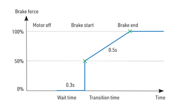
- Manual: you can specify all brake parameters manually:
- Start power (start of brake) - braking force applied from the first moment of applying the brake.
- End power (end of brake) - braking force applied after the transition time elapses (usually the full braking force that stops the motor completely).
- Transition - the time between brake start power and brake end power. During this time, the braking force continuously transits from start to end power.
- Wait time - the time between unpowering the motor and applying the brake. During this time the motor spins freely without power.
Example: motor brake with the following parameters: brake start = 50%, brake end = 100%, ramp = 0.5 s, wait time = 0.3 s.
BEC voltage and settings
In the Common Setting menu, you can modify the BEC voltage very precisely in steps of 0.1 V. The controller contains a very powerful BEC which can deliver up to 15 A continuous current. However, in case of a high-power setup, sufficient cooling airflow must be provided. Connecting both Telemetry and Throttle cables to the receiver is recommended to provide high current throughput.
Backup battery
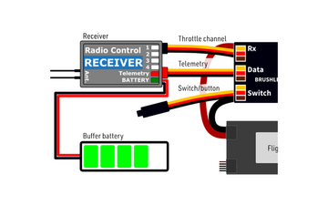
In case you need a small buffer battery for covering voltage spikes of the attached servos, you can specify its presence in the Common Setting – Backup battery menu. After setting the battery type it is necessary to remove all power supplies from the controller and then reconnect them. Possible options:
- "No" (default) - the buffer battery is not present and the BEC voltage is set according to the value set in the configuration. No external power supply shall be connected to the receiver side, otherwise the BEC won’t turn on.
- "2S LiPo 8.4V" - an external power supply with a maximum voltage of 8.4 V is expected on the receiver side (see the picture). The controller won’t initialise itself if the backup battery voltage is outside the limits (or not connected). The BEC voltage will be set automatically according to the backup battery so that there is no risk of uncontrolled currents.
- "2S LiFe 7.2V" - an external power supply with a maximum voltage of 7.2 V is expected on the receiver side. The behaviour is similar to the case of 2S LiPo.
External switch
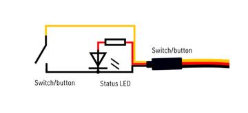
The KAVAN Smart PRO ESC allows you to install an external switch if needed. By default, the switch is not present so the speed controller/BEC turns on immediately after connecting the flight battery.
You can specify the type of switching element in the Common Setting – Switch Type:
- Mechanical (default) - the switch shorts the yellow (signal) and brown (ground) wires of the Switch/Button cable. An inverted logic is used, so that the ESC stays turned on if the switch is left open.
- Button/Hall - the first long press turns on the ESC; the second long press turns it off. The LED indicates an on/off state and blinks if the magnet (or button press) is detected. The Hall sensor can be bought as an ESC accessory.
- Electronic - allows you to install an external electronic switch (Touch Switch, RC Switch etc.). In this case, the switching device is always powered and the logic level of the signal wire specifies the on/off state to the controller.
Propeller positioning
The positioning feature allows moving the motor/propeller to the exact position required for a safe landing, or which is just comfortable for further flying. With just a few external components (a Hall sensor and a small magnet) you can enable this feature and prevent the risk of damaging your propeller during landing. The magnet needs to be properly fixed to the rotating part (either the motor or the propeller), and the Hall sensor has to be located in the fuselage so that the magnet matches the Hall sensor at the target propeller position. After enabling the positioning feature in the menu (Prop Position = Hall Sensor), set also the Positioning PWM, so that the motor spins slowly but smoothly. You may also change the duration of the actively held motor position (Position Hold Time) which is applied after the correct position is found. The position-hold feature is useful in the case of a retractable engine since it doesn’t allow the propeller to be moved while retracting.
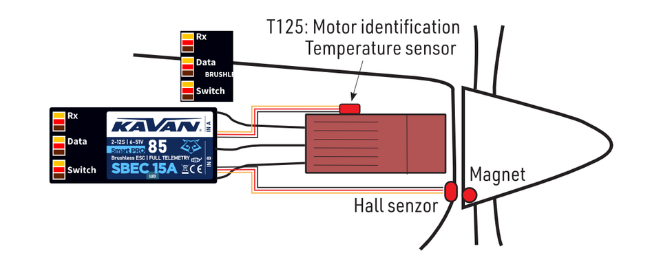
Connect the Hall sensor of the propeller positioning function to the IN-B port of the controller.
Motor identification
Some motor brands contain an integrated temperature sensor compatible with the KAVAN Smart PRO speed controller. This sensor (T125-ID) might be used as a standalone telemetry sensor with Duplex/Hott/S.Bus2 telemetry support. Alternatively, the sensor can be directly connected to the Input port "A" of the controller (see the picture above). From this moment on, the KAVAN Smart PRO controller will know the basic motor parameters (minimum acceleration, recommended timing, gear ratio, number of poles…) and motor temperature as well. Some parameters are adjusted automatically (gear ratio, poles), and the other settings are configured after resetting the controller to factory defaults. Connect the motor-identification sensor into the IN-A port of the controller.
Active freewheeling
"Active freewheeling" or "Active braking" is a feature of the speed controller that reduces heat generated by the ESC during partial load operation. This mode is useful for aerobatic pilots who want not only fast acceleration but also rapid deceleration. The motor follows throttle stick input in both ways and the pilot feels more "locked-in".
Current limiter
The current limiter is a part of safety controller features. It doesn’t stop the motor but rather continuously monitors the immediate current consumption and adjusts the motor power. You can enable this feature, specify the maximum allowed current and the ESC will reduce the motor power immediately as soon as the current threshold is exceeded. After the current returns back to the safe level, the motor power is restored.
Battery protection
The integrated battery protection is based on undervoltage detection and reducing motor power, alternatively shutting down the motor completely. You can freely set the number of cells (or leave automatic detection) and low voltage threshold per cell. Supported battery types are NiXX (1.2 V), LiFe (3.6 V max) and LiIo/LiPo (4.2 V max).
Status codes
The status codes are shown on the screen (JETIBOX/SMART-BOX) if any kind of error condition occurs. If any status code is set, the red LED continuously flashes.
Available status codes:
- Low Voltage (UL): the battery voltage got below the threshold specified in the battery protection menu and the controller either reduced the maximum power or shut down the motor completely.
- High voltage (UH): in case you use a weak battery or wall power supply, the voltage might rise above the initial level during braking. In such a case, the alarm is set and all braking functions are disabled.
- High current (IH): the current got higher than the maximum peak current defined in the product specification (120 A for KAVAN Smart PRO 85).
- High temperature (T100, T110, T120): the temperature got above the safety threshold level. The numerical value specifies the maximum detected temperature and safety protocol which has been applied.
- Commutation error (COM): a synchronization error has been detected during the motor operation. It usually occurs when the motor stops abruptly, or in case of very fast acceleration for some specific setups. This error could mean a serious issue in the motor-controller installation.
Heli/governor mode

The speed controllers contain a fast and precise governor function. You can configure the governor mode in many aspects according to your preferences.
Before enabling the governor mode, please make sure the blades are removed. In the Common Setting menu, set the Controller Mode to "Heli/Governor" and proceed through the settings below:
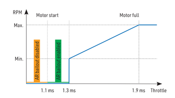
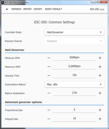
- Set the minimum and maximum RPM of the main rotor according to your preferences. As soon as you move the throttle away from the idle position, the controller slowly spools up until it reaches the target speed. The speed is calculated according to the throttle channel value, where low throttle corresponds to the "Minimum RPM" and high throttle corresponds to "Maximum RPM".
- Set the Spool-up Time to make the motor startups as smooth as possible. You may set the time up to 60s. The spool-up time is applied when the motor starts from zero
revolutions or if the autorotation bailout is disabled.
- Configure the Autorotation bailout time and autorotation acceleration time. The autorotation bailout function is used in case you need to quickly exit the autorotation and prevent your model from crashing. In this case, as soon as you move the throttle channel away from the idle position, the "Autorotation acceleration" will be used to spin the motor until it reaches the required speed. The "Autorotation bailout" parameter sets the time after switching off the motor, when the autorotation bailout function may be activated. After exceeding this time, a standard spool-up time will be applied.
- Advanced settings: Governor gains – (P)roportional and (I)ntegral. You may modify the gains to fine-tune the controller response to fast changes in the load during flight manoeuvres. Please perform the changes only in small steps and verify the resulting behaviour in a short test flight.
- Increase the P gain to eliminate small RPM fluctuations during straight flight, e.g. while hovering. If you hear some unexpected noise in the motor/gearbox (which means fast oscillations), reduce the P gain by 20 %.
- Increase the I gain to hold the precise revolutions during manoeuvres. If the motor speed starts oscillating noticeably, reduce the I gain by 20%.
- In the Governor mode, manual throttle endpoints are always used (by default 1.1–1.9 ms) and Active braking is enabled as well.
The picture below shows RPM response vs. throttle position. In this case, default throttle endpoints have been used (1.1–1.9ms).
Motor direction reversing
The motor reverse feature is available for RC systems with bidirectional bus support (EX Bus, P²Bus, SRXL2, S.Bus2). To control the motor direction you need to define an additional channel transferred through the bus system. Both cables (red and black) of the KAVAN Smart PRO speed controller must be properly linked to the receiver. First, you need to create an additional channel on your transmitter to control the motor direction. This channel should be operated by a two-position switch.
Futaba/Spektrum:
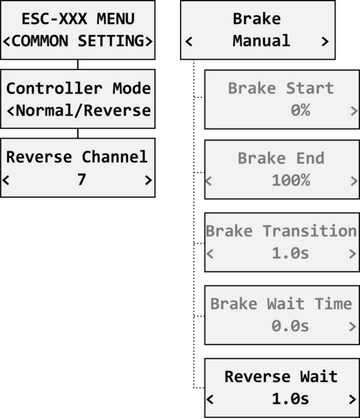
Use one of the AUX channels and remember the channel number. It is not necessary to use just the channels available on your receiver since the RC systems usually offer more channels over the bus than the physical number of receiver ports.
Example: If you use Spektrum NX6 and a 6-channel receiver, you may still use channel No. 7 (AUX2) to control the reversing feature over the bus.
JETI:
Create a new model function in the Model - Functions Assignment menu and assign a spare two-position switch. After that, in the Model – Servo Assignment menu, assign the function to one of the receiver channels (1–16). Again, you may use the channels that are not directly available on the receiver outputs (e.g. 13–16) since they will be transferred through EX Bus without limitation.
PowerBox:
Create a new model function in the Function menu by pressing the "+" button and assign it a 2-position control switch. Choose one of the available servo output channels (1–16). The switch position will be transferred over the P²Bus to the speed controller.
To enable the motor reverse function in the controller, set the "Controller Mode" to "Normal/Reverse" and set the correct channel from the previous step. You may also play with the brake settings and reverse wait time under the "Manual" brake type.
Check the function: As soon as you flip the direction switch, the controller activates braking, and after some short pause, the motor starts spinning in the opposite direction.
Telemetry and settings
Plug the red data cable into the sensor slot of the JETIBOX / SMART-BOX (or corresponding receiver). Power it up with a battery (4.5–8.4 V). Now you can safely configure the controller using the arrows on the terminal. If you use an external (optional) switch connected to the ESC, please make sure that the controller is turned on.
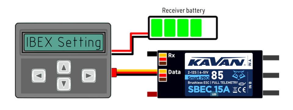
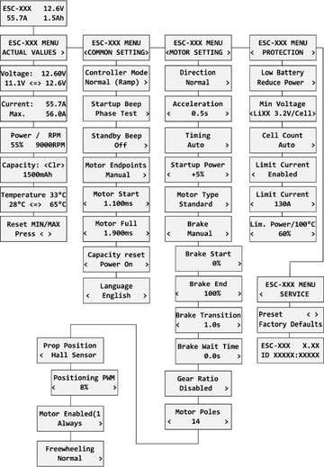
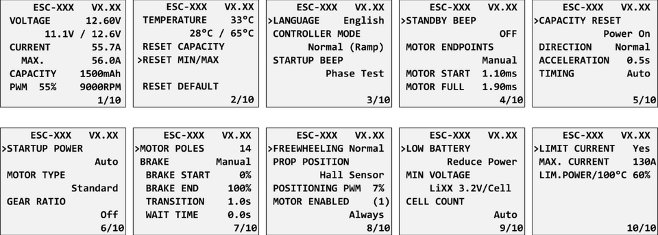
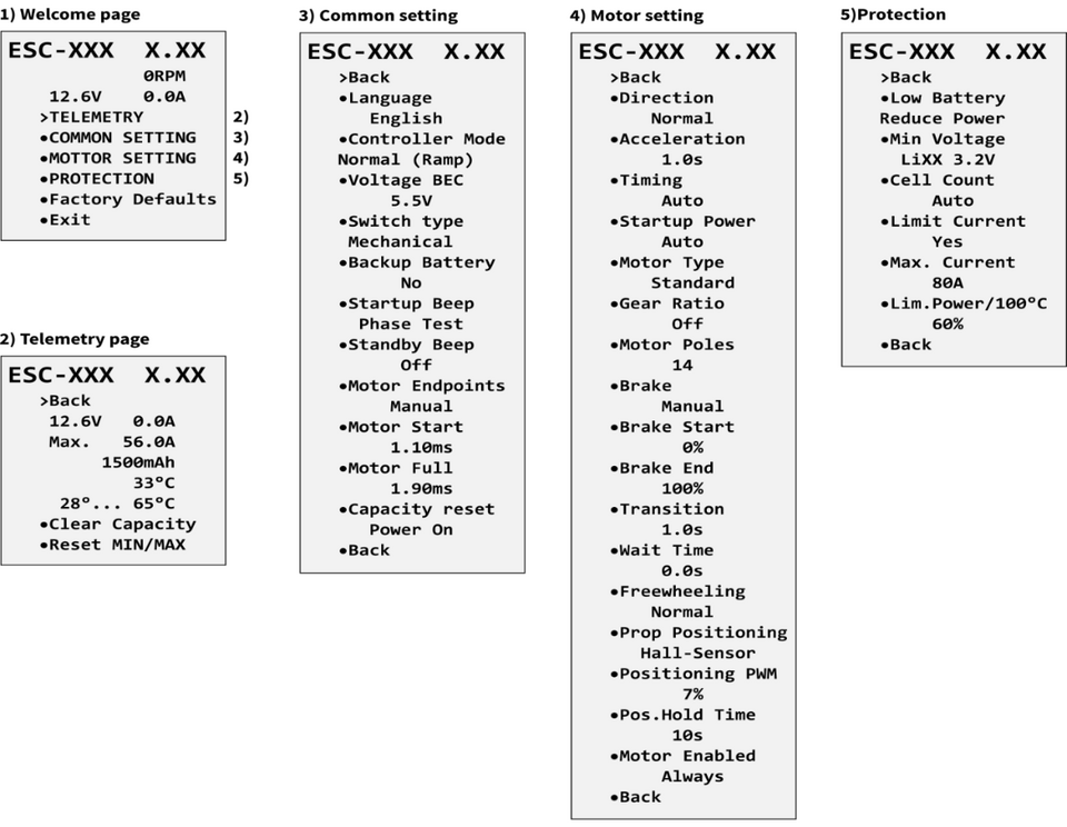
KAVAN Smart PRO controllers are compatible with JETIBOX programming. The JETIBOX menu is divided into five sections:
Actual values
- displays the latest telemetry values together with minimums and maximums.
- Available telemetry: Voltage, current, capacity, RPM, power (per cent), temperature.
- If the motor chip ID is connected, also motor identification and temperature are shown.
- Reset Min/Max - press the left and right buttons together to reset all minimums and maximums.
Common settings
- basic controller settings
- Controller mode - basic controller mode (normal or fast).
- Startup beep - choose a melody played after the controller initialization.
- Standby beep - you can activate short repeated beeps as an indication of a powered motor drive.
- Motor endpoints, motor start, motor full - settings related to throttle input signal decoding.
- Capacity reset - you can choose at which moment the capacity and consumed energy are reset:
- Power on - the capacity is reset after the controller initialization. However, the capacity from the previous run will be displayed initially until you start the engine.
- Voltage change - the capacity is cleared after you connect a battery with a similar (or greater) voltage compared to the maximum battery voltage from the previous run. This means that each time you connect a fully charged battery of the same chemistry and number of cells, the capacity will be cleared.
- Manual - the capacity/energy is never cleared and you must perform the reset manually.
- Language - you can choose the language of the JETIBOX screen.
Motor settings
- settings related to motor parameters.
- Direction, acceleration, timing, startup power, motor type, gear ratio, motor poles - see the Motor Settings chapter.
- Brake related settings - see the Brake Configuration chapter.
- Prop position, positioning PWM, position hold time - see the chapter Propeller positioning.
- Motor Enabled (0/1) - motor operation can be enabled or disabled based on the logical state of the specific input “IN B.2” (connector pinout from left to right: 1 = Hall sensor input, 2 = Motor enable input, 3 = 3.3V, 4 = Ground). If you choose an “InputPin Log0/1” option, you must pull the throttle low before starting the motor. On the other hand, after choosing the "Autostart Log0/1" option, the controller will start spinning as soon as the input pin state allows it and the throttle position is above the idle position.
- Freewheeling - enables freewheeling/active braking motor operation.
Protection
- ESC and battery protection settings.
- Low battery - behavior when the battery is discharged. Either set to slowly reduce the motor power, or shut down the motor immediately. The minimum safe voltage is based on number of cells (cell count) and voltage per cell.
- Limit current - enable this feature to prevent high current peaks and system overload.
- Limit power at 100°C - you can edit the maximum allowed PWM after the controller temperature exceeds 100 °C. The model must be operable, but the temperature must not increase anymore.
Service
- In this menu, you can view the device version and reset it to the default factory configuration.
Available EX and P²Bus telemetry:
- Battery voltage (V)
- Motor current (A)
- Capacity (mAh)
- Speed (RPM)
- PWM (%)
- Power (W)
- Motor run time (s)
- Energy (Wmin) - a useful feature for competitions where the total energy is limited (F5B, F5D).
- Temperature (°C)
- External temperature (°C) - if the motor identification chip is connected, the ESC forwards motor temperature in its own telemetry.
- Motor status:
- 0 = initial state
- 1 = motor running
- 2 = braking
- 3 = positioning started
- 4 = position found.
- 5 = position error (prop out).
- BEC voltage (V)
- BEC current (A) - KAVAN Smart PRO 145 only.
The KAVAN SMART PRO controller is recognised by default as an "Air-ESC" sensor.
Futaba and Multiplex connection
Futaba and Multiplex systems do not offer wireless device configuration. The telemetry transmission is possible with the following fixed sensor slots:
| Futaba S.Bus2 slot | Note | Slot Multiplex MSB | |
|---|---|---|---|
| Speed | 2 | Select the RPM sensor on slot 2. | 6 |
| Current | 3 | Select the SBS01C current sensor on
slot 3. |
3 |
| Voltage | 4 | 2 | |
| Capacity | 5 | 4 | |
| Temperature | 6 | Select the Temp125 sensor on slot 6. | 5 |
| PWM (0–100%) | 7 | Select the Temp125 sensor on slot 7. | - |
| Note | Manual detection in menu Linkage - Sensor. | Automatically detected by the transmitter. | |
PowerBox Telemetry
From version 1.09, the KAVAN Smart PRO controller can recognise the PowerBox P²Bus telemetry protocol. Connect the Telemetry cable (red connector) to the P²Bus port of the receiver. The transmitter scans for attached sensors as soon as the receiver is powered up and the controller telemetry should be available within 2.5 seconds. After that, you are free to assign the telemetry to any desktop widgets and alarms. Available telemetry is similar to the Duplex EX telemetry (see above). The controller configuration through the PowerBox transmitter is not available at the moment.
Spektrum Integration
From version 1.06, the Spektrum telemetry support has been integrated into a special firmware version. This alternative firmware offers the SRXL2 telemetry and setting using the TextGen protocol. The KAVAN Smart PRO controller is represented in the transmitter by two telemetry devices:
- "ESC" shows battery voltage, current, BEC voltage, ESC temperature, RPM and power output.
- "Flight Pack Capacity" sensor that shows the consumed battery capacity.
Connect the Throttle cable (black connector) to the Thr (1) receiver port. For proper telemetry/setting, also connect the Telemetry cable (red connector) to the Prog/SRXL2 receiver port. The controller normally delivers only numerical telemetry. The textual menu (TextGen) is available only after a special procedure is performed during startup:
- We assume the Throttle and Telemetry cables are connected correctly and the transmitter is turned on. Now push the throttle high.
- Turn on the ESC either by connecting the flight pack or by flipping the external switch.
- The motor will beep indicating detection of the high throttle impulse. After 3 seconds, another beep announces entering the programming menu.
- Now you may pull the throttle low. On the transmitter's main screen scroll right to locate the TextGen menu. The motor will never start spinning if the textual menu is enabled. To enable normal motor operation, you have to leave the TextGen menu by choosing the "Exit" option on the first page.
- Navigation in the menu is provided by the transmitter's sticks – the elevator stick moves the cursor up/down and the aileron stick changes the selected value.
- The configuration changes are saved immediately after any value is edited.
The KAVAN Smart PRO version 2.01 and later is compatible with Spektrum single-cable operation (Smart Throttle). To enable this function, just plug the red telemetry cable into receiver channel No.1 and keep the other (black) cable unplugged. You will be able to control throttle as well as receive telemetry. This approach is compatible with the AR10400T receiver family as well.
Safety information
- Operate the KAVAN SMART PRO controller always in a dry environment and within the device limits stated in this guide. Never expose the device to excessive heat or cold outside the working area.
- Provide sufficient airflow to prevent controller overheating.
- Never exceed the maximum allowed operating voltage of the controller/motor.
- Do not increase the cable length between the controller and the motor. If you need to extend the wires between the controller and the battery to more than 30 cm (in total), solder multiple high-capacity Low-ESR capacitors (220–470 µF) in parallel to the power wires as close to the controller as possible. For each centimetre beyond the specified cable length, add a capacitance of 1µF for every Ampere of current passing through. For example, if you exceed the limit by 10 cm with a current of 100 A, solder a 1000 µF capacitor pack.
- Always use high-quality connectors in good condition. Replace them if any visible sign of wearing appears.
- Always remove the propeller before making any changes in the drive setup.
- Never disconnect the ESC from the battery while the motor is spinning.
- Do not remove the cover and heat sink from the device, and do not try to implement any changes or modifications. This can lead to total destruction and to the denial of any warranty claims.
- Always check the polarity of the connection. Never inverse the polarity – this could lead to total destruction.
Firmware update
Firmware updates for KAVAN Smart PRO controllers are transferred from a PC via the USB interface. The required programs and files are available at www.mavsense.com.
Install the MAV Manager software and the USB drivers on your computer. Check the system requirements.
- Make sure that the flight pack is disconnected and the KAVAN Smart PRO ESC is unpowered.
- Connect the USB interface to your PC, run MAV Manager - Updater and select the correct COM Port.
- Connect the KAVAN Smart PRO ESC according to the picture below – use the red (telemetry) port. The controller will be automatically detected.
- Select the correct *.BIN file and press the Update button.

PC configuration
It is possible to use the MAV Manager software (1.4.0 and later) to conveniently configure all controller settings, display real-time telemetry and make a backup of the configuration. The configuration menu contains four buttons in the top toolbar:
- Refresh - forces the configuration to be reloaded from the controller.
- Import - imports the settings from a file. If you have several speed controllers and want identical settings for all of them, simply import the same settings to each controller.
- Export - exports the settings from the controller to a file. You can easily create a backup configuration stored on your PC. After creating a backup, you may easily experiment with the controller settings and later revert back to the original configuration by pressing the "Import" button and choosing the original exported file.
- Reset default - resets the controller to factory defaults and reloads all the settings.
Connect the controller to a computer using the USB interface. It is automatically detected by the MAV Manager.
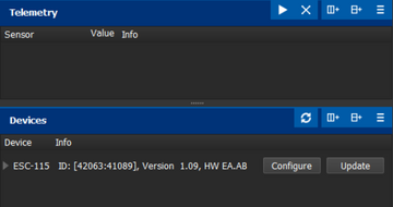
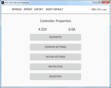
The controller properties are available by pressing the "Configure" button.
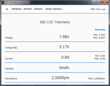
Real-time telemetry with min/max values. MAV Manager is also capable of creating a log file from real-time telemetry data that can be viewed, analyzed, imported and exported.
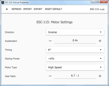
Motor Settings. Whenever a configuration change is made, the new value is immediately transferred to the controller and stored in memory. No additional confirmation is required. For safety reasons, some parameters are only applied after the motor has stopped.
Manufacturer
All KAVAN Smart PRO electronic speed controllers are made in Czechia by MAV Sense s.r.o.
E-mail: info@mavsense.com | Web: www.mavsense.com
Recycling and waste disposal note (European Union)

Electrical equipment marked with the crossed-out waste bin symbol must not be discarded in the domestic waste; it should be disposed of via the appropriate specialised disposal system. In the countries of the EU (European Union) electrical devices must not be discarded via the normal domestic waste system (WEEE - Waste of Electrical and Electronic Equipment, Directive 2012/19/EU). You can take your unwanted equipment to your nearest public collection point or recycling centre, where it will be disposed of in the proper manner at no charge to you. By disposing of your old equipment in a responsible manner you make an important contribution to the safeguarding of the environment.
EU declaration of conformity (European Union)

Hereby, KAVAN Europe s.r.o. declares that these KAVAN Smart PRO line brushless electronic speed controllers are in compliance with the essential requirements as laid down in the EU directive(s) concerning electromagnetic compatibility. The full text of the EU Declaration of Conformity is available at www.kavanrc.com/doc.
Guarantee
The KAVAN Europe s.r.o. products are covered by a guarantee that fulfils the currently valid legal requirements in your country. If you wish to make a claim under guarantee, please contact the retailer from whom you first purchased the equipment. The guarantee does not cover faults which were caused in the following ways: crashes, improper use, incorrect connection, reversed polarity, maintenance work carried out late, incorrectly or not at all, or by unauthorised personnel, use of other than genuine KAVAN Europe s.r.o. accessories, modifications or repairs which were not carried out by KAVAN Europe s.r.o. or an authorised KAVAN Europe s.r.o., accidental or deliberate damage, defects caused by normal wear and tear, operation outside the Specification, or in conjunction with equipment made by other manufacturers. Please be sure to read the appropriate information sheets in the product documentation.
