KAVAN Smart PRO Opto ESCs - Instruction manual
Introduction
Smart programmable electronic controllers for brushless motors
Congratulations on purchasing the KAVAN Smart PRO line electronic speed controller for brushless motors. The KAVAN Smart PRO product line represents advanced brushless motor controllers used exclusively in RC model aircraft. With integrated telemetry and various user configuration options, the controllers offer high efficiency, low weight and precise motor control. All the ESCs can be quickly programmed using your transmitter, PC or an external terminal.
Features
- Small size combined with high power for motor control.
- Over-voltage and under-voltage protection, over-temperature protection, motor sudden stop protection.
- Adjustable current limiter.
- Fast and accurate heli/governor mode with many settings.
- Optically isolated throttle input.
- Safety engine shutdown when the throttle pulse is lost.
- Configurable acceleration, timing, electromagnetic brake, motor reverse, etc.
- Low acoustic noise due to high-frequency switching.
- Automatic telemetry: FPort, can be set via Lua script. Alternative firmware Duplex EX, Hott, MSB, PowerBox P²Bus, S.Bus2, Spektrum SRXL2.
- Telemetry (depending on the RC system): voltage, current, power, capacitance, temperature, RPM, energy.
- Logged are the maximum and minimum values of the telemetry.
- Configuration via a transmitter, PC software MAV Manager or external terminal (JETIBOX/SMART-BOX).
- Firmware update via USB interface.
- Languages: CZ/DE/EN/FR/IT.
| ESC-80 | ESC-120 | ESC-130 | ESC-200 | ESC-220 | |
|---|---|---|---|---|---|
| Dimensions (mm) | 57×35×28 | 58×53×24 | 58×53×28 | 81×63×35 | 81×63×35 |
| Weight incl. cables (g) | 60 | 110 | 110 | 270 | 270 |
| Continuous current (A) | 80 | 120 | 130 | 200 | 220 |
| Peak current (A/2s) | 120 | 160 | 180 | 260 | 280 |
| Supply voltage (V) | 8–51 | 10–59 (max. 64 V) | 10–51 | 12–59 (max. 64 V) | 10–51 |
| LiPo cells | 3–12 | 4–14 | 4–12 | 4–14 | 4–12 |
| LiFe cells | 3–14 | 4–16 | 4–14 | 4–16 | 4–14 |
| Battery/motor cables (mm²) | 4/2.5 | 4/4 | 4/4 | 6/6 | 6/6 |
| Antispark circuit | No | Yes | Yes | Yes | Yes |
| Recommended connectors | G4 (75A) XT90 (90A) | G5.5 (150A) | G5.5 (150A) | G8 (170A) | G8 (170A) |
| Temperature range (°C) | (-10)–110 | ||||
| PWM frequency (kHz) | 20 | ||||
| Operating current (mA) | 50 | 60 | |||
| Standby current (mA) | 4 | 10 | |||
| Propeller positioning | With additional Hall sensor | ||||
| Telemetry | Duplex EX, Multiplex MSB, Futaba S.Bus2, Graupner Hott, PowerBox P²Bus, Spektrum SRXL2™ | ||||
| Status LED | Yes | ||||
| Active brake
(freewheeling) |
Yes | ||||
| BEC | No | ||||
| Optical isolation | Throttle input only | Complete | |||
| Maximum RPM (eRPM) | > 300 000 (two-pole motor) | ||||
Installation
Attach the ESC to your model with the screws. Alternatively, you can use hook-and-loop or double-sided tape to secure it. Connect the motor and receiver (see the diagram below). You can connect the motor cables in any order you like, as changing the direction of rotation is done by swapping either of the two cables (alternatively also by the "Direction" parameter in the configuration). Turn the transmitter on. Then turn the receiver on. The receiver uses a separate battery. Now you can plug in the main flight battery.

- Always use brand new, high quality connectors and make sure that the cables are soldered perfectly. Any possibility of losing connection during motor run represents a risk of damaging your electronics.
- If you start the controller for the first time, or make any significant changes in the setup, please make sure that the propeller is removed from the motor shaft.
- Always disconnect batteries after the flight session ends. Even if the speed controller is turned off by the switch, it still draws some small current. This could result in a completely drained battery within a few days or weeks.
Controller mode
You can select from multiple basic controller modes:
- Normal (ramped) - the preset acceleration curve is always used when accelerating. This is the default mode for normal use.
- Fast mode - the selected acceleration time is only applied when spinning from zero RPM. Then the minimum possible delay is applied (0.2 s for zero to full throttle response).
- Normal with reverse - behaves similarly to normal mode. In addition, you can select a throttle reverse channel that will control the direction of the motor during flight.
- Heli/governor - fast and precise constant RPM control with many adjustable parameters.
Throttle input signal
The controller expects positive pulses from the receiver with a maximum refresh rate of up to 400 Hz. When the endpoints are set automatically, the controller will work with most RC systems. In this case, a minimum throttle signal pulse is loaded upon startup. The maximum output is then dynamically adjusted when you first apply full throttle.
If you need the exact positions of the sticks, where the motor starts and where the throttle is full, you can configure using manually entered endpoints.
Motor settings
Many motor parameters can be configured including acceleration, timing, gear ratio or number of poles. The gear ratio and pole count are important for telemetry and correct display of RPM.
Acceleration affects the motor's response to the throttle channel. Reducing the acceleration time will speed up the motor response and give the pilot a sense of instant control during aerobatics. However, the motor consumes more power and the controller generates more heat. For most types of models, including electric gliders, semi-scales, EDFs, etc., we recommend a default acceleration of 1.0 s. For 3D aerobatic flight, you can go down to 0.5 s or even less (with caution). You can also set the controller's "Fast mode" in the General Settings menu for the fastest possible motor response.
Timing is determined by the type of motor and is usually recommended by the motor manufacturer. Timing also affects the power and current consumption. A higher timing value can increase motor performance, but care must be taken to avoid overloading the system.
- Automatic timing: timing is continuously adjusted by an internal algorithm. It is a universal solution compatible with most motor types.
- Timing 0°–10°: Recommended for inrunners, i.e. motors with internal magnets.
- 15°–20° timing: Recommended for most outrunners, i.e. rotary casing motors. Offers a good combination of performance and efficiency.
- 25°–30° timing: High-torque motors with many poles require the highest timing.
Motor type should be modified only in some specific cases where it is necessary by the application. There are three options available:
- "Standard" motor type - recommended for most types and applications (default).
- "High torque" - if you have problems with motor synchronisation during rapid acceleration, use this mode. Prerequisites are large outrunner motor with more than 20 poles, a heavy propeller and large current peaks. We also recommend increasing the timing to more than 20°.
- "High speed" - use this mode if your propulsion exceeds 250,000 eRPM (RPM calculated for a 2-pole motor).
Startup power influences the first few motor revolutions. If you are not satisfied with the automatic mode, you can set the motor start to be more aggressive (positive values), or as smooth as possible (negative values).
Brake configuration
The electromagnetic brake is a standard feature of all controllers used in electric glider models. KAVAN SMART PRO controllers offer several additional parameters for fine-tuning the brake function. You can use one of the pre-configured settings or freely adjust all brake parameters.
Brake options:
Off: The propeller rotates freely without braking.
Soft: Transition from zero to full braking force in 1.0s.
Medium: Transition to full braking force in 0.7s.
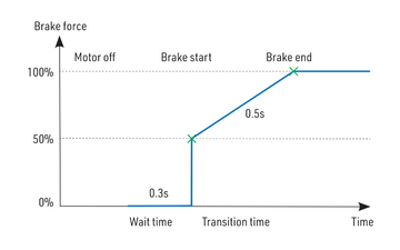
Hard: Transition from 50% to 100% braking force in 0.5s.
Manual: You can enter all brake parameters manually:
- Start power - braking force applied from the moment the brake is applied.
- End power - the braking force applied after the brake ramp time has elapsed (usually the full braking force that brings the motor to a complete stop).
- Transition - the time between the start and end of the brake. During this time, the braking force changes continuously from initial to end force.
- Wait time - the time between disconnecting the motor and applying the brake. During this time, the motor rotates freely without power.
Example: motor brake with the following parameters: Brake start = 50 %, Brake end = 100 %, Ramp = 0.5 s, Waiting time = 0.3 s.
Propeller positioning
The positioning function allows the motor/propeller to be rotated to the exact position required for a safe landing or just convenient for the next flight. With a few external components (a Hall sensor and a small magnet) you can use this function and avoid the risk of damaging the propeller during landing. The magnet must be properly attached to the rotating part (motor or propeller) and the Hall sensor must be positioned in the fuselage so that the magnet is opposite the Hall sensor at the target position of the propeller. After enabling the positioning function via the controller menu (Propeller Position = "Hall Sensor"), also set the PWM positioning so that the motor spins slowly but smoothly. You can also change the duration of the actively held motor position (Position Hold), which is activated when the correct position is found. The Position Hold feature is useful in retractable propulsion because it prevents the propeller from moving spontaneously during retraction.
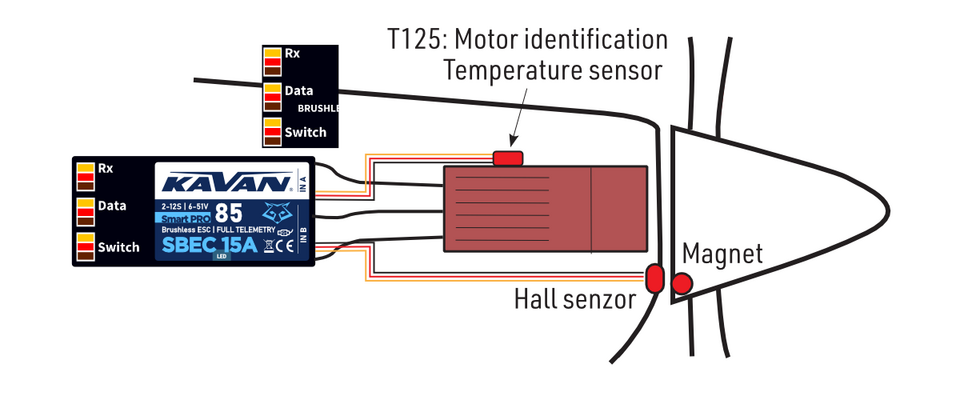
To enable propeller positioning, connect the Hall sensor to the IN-B port on the controller.
Motor identification
Some brands of motors include an integrated temperature sensor compatible with KAVAN SMART PRO controllers. This sensor (T125-ID) can also be used as a stand-alone telemetry sensor with Duplex/Hott/S.Bus2/Fport telemetry support. In addition, it can be connected directly to the "IN-A" input port on the controller (see picture above). From this point on, the KAVAN Smart PRO controller will know the basic motor parameters (minimum acceleration, recommended timing, gear ratio, number of poles...) and also the current motor temperature. Some parameters will be reset automatically (gear ratio, number of poles), and other setting items will be applied once you reset the controller to factory settings. The motor identification sensor is connected to the IN-A port on the controller.
Active freewheeling
"Active freewheeling" or "Active braking" is a feature of the speed controller that reduces heat generated by the ESC during partial load operation. This mode is useful for aerobatic pilots who want not only fast acceleration, but also rapid deceleration. The motor follows throttle stick input in both ways and the pilot feels more "locked-in".
Current limiter
The current limiter is part of the safety features of the controller. It does not stop the motor at overcurrent, but constantly monitors the instantaneous current consumption and adjusts the motor output based on it. When this function is enabled, specify the maximum current allowed and the controller will immediately reduce motor power when the current threshold is exceeded. After the current returns to a safe level, motor power is restored.
Battery feature
The integrated battery protection is based on undervoltage detection and reducing motor power, alternatively shutting down the motor completely. You are free to set the number of cells (or leave automatic detection) and low voltage threshold per cell. Supported battery types are NiXX (1.2V), LiFe (3.6V max) and LiIo/LiPo (4.2V max).
Antispark function
The KAVAN Smart PRO 120/130 and KAVAN Smart PRO 200/220 controllers contain an additional circuit that can be optionally used to prevent sparks when connecting the drive battery. This circuit is connected to the propulsion using a separate cable. Use the "Antispark" cable only for pre-charging the controller capacitors. Never use this cable to power the motor or any external electronic components.
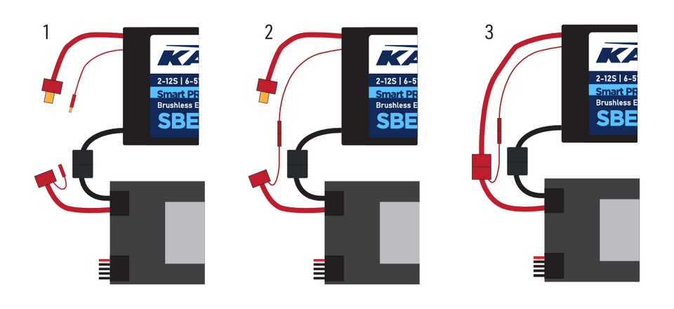
- Connect the negative (-) battery pole.
- Connect the Antispark cable to the positive (+) battery pole.
- Connect the positive (+) battery pole.
Status codes
Status codes are displayed on the screen (JETIBOX/SMART-BOX) if any error event occurs. If any status code is activated, the red LED flashes continuously.
Available status codes:
- Low Voltage (UL): the battery voltage has fallen below the threshold value specified in the Battery Protection menu, and the controller has either reduced the maximum power or shut down the motor completely.
- High voltage (UH): If you use a soft battery or mains power supply, the voltage may rise above the initial level during braking. In this case, an alarm is triggered and all braking functions are disabled.
- High current (IH): the current is higher than the maximum peak current defined in the product specification (e.g. 120 A for KAVAN SMART PRO 80, 200 A for KAVAN SMART PRO 130).
- High temperature (T100, T110, T120): the temperature is above a safe level. The numeric value indicates the maximum temperature detected and the safety protocol that has been activated.
- Commutation (COM) error: a synchronisation error was detected while the motor was running. This usually occurs when the motor stops suddenly or in the case of very fast acceleration on some specific power units. This error may indicate a serious problem in the motor-controller installation.
Mode Heli/governor

The speed controllers include a fast and accurate speed stabilisation function. You can configure the governor mode in many ways to suit your preferences.
Make sure the propeller blades are removed before activating the constant speed mode. In the General Settings menu, select the controller mode to "Heli/governor" and follow the options below:
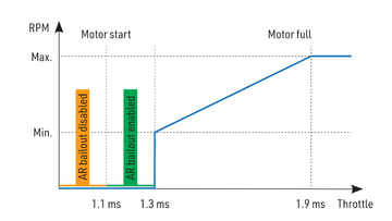
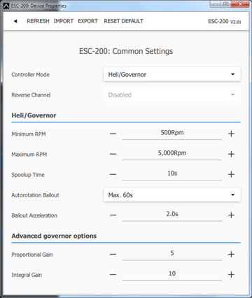
- Set the minimum and maximum RPM of the main rotor according to your preference. As soon as you move the throttle stick beyond the idle position, the motor will slowly rev up until it reaches the target RPM. These are calculated by the throttle channel position, where lowered throttle corresponds to "Minimum RPM" and full throttle corresponds to "Maximum RPM".
- Set the Start Acceleration to make the motor start as smoothly as possible. You can set this time up to 60 s. Start-up Acceleration is used when the motor is revving from zero RPM or when the Autorotation Rapid Exit function is deactivated.
- Configure the autorotation retrieval time and autorotation acceleration. The autorotation retrieval function is used to quickly end the autorotation and prevent the model from crashing. In this case, you move the throttle beyond the idle position, "Autorotation Acceleration" is used to rev up the motor until it reaches the desired RPM. The "Autorotation Retrieval" parameter determines the time after motor shutdown when the autorotation rescue function can be activated. When this time is exceeded, the standard start-up time is used.
- Advanced settings: governor gains - (P)roportional and (I)ntegral. You can adjust these gains to fine-tune the governor's response to rapid load changes during flight manoeuvres. Please make the changes only in small increments and verify the resulting behaviour in a short test flight.
- Increase the gain P to remove small speed fluctuations during straight flight, e.g. hovering. If you hear unexpected motor/gear noise (indicating rapid oscillation), reduce P gain by 20%.
- Increase gain I to maintain precise speed during manoeuvres. If the motor speed fluctuates noticeably, reduce the I-gain by 20%.
- In Governor mode, fixed throttle channel endpoints are always used (standard 1.1–1.9 ms) and active braking is also enabled.
The chart on the right shows RPM response vs. throttle position. In this case, default throttle endpoints have been used (1.1–1.9 ms).
RPM reversing
The RPM reversing function is available for RC systems with bidirectional bus support (EX Bus, P²Bus, SRXL2, S.Bus2, FPort). To control the direction of the motor, you must define an additional bus-transmitted channel on the transmitter. Both Smart PRO controller cables (red and black) must be correctly connected to the receiver.
First, create another channel on the transmitter to control the direction of the motor. This channel should be controlled by a two-position switch.
Futaba/Spektrum:
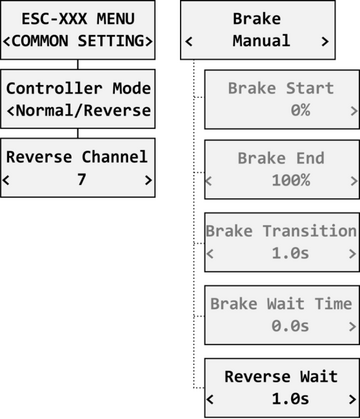
Use one of the AUX channels and remember the channel number. It is not necessary to limit yourself to only the channels available on your receiver, as RC systems usually send more channels on the bus than the physical number of outputs on the receiver.
Example: if you are using a Spektrum NX6 and a six-channel receiver, you can still use channel 7 (AUX2) to control the reversing function over the SRXL2 bus.
JETI:
Create a new model function in the Model - Function Assignment menu and assign a free two-position switch to it. Then, in the Model - Servo Assignment menu, assign this function to one of the receiver channels (1–16). Again, you can also use channels that are not directly available on the receiver outputs (e.g. 13–16) as they will be transmitted over the EX Bus protocol without restriction.
PowerBox:
Create a new function for the model in the Function menu by pressing the "+" button and assign a two-position control switch to it. Select one of the available output channels (1–16). The position of the switch will be transmitted via the P2Bus to the speed controller.
To activate the motor reverse function in the controller, set the "Controller Mode" "Normal/Reverse" and set the reversing channel from the previous step. You can also fine-tune the brake settings and wait time before reversing when using the "Manual" brake type.
Check the function: As soon as you switch the direction switch, the controller activates the brake and after a short pause the motor starts to rotate in the opposite direction.
Galvanic isolation
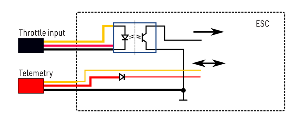
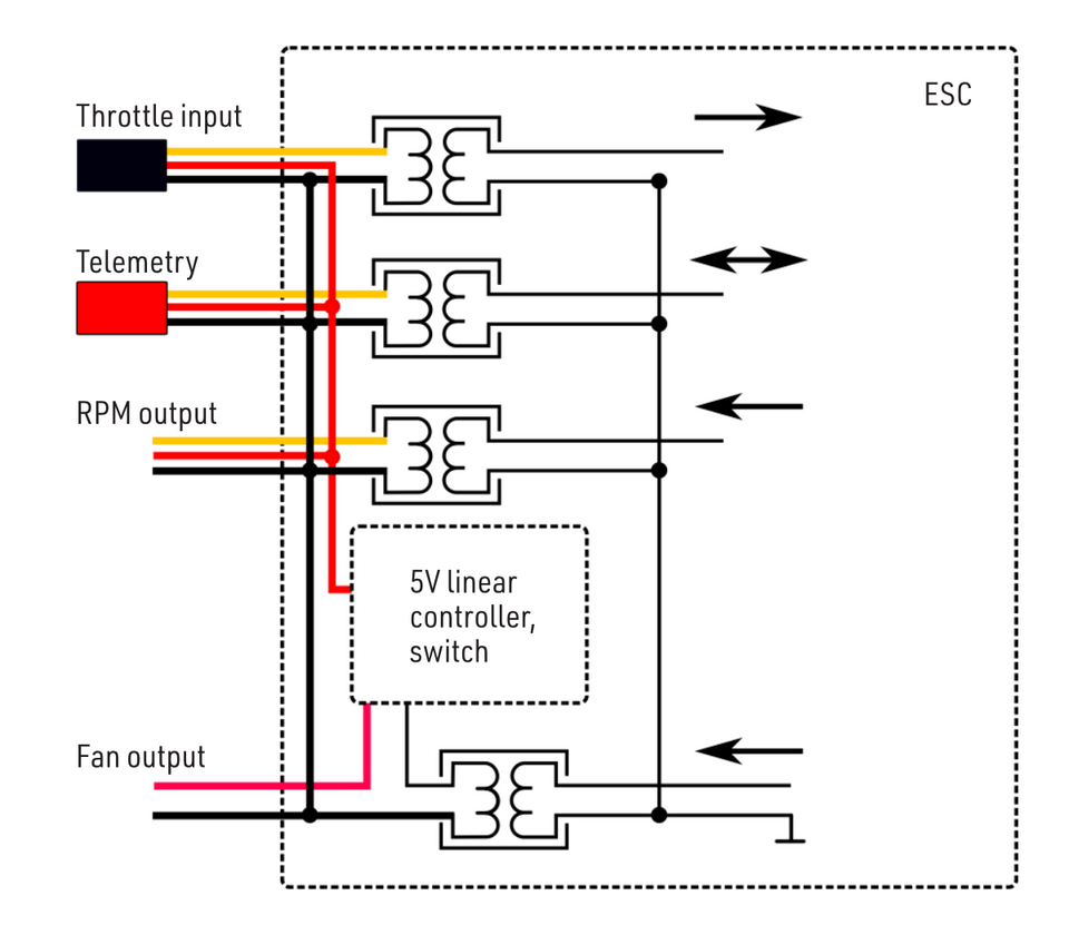
The KAVAN Smart PRO 80 and KAVAN Smart PRO 120/130 controllers have an optically isolated throttle input. Smart PRO-200/220 also include galvanic isolation for all signal wires.
KAVAN Smart PRO 80, 120/130
KAVAN Smart PRO 200/220
Fan control
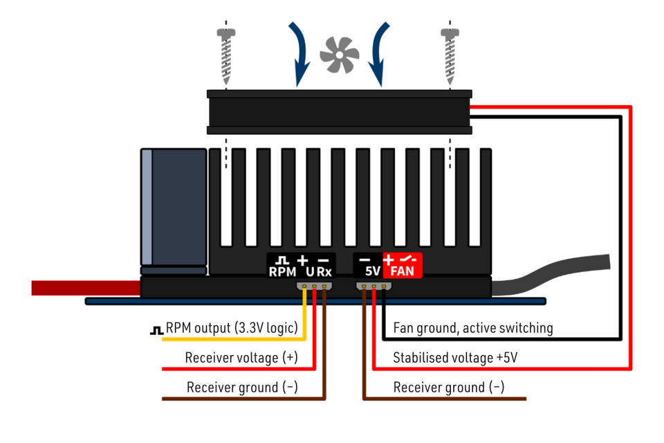
KAVAN Smart PRO 200/220 include a controlled output for an external fan (5 V, up to 300 mA). It is activated when the controller temperature reaches 55 °C.
Use only a suitable fan, which is sold as an accessory to the controller. Attach the fan to the heat sink using the screws provided. Connect the fan to the controller output marked "FAN" as shown on the left. The fan is powered by the receiver battery with the voltage stabilised at 5 V.
Telemetry and settings
Plug the red data cable into the sensor slot of the JETIBOX /SMART-BOX (or corresponding receiver). Power it up with a battery (4.5 - 8.4V). Now you can safely configure the controller using the arrows on the terminal.
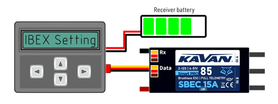
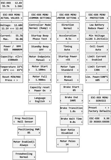
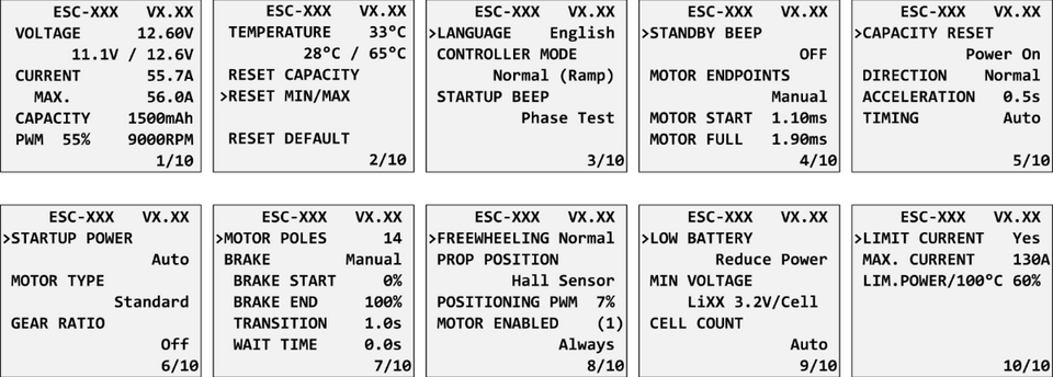
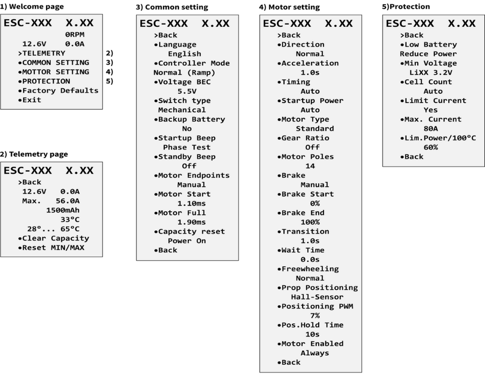
The Smart PRO ESC is compatible with JETIBOX programming. The JETIBOX menu is divided into fivesections:
Actual values
Displays fresh telemetry values along with minimums and maximums.
- Available telemetry: voltage, current, capacitance, RPM, power (percentage), temperature.
- If a Motor-ID chip is connected, the motor identification and temperature will also be displayed.
- Reset Min/Max - press the left and right buttons simultaneously to reset all minimums and maximums.
Common settings
Basic controller settings.
- Controller mode - basic controller mode (normal or fast).
- Startup beep - select the melody to be played after the driver is initialised.
- Standby beep - you can activate short repeated beeps to indicate a live motor.
- Motor endpoints, motor start, motor full - settings related to decoding the throttle input signal.
- Capacity reset - you can choose at which point the capacitance and power consumption are reset:
- Power on - the capacitance is reset after the controller initialisation. However, the capacitance from the previous run will be displayed initially until you start the motor.
- Voltage change - the capacitance is cleared when a battery with a similar (or higher) voltage, compared to the maximum battery voltage from the previous run, is connected. This means that every time you connect a fully charged battery of the same composition and cell count, the capacitance will be cleared.
- Manual - capacitance and energy are never reset and you must reset them manually.
- Language - you can select the language of the JETIBOX screen.
Motor settings
Settings related to motor parameters.
- Direction, acceleration, timing, starting power, motor type, gear ratio, number of motor poles - see chapter Motor settings.
- Brake related settings - see chapter Brake configuration.
- Prop position, positioning PWM, position hold time - see chapter Propeller positioning.
- Motor enabled (0/1) - motor start can be enabled or disabled based on the logic state of the specific input "IN B.2" (connector pin from left to right: 1 = Hall sensor input, 2 = motor enable input, 3 = 3.3 V, 4 = GND). If you select "Vst.pin Log0/1", you must always turn the throttle down before starting the motor. On the other hand, if you select "Autostart Log0/1", the motor will start as soon as the logic value of the input pin allows it and the throttle position is above idle.
- Freewheeling - allows you to enable synchronous switching (active brake) or leave the standard controller mode.
Protection
Setting the controller and battery protection.
- Low battery - behaviour when the battery is low. Either, the motor power will slowly decrease or it will shut down immediately. The minimum safe voltage is calculated from the number of cells and the minimum cell voltage.
- Limit current - enable this function to prevent high current spikes and system overload.
- Limit power at 100 °C - you can adjust the maximum allowed PWM of the controller after its temperature exceeds 100 °C. The model must be operational, but the temperature must no longer increase.
Service
In this menu, you can view the version of the device and reset it to the factory default configuration.
EX and P²Bus and FPort telemetry available:
- Battery voltage (V)
- Motor current (A)
- Capacity (mAh)
- Speed (RPM)
- PWM (%)
- Power (W)
- Running time (s)
- Energy (Wmin) - useful function for competitions where total energy is limited - F5B, F5D.
- Temperature (°C)
- External temperature (°C) - if a motor ID chip is connected, the controller sends the motor temperature as its telemetry.
Motor status:
- 0 = Initial state
- 1 = Motor running
- 2 = Braking
- 3 = Positioning started
- 4 = Position found
- 5 = Position error (propeller moved)
The KAVAN Smart PRO controller is recognized as an "Air-ESC" sensor by default.
Futaba and Multiplex connection
Futaba and Multiplex systems do not offer wireless configuration of connected devices. Telemetry transmission is possible using the following fixed sensor slots:
| Futaba S.Bus2 slot | Note | Slot Multiplex MSB | |
|---|---|---|---|
| RPM | 2 | Choose the RPM sensor on slot 2. | 6 |
| Current | 3 | Choose the SBS01C current sensor on
slot 3. |
3 |
| Voltage | 4 | 2 | |
| Capacity | 5 | 4 | |
| Temperature | 6 | Choose the Temp125 sensor on slot 6. | 5 |
| PWM (0–100%) | 7 | Choose the Temp125 sensor on slot 7. | - |
| Note | Manual detection in menu Linkage - Sensor. | Automatically detected by the transmitter. | |
PowerBox Telemetry
From version 1.09, the KAVAN Smart PRO controller can recognise the PowerBox P²Bus telemetry protocol. Connect the telemetry cable (red connector) to the P²Bus port on the receiver. The transmitter will locate the connected sensors when the receiver is switched on. The controller telemetry should then be available within 2.5 seconds. You can now assign telemetry values to any widgets and alarms on the transmitter's screen. The available telemetry is similar to the Duplex EX telemetry (see above). Configuring the controller via the PowerBox transmitter is not available at this time.
Spektrum Integration
From version 1.06, Spektrum telemetry support is integrated with a special firmware version. This alternative firmware offers SRXL2 telemetry and TextGen settings. The KAVAN Smart PRO controller is represented in the transmitter by two telemetry devices:
- "ESC" displays battery voltage, current, BEC voltage, controller temperature, RPM and output power.
- "Flight Pack Capacity", which shows the consumed battery capacity.
Connect the throttle cable (black connector) to the THR receiver port (1). For proper telemetry/setup operation, also connect the telemetry cable (red connector) to the Prog/SRXL2 receiver port. The controller provides only numeric telemetry by default. The text menu (TextGen) is only available after a special start-up procedure:
- We assume that the throttle and telemetry cables are correctly connected and the transmitter is switched on. Now set the remote control to the "Full throttle" position.
- Switch on the controller either by connecting the propulsion or by switching on the external switch.
- The motor will start, indicating full-throttle pulse detection. After 3 seconds, another beep will signal entry into the programming menu.
- You can now fully turn the throttle down. From the transmitter's main screen, scroll to the right and locate the TextGen menu. If the text menu is activated, the motor will never start revving. To get the motor running normally again, exit the TextGen menu by selecting "Exit" on the main page.
- The menu navigation is provided by the transmitter sticks - the elevator stick moves the cursor up/down and the aileron stick changes the selected value.
- Configuration changes are saved immediately after any value is modified.
- Use the latest firmware version in your transmitter and receiver. For Spektrum NX, at least version 3.06 has to be installed. Recommended receivers: AR8360T, AR8020T, AR6610T, AR631T, AR637T…
- The Smart PRO version 2.01 and later is compatible with Spektrum single-cable operation (Smart Throttle). To enable this function, just plug the red telemetry cable into receiver channel No.1 and keep the other (black) cable unplugged. You will be able to control throttle as well as receive telemetry. This approach is compatible with AR10400T receiver family as well.
- If you use an ESC with a galvanic isolation (Smart PRO 200/220), always turn on the ESC before the receiver. Otherwise the telemetry functions may not work.
Safety information
- Always use the KAVAN Smart PRO controller in a dry environment and within the limits of the equipment specified in this manual. Never expose the device to excessive heat or cold outside the operating range.
- Ensure sufficient airflow to prevent the controller from overheating.
- Never exceed the maximum allowed operating voltage of the controller or the motor.
- Do not increase the cable length between the controller and the motor. If you need to extend the wires between the ESC and the battery to more than 30 cm (total), solder several high-capacity Low-ESR capacitors (220–470 µF) in parallel to the power wires as close to the ESC as possible. For each centimetre over the specified length of the cables, add 1 µF of capacitance per 1 cm of length for each ampere of current passing through. At 10 cm over the limit for 100A current, connect 1000 µF capacitors.
- Always use high-quality connectors in good condition. If there are any visible signs of wear, replace them.
- Always remove the propeller before making any changes to the drive setup.
- Never disconnect the controller from the battery while the motor is revving.
- Do not remove the packaging and heat sink from the unit or attempt to make any changes or adjustments. Doing so may result in irreversible damage and denial of any warranty claims.
- Always check the polarity of the connections. Never reverse the polarity - this could lead to irreversible damage.
Firmware updates
Firmware updates for KAVAN Smart PRO controllers are uploaded from a computer via USB. The required software and files are available at www.mavsense.com.
Install the MAV Manager software and drivers for the USB interface on the computer. Check the system requirements.
- Make sure the flight battery is disconnected and the KAVAN Smart PRO controller is unpowered.
- Connect the USB interface to your computer, start the MAV Manager - Updater and select the correct COM port.
- Connect the controller as shown below - use the red (telemetry) port. The controller will be automatically detected.
- Select the correct *.bin file and press the Update button.

- The Smart PRO-80 and Smart PRO-120/130 do not require connecting the flight pack prior to updating. These controllers are powered directly from the USB interface.
- On the other hand, the Smart PRO-200/220 requires connecting at least a 3S LiPo main battery since the power circuit is completely galvanically isolated from the signal interfaces. Always start the MAV Manager first and connect the controller through the USB interface. The external battery should be connected afterwards to prevent the controller going to sleep mode.
PC Configuration
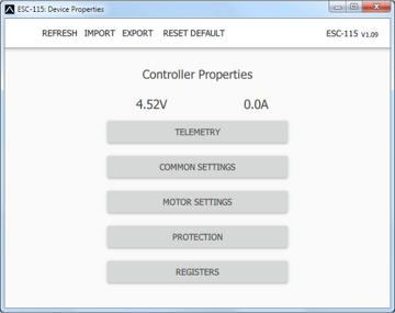
It is possible to use the MAV Manager software (version 1.4.0 and newer) to conveniently configure all controller parameters, display real-time telemetry or backup the configuration. The program menu contains four buttons in the upper toolbar:
- Refresh - forces a reload of the configuration from the controller.
- Import - imports the settings from a file. If you have several controllers and want to have all of them identically configured, simply import the same settings file into each controller.
- Export - exports the settings from the controller to a file. You can easily create a backup configuration that will be stored on your computer. After creating a backup, you can easily experiment with the controller settings and later revert to the original configuration by pressing the "Import" button and selecting the original saved file.
- Reset default - resets the controller to the factory default settings and reloads the entire configuration.
Connect the controller to a computer using the USB interface. It is automatically detected by the MAV Manager.
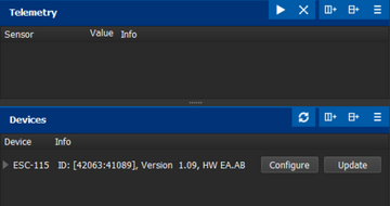
The controller properties are available by pressing the "Configure" button.
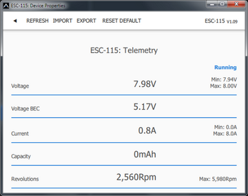
Real-time telemetry with min/max values. MAV Manager is also capable of creating a log file from real-time telemetry data that can be viewed, analyzed, imported and exported.
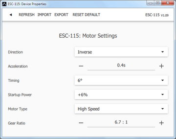
Motor Settings. Whenever a configuration change is made, the new value is immediately transferred to the controller and stored in memory. No additional confirmation is required. For safety reasons, some parameters are only applied after the motor has stopped.
Manufacturer
All KAVAN Smart PRO electronic speed controllers are made in Czechia by MAV Sense s.r.o.
E-mail: info@mavsense.com | Web: www.mavsense.com
Recycling and waste disposal note (European Union)

Electrical equipment marked with the crossed-out waste bin symbol must not be discarded in the domestic waste; it should be disposed of via the appropriate specialised disposal system. In the countries of the EU (European Union) electrical devices must not be discarded via the normal domestic waste system (WEEE - Waste of Electrical and Electronic Equipment, Directive 2012/19/EU). You can take your unwanted equipment to your nearest public collection point or recycling centre, where it will be disposed of in the proper manner at no charge to you. By disposing of your old equipment in a responsible manner you make an important contribution to the safeguarding of the environment.
EU declaration of conformity (European Union)

Hereby, KAVAN Europe s.r.o. declares that these KAVAN Smart PRO line brushless electronic speed controllers are in compliance with the essential requirements as laid down in the EU directive(s) concerning electromagnetic compatibility. The full text of the EU Declaration of Conformity is available at www.kavanrc.com/doc.
Guarantee
The KAVAN Europe s.r.o. products are covered by a guarantee that fulfils the currently valid legal requirements in your country. If you wish to make a claim under guarantee, please contact the retailer from whom you first purchased the equipment. The guarantee does not cover faults which were caused in the following ways: crashes, improper use, incorrect connection, reversed polarity, maintenance work carried out late, incorrectly or not at all, or by unauthorised personnel, use of other than genuine KAVAN Europe s.r.o. accessories, modifications or repairs which were not carried out by KAVAN Europe s.r.o. or an authorised KAVAN Europe s.r.o., accidental or deliberate damage, defects caused by normal wear and tear, operation outside the Specification, or in conjunction with equipment made by other manufacturers. Please be sure to read the appropriate information sheets in the product documentation.