In Bearbeitung – die Übersetzungen werden erstellt. Bis dahin steht hier die englische Anleitung zur Verfügung.
Freewing Ares 3D 1156 mm – Instruction manual

Freewing Ares 3D 90 mm PNP 8S+Gyro Red

Freewing Ares 3D 90 mm PNP 8S+Gyro yellow
Introduction
The Ares 3D is a factory-built EPO radio-controlled aircraft supplied in PNP configuration. The airframe requires final assembly, a compatible radio system and the flight battery specified below. Complete the mechanical, radio and balance checks before flying.
Safety notes and warnings
This model is not a toy. Incorrect assembly or operation can cause serious injury. It is intended for experienced RC pilots; inexperienced users need competent assistance. For ages 14 and above; anyone under 14 may operate it only under an adult’s instruction and supervision. Read and retain the complete instructions, including those supplied with the radio, battery, charger, ESC and any gyro.
- Keep hands, hair, clothing and loose objects away from the EDF intakes, rotors and exhausts. A fan can draw in objects and eject debris.
- Keep the flight battery disconnected during assembly, transport and maintenance. Connect it only when the model is secure and the propulsion area is clear. Treat the motor as live whenever power is connected.
- Fly in an unobstructed area clear of people, animals, roads, power lines and buildings. Maintain a safe distance and follow the applicable model-flying rules at your site.
- Do not fly in rain, poor visibility or unsuitable wind, or with a damaged airframe, weak transmitter battery or unreliable radio link.
- Use only a compatible LiPo balance charger with the correct cell count and charging settings. Supervise charging on a non-flammable surface. Do not use damaged, swollen or overheated batteries.
- Keep water, solvents and excessive heat away from the model and electronics. Do not leave the foam airframe or batteries in a hot vehicle or direct heat.
Keep a 2 m clear area around stored flight batteries, free of combustible and explosive materials. Take damaged or exhausted batteries to a suitable battery collection facility. Collect waste at the flying site; do not discard or burn it. Never try to catch the aircraft in flight or during landing—wait until it has stopped and the propulsion is safe.
Features
- Painted EPO airframe with factory-installed propulsion and servos.
- 1× Ø90 mm EDF, 12-blade rotor.
- Electric retractable landing gear.
- Working flaps.
- Installed LED lighting.
- Installed flight-stabilisation system; complete its model-specific checks before flight.
Technical specifications
| Parameter | Value |
|---|---|
| Wingspan | 1156 mm |
| Length | 1400 mm |
| Weight | 2721 g (excluding drive battery) |
| Airframe | EPO |
| Propulsion | 1× Ø90 mm EDF, 12-blade rotor |
| Brushless motor | 4075-1350 KV |
| ESC | 120 A |
| Installed servos | 11 |
| Landing gear | Electric retracts |
| Flight battery, not included | 8S 5000–6000 mAh LiPo |
| Radio system, not included | At least 8 channels for the basic arrangement; additional functions may require more channels |
| Battery compartment | 230×60×70 mm |
| Battery discharge rating | At least 50C |
Package contents
Painted fuselage, wing and tail/control-surface assemblies; installed brushless propulsion, ESC and servos; linkages, specified joiners and assembly hardware; the landing gear and scale fittings supplied for this version. The flight-stabilisation equipment is included in this configuration. The transmitter, receiver, flight battery and charger are not included. Check every part against the supplied packing list before beginning; contact the supplier if anything is missing or damaged.
Required equipment
- A compatible transmitter and receiver with at least 8 channels for the basic functions. Allow extra channels where independent surfaces, thrust vectoring, gyro controls, wing sweep or reverse are specified.
- A suitable flight battery: 8S 5000–6000 mAh LiPo. Check its dimensions, mass, connector and cell count against the supplied power system and CG before use.
- A LiPo balance charger suitable for the selected battery and a charged transmitter battery.
- Suitable screwdrivers and hex drivers, pliers, a ruler/control-throw gauge, a balance stand and a padded model support.
- EPO-compatible adhesive for the joints specified in the assembly instructions. Test compatibility first; allow the adhesive to cure fully. Use threadlocker only where specified for metal-to-metal fasteners and keep it away from plastic and foam.
Main section
Preparation
Leave the flight battery disconnected. Remove propellers from propeller-driven models. On an EDF model, isolate the motor connection for radio/servo work where accessible, insulating loose connectors individually; disconnect the flight battery before changing any wiring. Restore the original motor connections only for controlled propulsion checks.
- Inspect the foam, hinges, joiners, horns, motor mounts and installed wiring for transport damage. Identify left/right parts and the correct fasteners.
- Trial fit the assemblies before applying adhesive. Do not force a joint or use glue to compensate for an incorrectly fitted part.
- Keep servo and lighting plugs accessible while joining assemblies. Route cables through their channels and protect them from screw tips, moving linkages and landing-gear mechanisms.
- Use only the screws specified for each location. Tighten securely without crushing foam or stripping plastic threads.
Assembly
Tail surfaces
Tail surfaces — 1
Tail surfaces — 2
Tail surfaces — 3
Tail surfaces — 4
Tail surfaces — 5
Tail surfaces — 6
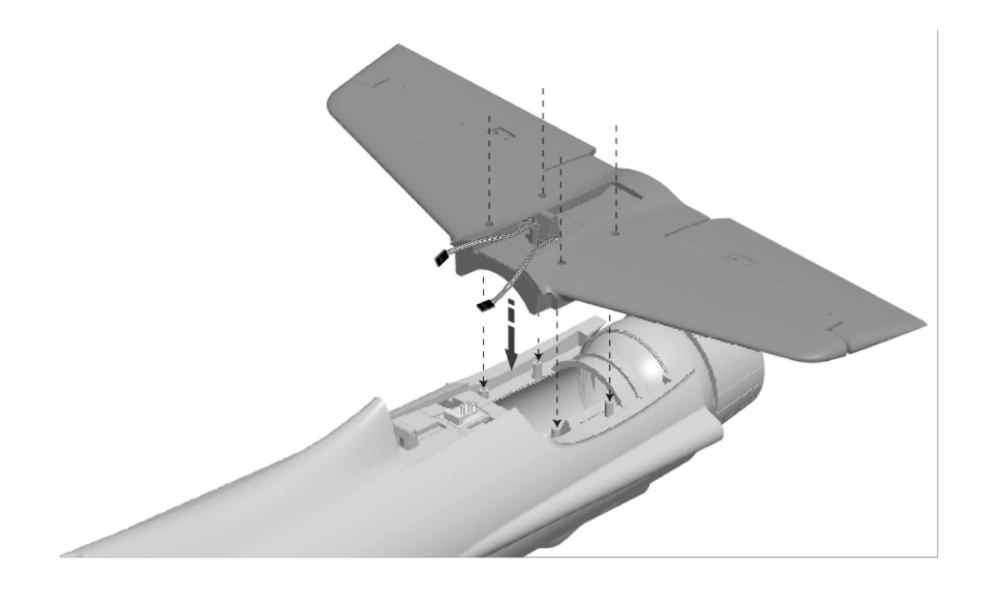
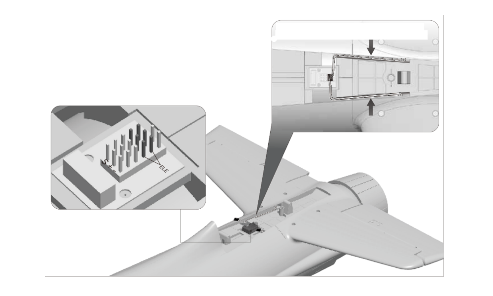
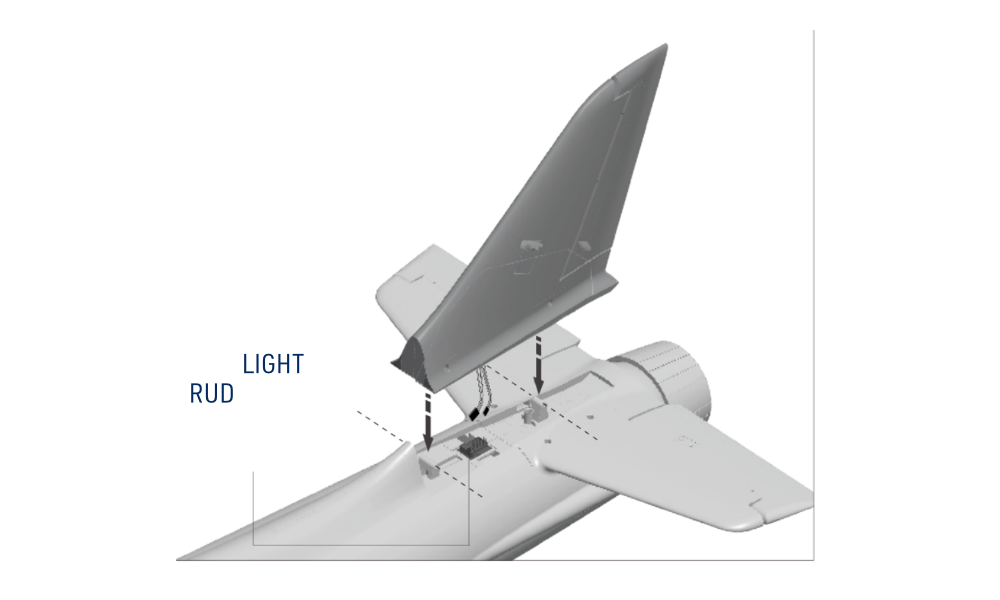
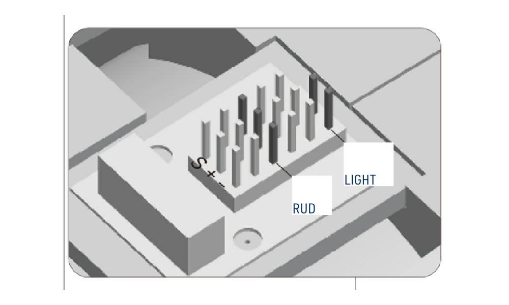
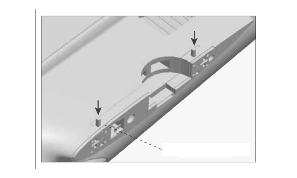
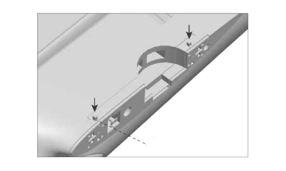
Seat and screw the horizontal tail to the fuselage. Plug the elevator lead into the tail board and arrange it in the cable tray before fitting the fin. Connect the rudder and LED leads to their labelled sockets, seat the fin and secure it with four KM3×7 screws.
QUICK II wings
QUICK II wings — 1
QUICK II wings — 2
QUICK II wings — 3
QUICK II wings — 4
QUICK II wings — 5
QUICK II wings — 6
QUICK II wings — 7
QUICK II wings — 8
QUICK II wings — 9
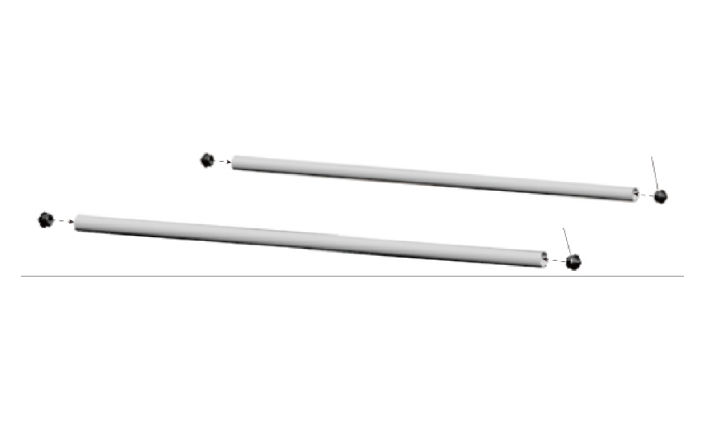
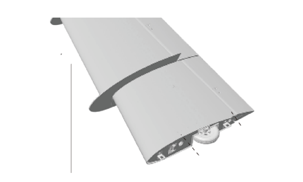
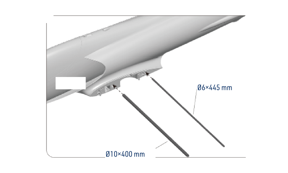
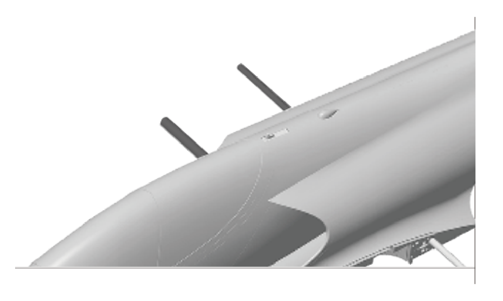
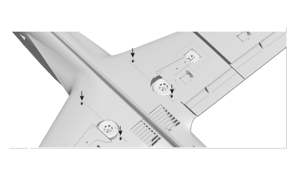
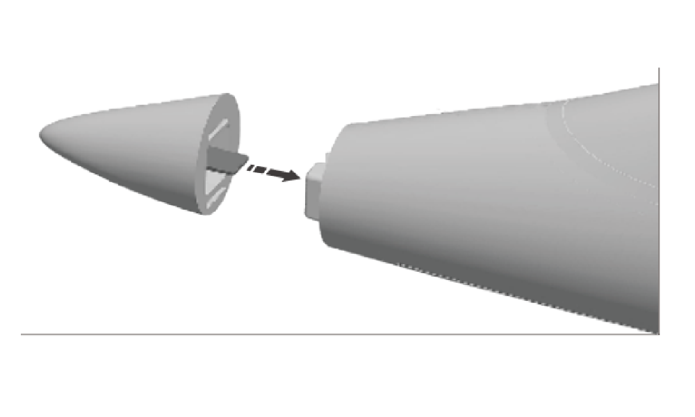
Glue the matching conical plastic tips onto the Ø10×400 mm and Ø6×445 mm carbon joiners. Let the adhesive cure, then install the joiners in the fuselage. Unlock the wing latches by pressing and releasing the buttons until they rise. Slide both wings into place with their connections seated. Press all four buttons until they remain down and gently pull-check both wings. Fit the magnetic nose.
Receiver connections
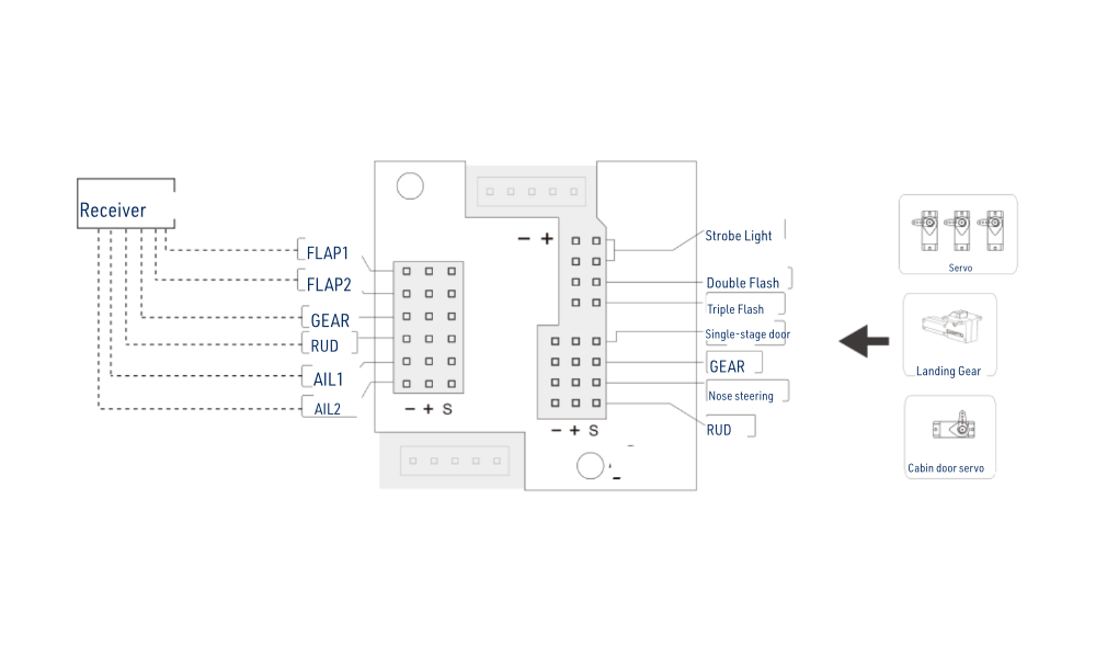
Main control board
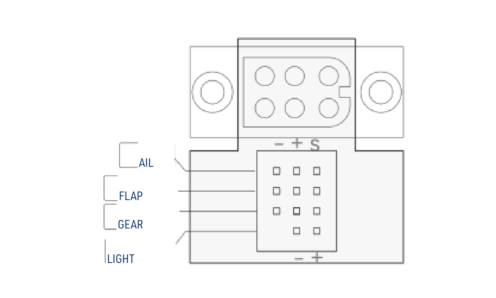
Wing connection board
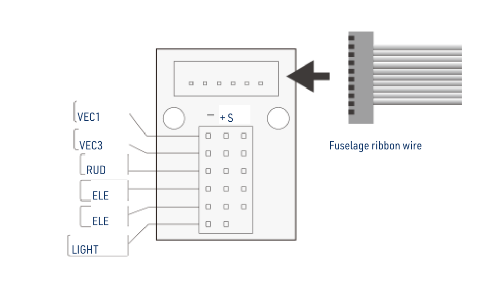
Tail connection board
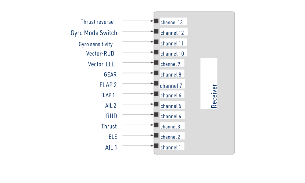
Full receiver-channel assignment
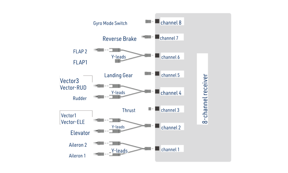
Eight-channel receiver assignment
Choose the receiver arrangement before programming. With separate outputs, assign CH1 aileron 1, CH2 elevator, CH3 throttle, CH4 rudder, CH5 aileron 2, CH6 flap 1, CH7 flap 2, CH8 gear, CH9 vector pitch, CH10 vector yaw, CH11 gyro gain, CH12 gyro mode and CH13 reverse. The eight-channel arrangement uses Y-leads for paired ailerons, elevator/vector pitch, rudder/vector yaw and flaps; CH5 operates gear, CH7 reverse and CH8 gyro mode. In that eight-channel arrangement the remote gyro-gain lead remains disconnected. Follow the matching wiring drawing and verify every function.
Receiver installation and radio setup
- Select the correct aircraft memory and label it with the model/version. Keep throttle at its minimum position and enable throttle cut. Bind the receiver following the binding procedure for the radio system with propulsion disabled.
- Connect each labelled control lead to its corresponding receiver or control-board function. Follow the board’s signal, positive and negative markings; do not assume every transmitter uses the same channel numbering. Retain the supplied BEC/UBEC wiring.
- Secure the receiver and any extensions. Follow the receiver’s antenna-placement requirements and keep antennas clear of power wiring, carbon reinforcement and moving parts.
- Centre the servos and set the mechanical neutrals described below before adjusting travel or mixes. Ensure clevises are fully engaged and fit their retaining sleeves; press ball links completely onto their balls.
- Program the required functions, control rates and failsafe. Set failsafe to stop the motor and verify its actual operation with propulsion disabled. Recheck after changing the receiver, transmitter memory or control-board configuration.
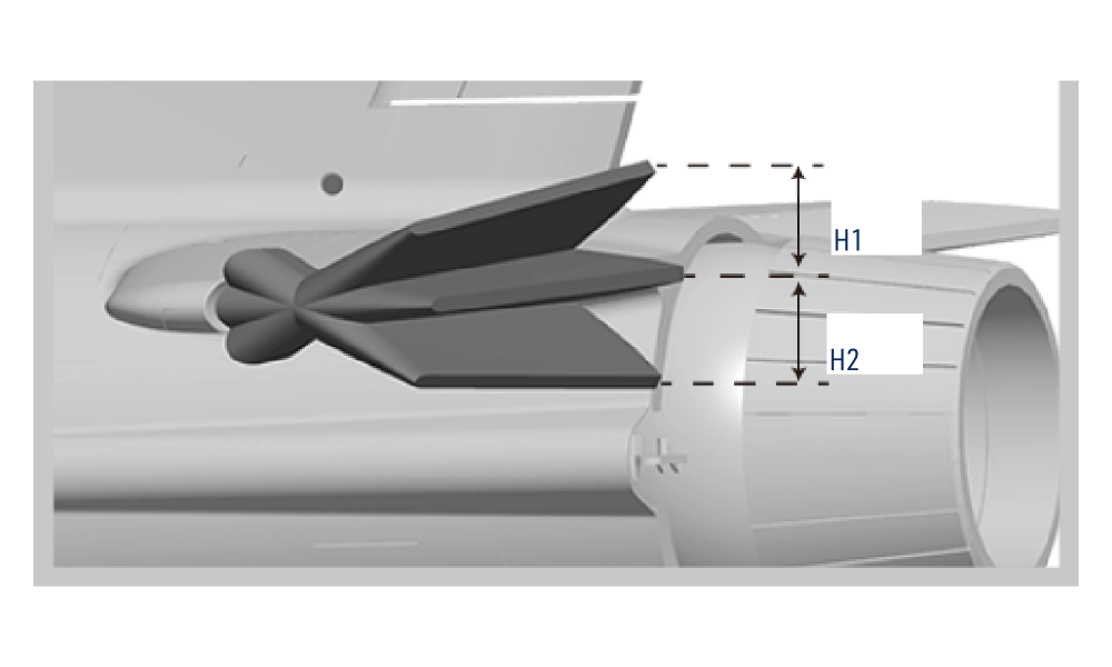
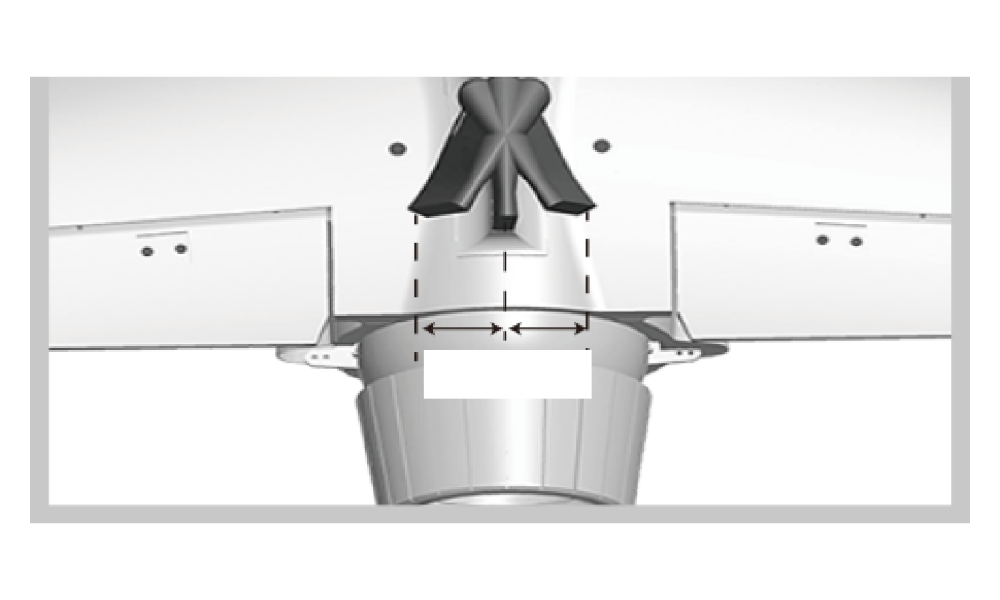
Mix 2 mm down elevator when the flaps are lowered. Centre the vector nozzle in pitch with the centre of raised point A approximately 3 mm from line B in the direction shown. For yaw, align line C with the centre of point A and keep C centred and parallel in the plastic groove. Suggested expo is −30 % Futaba / +30 % Spektrum on all three axes. Use basic flight mode for inverted flight; the large 3D elevator/rudder commands can stall a wingtip.
3D transmitter programming
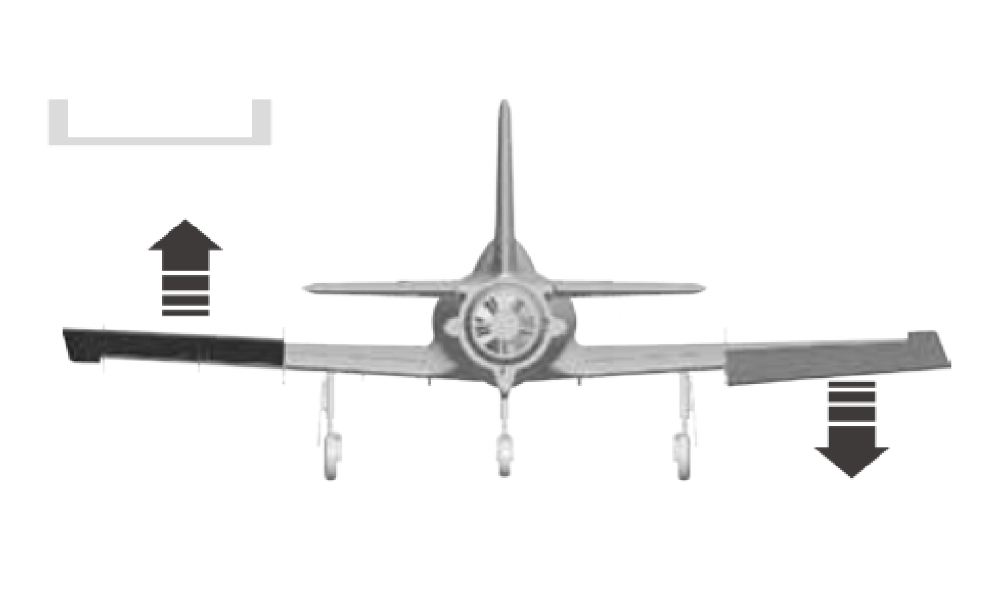
Basic flight mode: Aileron — stick left
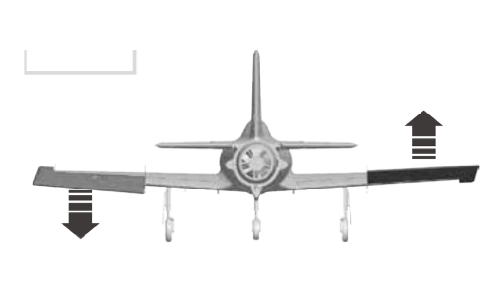
Basic flight mode: Aileron — stick right
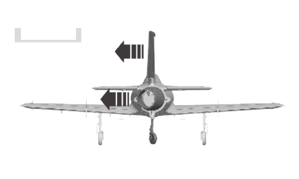
Basic flight mode: Rudder — stick left
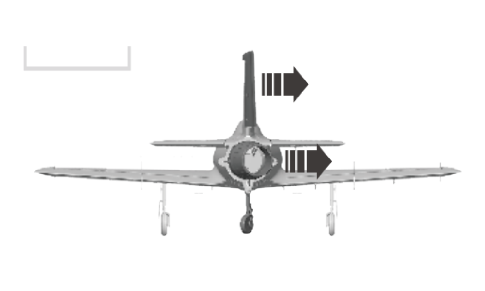
Basic flight mode: Rudder — stick right
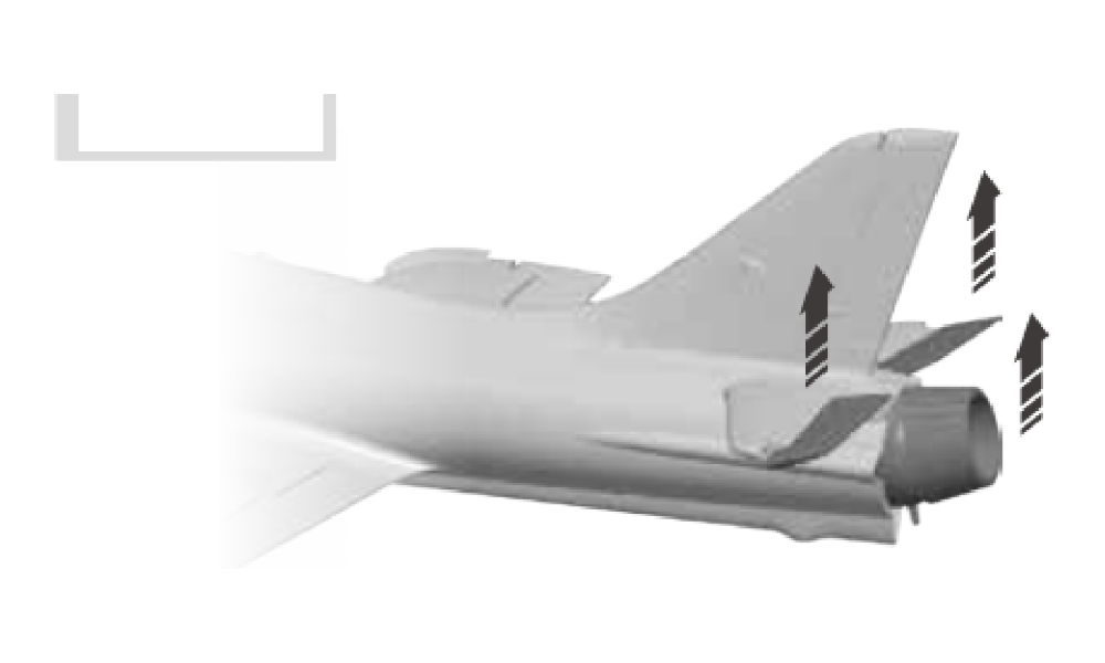
Basic flight mode: Elevator — pitch up
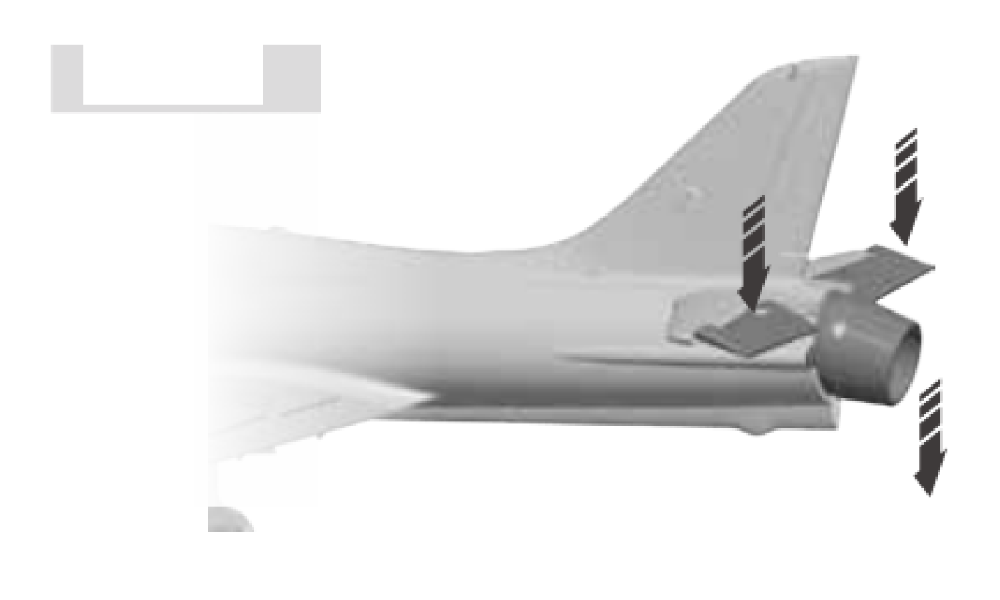
Basic flight mode: Elevator — pitch down
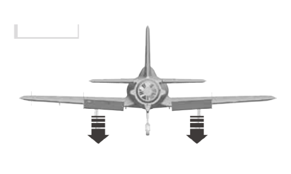
Basic flight mode: Flap — flaps down
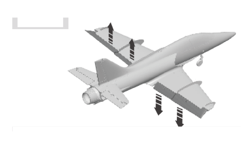
3D flight mode: Aileron — stick left
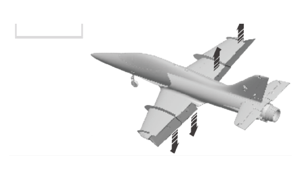
3D flight mode: Aileron — stick right
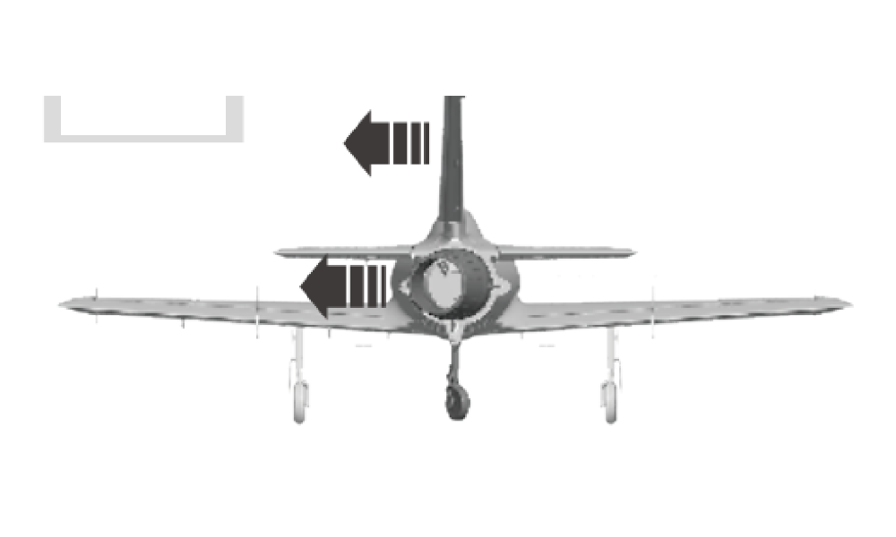
3D flight mode: Rudder — stick left
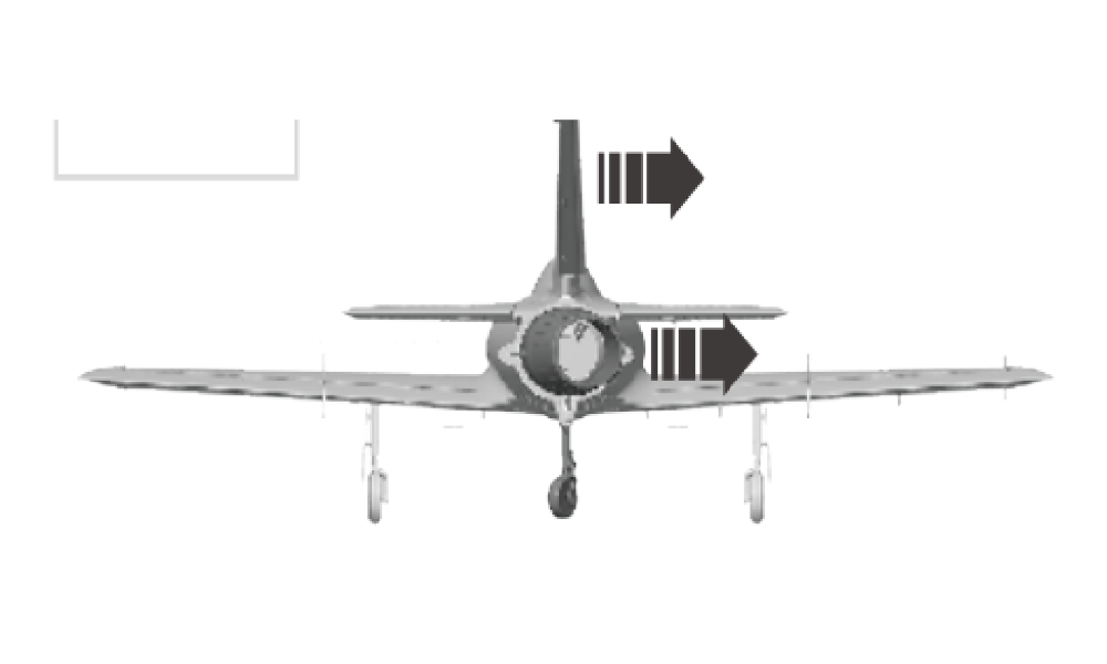
3D flight mode: Rudder — stick right
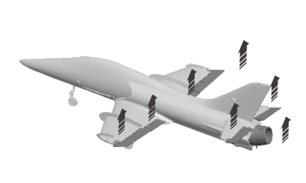
3D flight mode: Elevator — pitch up
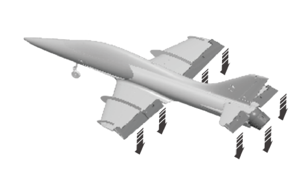
3D flight mode: Elevator — pitch down
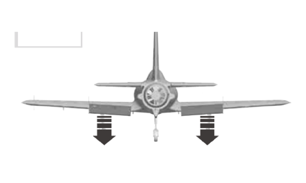
3D flight mode: Flap — flaps down

Futaba model type: 2 AIL + 2 FLP

Aileron-to-camber-flap mix: curve

Aileron-to-camber-flap mix: travel

3D transmitter programming — 18

3D transmitter programming — 19

Elevator-to-camber mix: curve

Elevator-to-camber mix: surface contributions

Elevator-to-camber mix: activation

3D transmitter programming — 23

3D transmitter programming — 24

Elevator-to-vector pitch mix: curve

Elevator-to-vector pitch mix: configuration

3D transmitter programming — 27

3D transmitter programming — 28

Rudder-to-vector yaw mix: curve

Rudder-to-vector yaw mix: configuration

3D transmitter programming — 31

3D transmitter programming — 32

3D transmitter programming — 33
For a Futaba T16IZ SUPER, select an airplane model with a 2 AIL + 2 FLP wing and normal tail. The settings below apply to this transmitter setup; do not assume the percentages transfer unchanged to another radio.
| Mix | Reference setting |
|---|---|
| Aileron → camber flap | Enable on switch SD; rates A/B +100; flap/flap 2 travel +110 on both sides; zero offset/expo; link off |
| Elevator → camber | Enable on SD; rates A/B +110; aileron/aileron 2/flap/flap 2 contributions −100 in both directions; zero offset/expo |
| Elevator → vector pitch | Master Elevator, slave Auxiliary 5; rates A/B +130; trim on; links off; linear servo speed and zero delay |
| Rudder → vector yaw | Master Rudder, slave Auxiliary 4; rates A/B −130; trim on; links off; linear servo speed and zero delay |
Check all resulting surface and nozzle directions against the basic/3D diagrams. Enable 3D mixes only after the basic mode has been verified and test-flown.
Follow the illustrated connections and settings.
Two-gyro supplement

Configure Gyro A with the app profile Ares-90mm (Basic) and Gyro B with Ares-90mm (Vector). Vector 1 controls pitch and Vector 3 yaw. Keep the steering/board connections exactly as shown and mark the specified wire ends to avoid confusion. Gear and door connections go directly to the appropriate receiver/board outputs. Omit the mode-control lead only if no in-flight mode change is required; the default mode is NORMAL. Do not confuse this optional mode lead with a required signal or power connection.
Follow the illustrated connections and settings.
Stabilisation checks
Keep the model stationary during gyro initialisation. Use the factory profile for this exact aircraft and check the normal stabilisation response with the motors stopped. Move the model by hand in roll, pitch and yaw: the commanded corrective response must oppose the disturbance. A system that reinforces the movement will make the model uncontrollable. Check both normal pilot inputs and gyro corrections, including any vector nozzles. Do not fly until both are correct.
Thrust reverse
Where the supplied ESC has a reverse-control lead, connect it to a suitable switched receiver channel following that ESC’s instructions. Check the normal/reverse switch direction with the model secured and the propulsion area clear. Start with normal thrust selected and throttle at minimum. Reduce throttle to zero before changing direction. Use reverse only on the ground after landing; do not select it in flight.
Flight battery and power-system check
Use 8S 5000–6000 mAh LiPo. Follow the discharge requirement in the specification table where provided, and the requirements of the supplied power system. Fit the battery without forcing the canopy or crushing wires. Use the retaining straps and a non-slip support, and adjust its position for the specified CG. Leave it disconnected while balancing and completing the installation.
- Check polarity and connector security with the battery disconnected. Make sure cooling inlets and outlets are clear.
- Switch on the transmitter with the correct model memory, throttle at minimum and throttle cut enabled. Secure the aircraft and keep everyone clear before connecting the flight battery.
- Wait for the ESC and any gyro to initialise. Stop if there is an unexpected tone, error indication, servo movement or motor start.
- Calibrate the throttle range only by the instructions for the installed ESC. Repeat when required after changing the radio system; do not use an unverified generic high-throttle startup procedure.
- With propulsion correctly assembled, check rotation and response in a clear area. Stop immediately if there is vibration, rubbing or an abnormal noise. Disconnect the battery before investigating.
Linkage reference
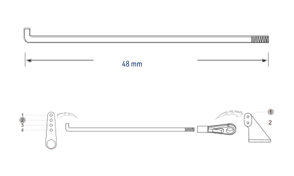
Aileron linkage
Flap linkage
Elevator linkage
Rudder linkage
Elevator linkage
Rudder linkage
Nose-wheel steering linkage
Nose-wheel steering linkage
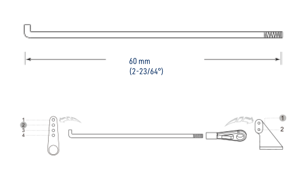
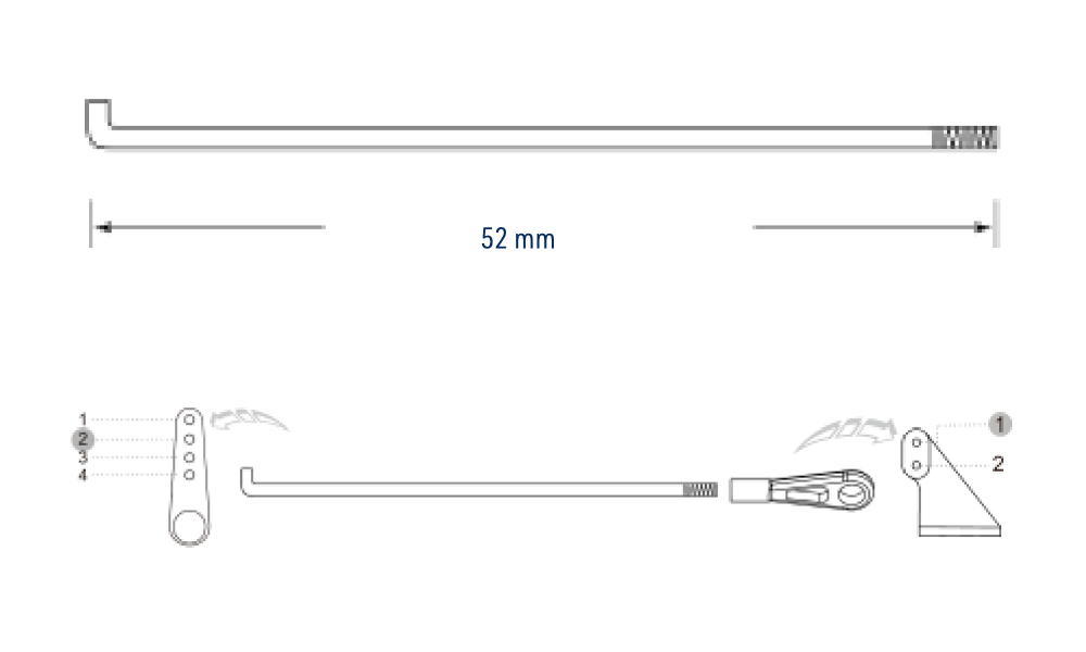
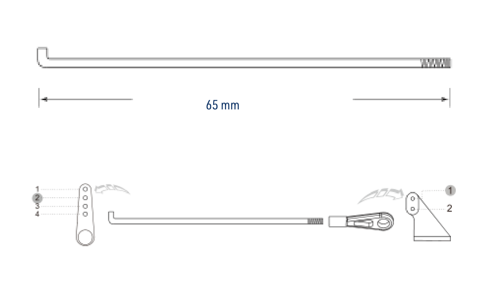
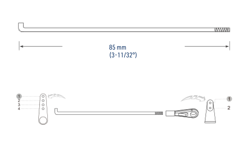
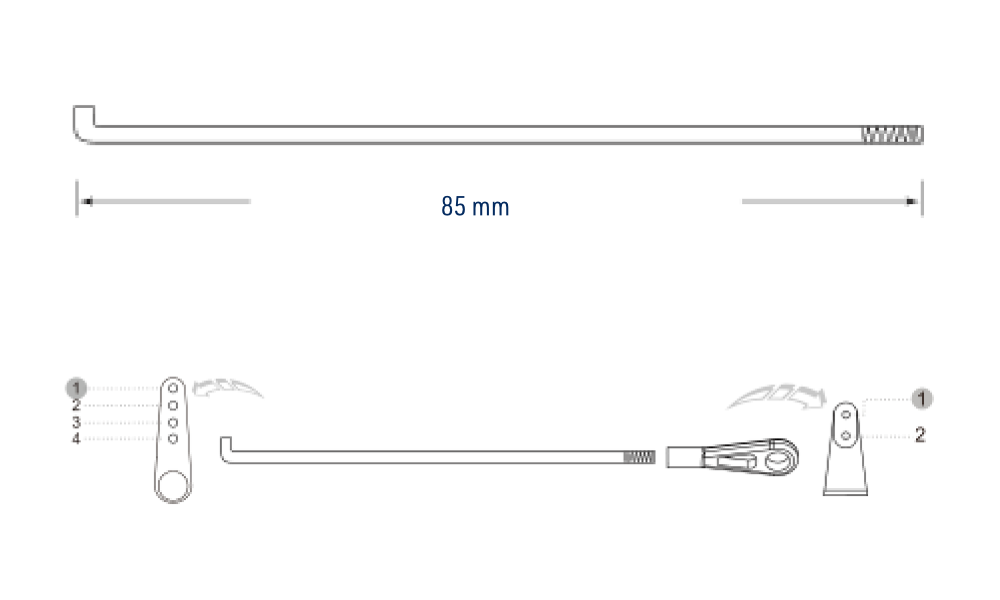
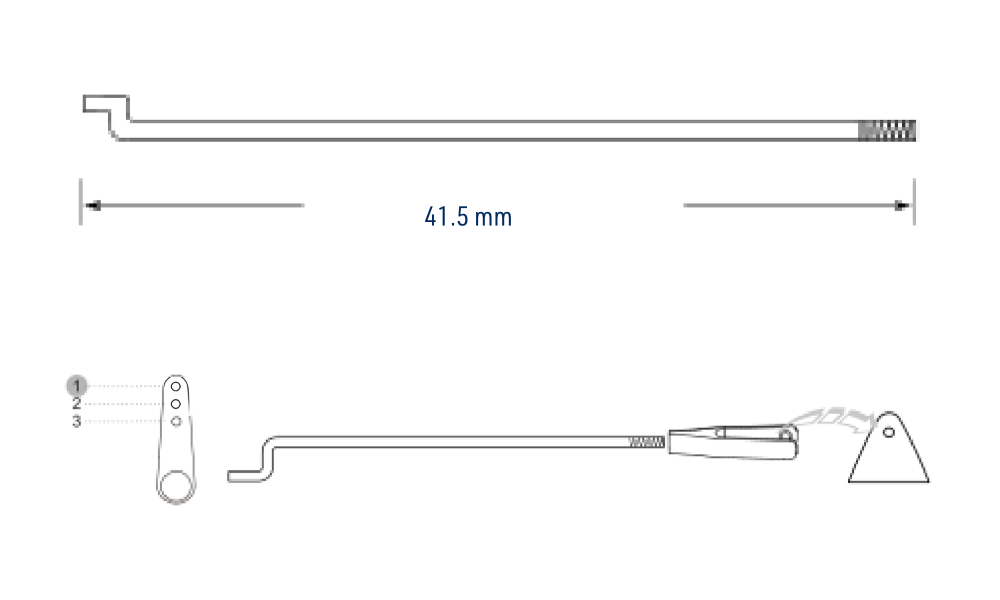
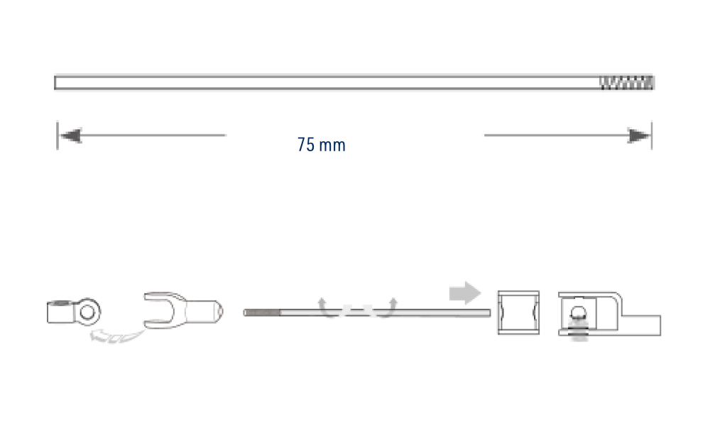
Use the dimensions below and the measurement endpoints and hole positions shown in the drawing; changing a horn or servo-arm hole changes both travel and load. Secure the retainers and check full movement without binding.
| Function | Length (mm) | Rod diameter (mm) |
|---|---|---|
| Aileron | 48 | 1.5 |
| Flap | 60 | 1.5 |
| Elevator | 52 | 1.5 |
| Rudder | 65 | 1.5 |
| Vector pitch | 85 | 1.5 |
| Vector yaw | 85 | 1.5 |
| Nose door | 41.5 | 1.2 |
| Nose-wheel steering | 75 | 1.5 |
Pre-flight preparation
Centre of gravity

Centre-of-gravity reference — view 1

Basic-flight CG: 117 mm, 5 mm forward of the moulded 122 mm line
For basic flight, use 117 mm, which is 5 mm forward of the moulded CG line. The moulded line at 122 mm is the setting for high-performance 3D flight and gives a much more sensitive pitch response. Use the basic-flight position unless you have the required 3D experience.
Check with the model completely assembled, including the selected battery, canopy and the accessories that will be flown. Keep power disconnected. Move and secure the battery to achieve the specified balance. Use the exact datum and aircraft configuration in the drawing.
Do not fly with the CG outside the specified position/range. A battery that fits physically may still prevent correct balance. Recheck after changing a battery, accessories, repairs or equipment. If the CG measurement datum or its applicability to the supplied version is uncertain, obtain confirmation before flight.
Control throws
Aileron movement
Elevator movement
Rudder movement
Flap movement
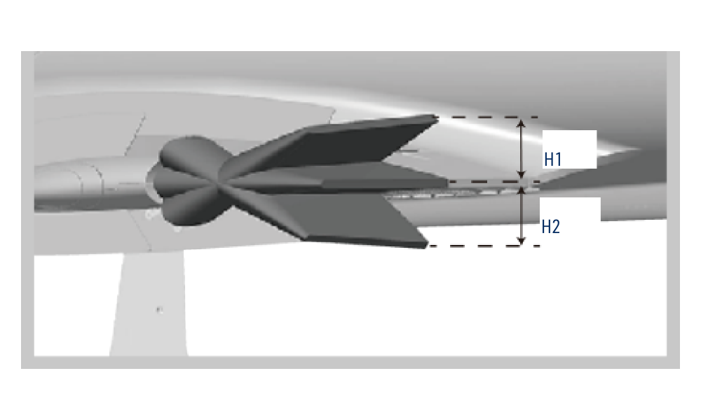
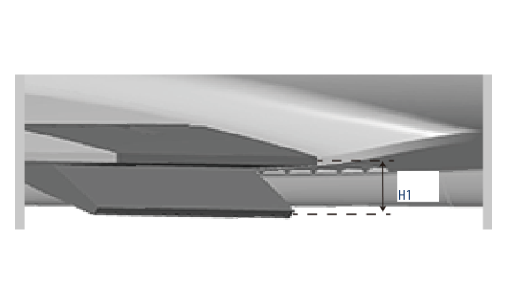
Measure each surface at the point shown in the drawing, from its specified neutral position. H1/H2 denote the two measured directions. A value given for each direction is not the total end-to-end travel. Treat transmitter percentages as reference settings; adjust the radio to reproduce the specified measured movement.
| Control | Low rate | High rate |
|---|---|---|
| Aileron, each direction | 21 mm / 80 % | 27 mm / 100 % |
| Elevator, each direction | 29 mm / 80 % | 35 mm / 100 % |
| Rudder, each direction | 31 mm / 80 % | 38 mm / 100 % |
| Flaps, down | Not specified | 31 mm |
| Thrust-vector travel | 80 % | 100 % |
Set the neutrals and any specified flap compensation in Receiver installation and radio setup before checking these throws.
„Not specified“ does not mean zero travel. Obtain a verified setting before using that switch position.
Control-direction check
Basic flight mode: Aileron — stick left
Basic flight mode: Aileron — stick right
Basic flight mode: Rudder — stick left
Basic flight mode: Rudder — stick right
Basic flight mode: Elevator — pitch up
Basic flight mode: Elevator — pitch down
Basic flight mode: Flap — flaps down
3D flight mode: Aileron — stick left
3D flight mode: Aileron — stick right
3D flight mode: Rudder — stick left
3D flight mode: Rudder — stick right
3D flight mode: Elevator — pitch up
3D flight mode: Elevator — pitch down
3D flight mode: Flap — flaps down
Check directions from behind the aircraft, with the model facing away. Test one function at a time, then combined inputs at the stick corners. Do not fly if any movement disagrees with the model’s control-direction diagram.
| Command/function | Required check |
|---|---|
| Right roll | Right aileron/elevon trailing edge up; left down. Left roll reverses these movements. |
| Pitch up | Elevator/elevon trailing edges move up; a pitch-down command reverses the movement. Check both halves and the specified neutral offset. |
| Right yaw | Rudder trailing edge moves right; steering follows the commanded turn where fitted. Check any split-drag-rudder or vector system by its own diagram. |
| Flaps | Both sides lower together to the selected setting and return fully to neutral; verify the specified elevator compensation. |
| Retracts | Gear and doors complete their intended sequence without binding; extended gear is secure. Support the model with the wheels clear. |
Compare all moving surfaces with the drawing.
Pre-flight checks
- Confirm that all adhesives are cured, fasteners are secure and the wing/tail attachments are locked. Pull-check removable wings and inspect hinges, horns, ball links and clevis retainers.
- Confirm the CG, neutral positions, control throws, correct model memory and directions. Check every flight mode and any gyro, vectoring, flap, sweep or retract function fitted.
- Carry out a range test and failsafe test following the radio instructions, with propulsion disabled. Do not fly if the radio link or failsafe is unreliable.
- Check that batteries are charged, securely retained and undamaged. Confirm connector polarity, canopy retention and that no cable can reach the propulsion or moving mechanisms.
- Inspect the propulsion for damage or foreign objects. Verify that the cooling path is open and that a controlled motor check produces no abnormal vibration.
- Check the flying area, weather, runway/landing area and the position of other people. Have an experienced pilot check the initial setup.
Maiden flight and landing
Make the maiden flight in calm, suitable conditions at an established model-flying site. Use the initial CG and high-rate throws specified for this model. Plan a short flight with reserve battery capacity.
High rates are recommended for the maiden flight to keep the full specified control travel available if unexpected trim or handling problems require larger corrections. Program a comfortable amount of exponential (expo) to soften the response around stick centre while retaining full control-surface travel at the stick limits. Where expo values are given in this manual, use them as a starting point and check the sign convention on your transmitter. High rates and expo do not compensate for an incorrect CG or mechanical setup; complete all balance and control checks before flying.
Climb to a safe height before trimming or testing a different rate or flap setting. Make one adjustment at a time.
Use a clear runway suited to the model and its wheels. Take off into wind, keep the wings level and avoid pulling into a steep climb before the model has flying speed. Check any flap compensation at safe altitude before using it on approach. Land into wind and reduce throttle before touchdown.
Shutdown
- Stop the motor, enable throttle cut and keep the transmitter on.
- Disconnect all flight batteries before switching off the transmitter or retrieving the model for maintenance.
- Remove the battery, allow the battery and power system to cool, and inspect the airframe and propulsion.
- Store LiPo packs at the storage state specified for the battery. Do not leave a battery connected inside the model.
Appendix
Maintenance and transport
Inspect the model after every flight and particularly after a hard landing. Check foam joints, joiners, hinges, control horns, retaining screws, linkages, retract mounts and electrical connectors. Replace damaged propulsion parts; do not try to fly out a vibration. Repairs must restore alignment, strength and free control movement. Repeat the balance, control and range checks after repairs.
Clean with a soft cloth and materials compatible with the foam and paint. Keep moisture out of electronics and bearings. Remove fragile scale fittings for transport, protect the controls from pressure and support the airframe without distorting it. Disconnect batteries before removing wings or unplugging connectors.
Troubleshooting
| Symptom | Checks before further operation |
|---|---|
| Motor does not arm | Disconnect power. Check the correct model memory, receiver binding, throttle minimum/trim, throttle cut, battery condition and connector polarity. If fitted, check that reverse is in the required startup position. Consult the installed ESC’s error indications. |
| Motor starts unexpectedly or runs in the wrong direction | Disconnect power immediately. Check throttle direction, failsafe and wiring with propulsion disabled. Do not change motor connections while the battery is attached. |
| Surface moves incorrectly or binds | Check the labelled plugs, transmitter mixes/reversing, servo-arm/horn holes and linkage geometry. Check the entire range and combined commands; repeat gyro direction checks. |
| Vibration or loss of power | Stop and disconnect the battery. Inspect the rotor/propeller, fasteners, bearings, intake and cooling path. Check the battery within its specified operating limits and replace damaged components. |
| Pitch changes when flaps deploy | Recheck CG, neutral positions, symmetric flap travel and the specified elevator mix. Adjust only after a safe-height test; do not conceal an incorrect mechanical setup with excessive trim. |
| Gear or doors fail to complete their sequence | With power disconnected, inspect wiring and obstructions. Support the model for a controlled test and keep fingers clear. Do not repeatedly drive a jammed mechanism. |
Warranty and post-warranty service
All Freewing products are covered by a 2-year warranty covering all manufacturing defects and faults. When making a claim within the warranty period, please always present a copy of the proof of purchase with the product and provide the service personnel with as detailed and complete information as possible about the defect found, your usage and other information that will facilitate the assessment of the claim and speed up its settlement. Please make your claim at the shop where you purchased the product.
This warranty certificate entitles you to a free warranty repair of the product supplied by KAVAN Europe s.r.o. within a period of 24 months. The warranty does not cover natural wear and tear due to normal use, as this is a product for modelling use, where the individual parts operate under much higher loads than normal toys are subjected to.
The warranty also does not cover any part of the equipment that has been improperly installed, roughly or improperly handled, or damaged in an accident, or any part of the equipment that has been repaired or altered by an unauthorised person (this includes the application of any waterproof sprays/coatings by the user). Like other fine electronics products, do not expose this equipment to high temperatures, low temperatures, moisture, dusty environments, violent mechanical shocks and impacts. Do not leave it in direct sunlight for extended periods of time.
Improper installation includes inadequate mounting, mechanical strain on cables and insufficient cooling.
Please claim warranty repairs from the shop where you purchased the product.
If possible, use the original packaging when returning the product for service. Include a dated description of its use and the fault, together with your full address and telephone number.
Recycling (European Union)
Electrical equipment bearing the crossed-out bin symbol must not be disposed of in normal household waste. Instead, it must be taken to a specialised collection and recycling facility. In EU (European Union) countries, electrical equipment must not be disposed of in normal household waste (WEEE - Waste of Electrical and Electronic Equipment, Directive 2012/19/EU). You can take unwanted equipment to your nearest collection or recycling centre. The equipment will then be disposed of or recycled safely, free of charge. By handing in your unwanted equipment, you can make an important contribution to protecting the environment.
EU Declaration of Conformity
Dongguan Freewing Electronic Technology Co., Ltd. hereby declares that the model Freewing Ares 3D 1156 mm and the equipment supplied with it comply with the applicable European Union requirements. The full text of the EU Declaration of Conformity is available at www.kavanrc.com/doc.