Translations:KAVAN Bristell B23 1600mm - Instruction manual/17/de: Difference between revisions
Mrs. Kavan (talk | contribs) No edit summary |
Mrs. Kavan (talk | contribs) No edit summary |
(No difference)
| |
Latest revision as of 09:20, 6 May 2024
- Trocken, ohne zu kleben stecken Sie das Seiten- und Höhenleitwerk in die Ausschnitte im Rumpf (siehe Abb. 2+3). Stellen Sie sicher, dass die Teile gut passen und das Höhen- und Seitenleitwerk senkrecht zueinander stehen (Abb. 4). Wenn es nötig ist, schleifen Sie die Teile vorsichtig.
- Verbinden Sie das Seitenruderservokabel mit dem Verlängerungskabel im Rumpf (RUDD) und sichern Sie die Stecker mit einem Schrumpfschlauch, Binden mit einer Zahnseide oder Kleben mit einem Klebeband. Tragen Sie einen mittelflüssigen oder lieber dicken Sekundenkleber, bzw. einen klaren Klebefüller auf die Kontaktfläche an der Flosse auf und bringen Sie das Seitenleitwerk an. (Abb. 2)
- Verbinden Sie das Höhenruderservokabel mit dem Verlängerungskabel im Rumpf (ELEV) und sichern Sie die Stecker mit einem Schrumpfschlauch, Binden mit einer Zahnseide oder Kleben mit einem Klebeband. Tragen Sie einen mittelflüssigen oder lieber dicken Sekundenkleber, bzw. einen klaren Klebefüller auf die Kontaktfläche an der Flosse auf und bringen Sie das Höhenleitwerk an. (Abb. 3)
- Noch vor dem Aushärten des Klebers überprüfen Sie wieder, dass das Höhenund Seitenleitwerk senkrecht zueinander steht. (Abb. 4)
- Stecken Sie die Flügelhälften an den Rohr-Verbinder. Die Kabel von Querruderservos, Klappen und LED Lichtern führen Sie auf die obere Seite des Flügels. (Abb. 5)
- Führen Sie die Kabel von Servos und LED Lichtern in den Rumpf in den Kabinenraum und bringen Sie den Flügel an den Rumpf an. Platzieren Sie das Hauptfahrwerk an den Flügel und befestigen Sie es zusammen mit dem Flügel an den Rumpf mit zwei selbstschneidenden Schrauben 3,0×40 mm. (Abb. 6)
- Stecken Sie das Bug-Fahrwerksbein in die Konsole im Rumpf ein, entfernen Sie die Kabinenabdeckung, befestigen Sie den Steuerhebel an dem hervorstehenden Ende und sichern Sie ihn mit einer Stellschraube M3×10 mm. (Abb. 7+8+9)
- Setzen Sie den Propeller auf die Welle des Mitnehmers und sichern Sie ihn mit einer Mutter und einer Unterlage. Die Mutter ziehen Sie mit dem Schraubenschlüssel Nr. 10 fest an. (Aus Sicherheitsgründen ist es besser, den Propeller am Schluss zu montieren, wenn Sie sich nach dem Anschluss des RC-Sets vergewissert haben, dass sich der Motor in die richtige Richtung bewegt). Befestigen Sie den Propellerspinner mit der Schraube M2,5×22 mm (Abb. 10).
- Kleben Sie ein Klettband (einen Teil mit den Schlaufen, ist nicht im Baukasten enthalten) auf die Unterseite Ihres Akkus und sichern Sie den Akku mit dem Klettband im Kabinenbereich. (Abb. 11)
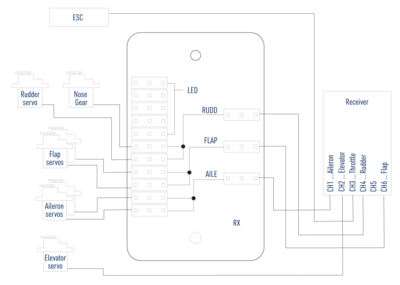
B23 - Receiver connection - Nehmen Sie die Abdeckung der Anschlussplatte ab und schließen Sie Ihren Empfänger gemäß dem Schema rechts an. Befestigen Sie den Empfänger mit den angeschlossenen Servos und dem Drehzahlregler mit einem Klettband oder einem doppelseitigen Schaumstoffklebeband im hinteren Teil der Kabine. Positionieren Sie die Antennen so, dass ihre aktiven Teile im 90 Grad Winkel zueinander stehen (wenn Sie einen Diversity-Antennenempfänger haben).Hinweis: Standardmäßig werden die Querruder-, Klappen-, Seitenruder- und Bugbeinservos über eine spezielle Anschlussplatte im Modell an den Empfänger angeschlossen, so dass auch die einfachsten 6-Kanal-RC-Sets zur Steuerung des Modells verwendet werden können. Wenn Sie die Querruder und Klappen unabhängig voneinander steuern wollen, wie dies bei fortschrittlicheren Computer-RC-Sets möglich ist, muss die Anschlussplatte durch ein Viererpack 25–30 cm lange Verlängerungskabel ersetzt werden.
Die LED Lichter werden nur von der Anschlussplatte versorgt, sie werden in keiner Weise ferngesteuert. (Abb. 12) - Schalten Sie den Sender ein und ziehen Sie den Gashebel ganz nach unten, erst dann können Sie die Antriebsbatterie an den Drehzahlregler anschließen. Kalibrieren Sie den Gasbereich des Drehzahlreglers gemäß der Bedienungsanleitung. Stellen Sie alle Ruder mit allen Bedienelementen und Trimmhebeln in der Neutrallage in Mittelstellung. Ziehen Sie dann die Schrauben der Gestängeverbindungen und Servoarme an. (Abb. 8+9)
- Bringen Sie die Kabinenhaube an.
- Mit einem mittelflüssigen Sekundenkleber kleben Sie die Antennen-Scales (Abb. 13) und die Pitotrohre (Abb. 14).
