Translations:KAVAN Bristell B23 1600mm - Instruction manual/17/sk: Difference between revisions
Mrs. Kavan (talk | contribs) (Created page with "# Zatiaľ na sucho, bez lepenia zasuňte zvislú a vodorovnú chvostovú plochu do výrezov v trupe '''(viď obr. 2+3)'''. Uistite sa, že diely dobre lícujú a vodorovná a zvislá chvostová plocha sú navzájom kolmé '''(obr. 4)'''. Ak je treba, diely opatrne zabrúste. # Kábel serva smerovky prepojte s predlžovacím káblom v trupe (RUDD) a konektory zaistite zmršťovacou bužírkou, previazaním dentálnou niťou alebo prelepením samolepiacou páskou. Na styč...") |
Mrs. Kavan (talk | contribs) (Created page with "# Zatiaľ na sucho, bez lepenia zasuňte zvislú a vodorovnú chvostovú plochu do výrezov v trupe '''(viď obr. 2+3)'''. Uistite sa, že diely dobre lícujú a vodorovná a zvislá chvostová plocha sú navzájom kolmé '''(obr. 4)'''. Ak je treba, diely opatrne zabrúste. # Kábel serva smerovky prepojte s predlžovacím káblom v trupe (RUDD) a konektory zaistite zmršťovacou bužírkou, previazaním dentálnou niťou alebo prelepením samolepiacou páskou. Na styč...") |
(No difference)
| |
Latest revision as of 13:16, 8 October 2024
- Zatiaľ na sucho, bez lepenia zasuňte zvislú a vodorovnú chvostovú plochu do výrezov v trupe (viď obr. 2+3). Uistite sa, že diely dobre lícujú a vodorovná a zvislá chvostová plocha sú navzájom kolmé (obr. 4). Ak je treba, diely opatrne zabrúste.
- Kábel serva smerovky prepojte s predlžovacím káblom v trupe (RUDD) a konektory zaistite zmršťovacou bužírkou, previazaním dentálnou niťou alebo prelepením samolepiacou páskou. Na styčnú plochu na kýlovke na neste stredné alebo radšej husté sekundové lepidlo popr. číry lepiaci tmel a zvislú chvostovú plochu usaďte na miesto. (Obr. 2)
- Kábel serva výškovky prepojte s predlžovacím káblom v trupe (ELEV) a konektory zaistite zmršťovacou bužírkou, previazaním dentálnou niťou alebo prelepením samolepiacou páskou. Na styčnú plochu naneste stredné alebo radšej husté sekundové lepidlo popr. číry lepiaci tmel a vodorovnú chvostovú plochu usaďte na miesto. (Obr. 3)
- Ešte pred vytvrdnutím lepidla znovu skontrolujte, že vodorovná a zvislá chvostová plocha sú navzájom kolmé. (Obr. 4)
- Poloviny krídla nasuňte na trubkovú spojku; káble serv krídelok, klapiek a LED svetiel vyveďte na hornú stranu krídla. (Obr. 5)
- Káble serv a LED svetiel zaveďte do trupu do priestoru kabíny a krídlo usaďte na trup. Na krídlo umiestnite hlavný podvozok a spolu s krídlom ho upevnite k trupu dvoma samoreznými skrutkami 3,0×40 mm. (Obr. 6)
- Prednú nohu zasuňte do konzoly v trupe, odoberte kryt kabíny, na vyčnievajúci koniec nasaďte ovládaciu páku a zaistite ju nastavovacou skrutkou M3×10 mm. (Obr. 7+8+9)
- Na hriadeľ unášača nasaďte vrtuľu a zaistite ju maticou s podložkou, ktorú pevne dotiahnite kľúčom č. 10. (Z bezpečnostných dôvodov je ale vhodnejšie ponechať montáž vrtule až nakoniec, keď po zapojení RC súpravy overíte, že sa motor otáča v správnom zmysle. ) Kužeľ vrtule upevnite pomocou skrutky M2,5×22 mm. (Obr. 10)
- Na spodnú stranu vášho akumulátora nalepte pásik suchého zipsu (časť so slučkami; nie je súčasťou stavebnice) a akumulátor upevnite pásikmi suchého zipsu v priestore kabíny. (Obr. 11)
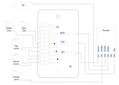
B23 - Receiver connection - Odstráňte kryt zapojovacej dosky a váš prijímač zapojte podľa schémy vpravo. Prijímač s pripojenými servami a regulátorom otáčok upevnite v zadnej časti kabíny pomocou pásika samolepiaceho suchého zipsu alebo obojstrannej samolepiacej pásky s penovou vrstvou a antény umiestnite tak, aby ich aktívne časti boli na seba navzájom kolmé (ak máte prijímač s diverzitnými anténami).Pozn.: V základnom prevedení sa servá krídielok, klapiek, smerovky a prednej nohy pripájajú do prijímača pomocou špeciálnej zapojovacej dosky nainštalovanej v modeli, čo umožňuje pre ovládanie modelu používať aj tie najjednoduchšie šesťkanálové RC súpravy. Pokiaľ chcete používať nezávislé ovláda nie krídielok a klapiek, aké umožňujú pokročilejšie počítačové RC súpravy, je zapojovaciu dosku nutné nahradiť štvoricou 25–30 cm predlžovacích káblov.
LED svetlá sú iba napájané zo zapojovacej dosky; nie sú nijako diaľkovo ovládané. (Obr. 12) - Zapnite vysielač, ovládač plynu stiahnite úplne dolu - až potom môžete pripojiť pohonný akumulátor k regulátoru otáčok. Vykonajte kalibráciu rozsahu plynu regulátora otáčok podľa návodu na jeho obsluhu v prílohe. So všetkými ovládačmi a trimami v neutráli nastavte do stredovej polohy všetky kormidla.
- Nasaďte kryt kabíny.
- Stredným sekundovým lepidlom prilepte makety antén (obr. 13) a Pitotovej trubice (obr. 14).
