
Translations:KAVAN Bristell B23 1600mm - Instruction manual/17/cs: Difference between revisions
Mrs. Kavan (talk | contribs) Created page with "# Zatím na sucho, bez lepení zasuňte svislou a vodorovnou plochu do výřezů v trupu '''(Obr. 2+3)'''. Ujistěte se, že díly dobře lícují a vodorovná a svislá ocasní plocha jsou navzájem kolmé '''(Obr. 4)'''. Je-li třeba, díly opatrně zabruste. # Kabel serva směrovky propojte s prodlužovacím kabelem v trupu (RUDD) a konektory zajistěte smršťovací bužírkou, převázáním dentální nití nebo přelepením samolepící páskou. Na styčnou plochu..." |
Mrs. Kavan (talk | contribs) No edit summary |
||
| Line 6: | Line 6: | ||
# Kabely serv a LED světel zaveďte do trupu do prostoru kabiny a křídlo usaďte na trup. Na křídlo umístěte hlavní podvozek a spolu s křídlem jej upevněte k trupu dvěma samořeznými šrouby 3,0×40 mm. '''(Obr. 6)''' | # Kabely serv a LED světel zaveďte do trupu do prostoru kabiny a křídlo usaďte na trup. Na křídlo umístěte hlavní podvozek a spolu s křídlem jej upevněte k trupu dvěma samořeznými šrouby 3,0×40 mm. '''(Obr. 6)''' | ||
# Příďovou nohu zasuňte do konzole v trupu, sejměte kryt kabiny, na vyčnívající konec nasaďte ovládací páku a zajistěte ji stavěcím šroubem M3×10 mm. '''(Obr. 7+8+9)''' | # Příďovou nohu zasuňte do konzole v trupu, sejměte kryt kabiny, na vyčnívající konec nasaďte ovládací páku a zajistěte ji stavěcím šroubem M3×10 mm. '''(Obr. 7+8+9)''' | ||
# Na hřídel unašeče nasaďte vrtuli a zajistěte ji maticí s podložkou, kterou pevně dotáhněte klíčem č. 10. (Z bezpečnostních důvodů je ale vhodnější ponechat montáž vrtule až nakonec, když po zapojení RC soupravy ověříte, že se motor otáčí ve správném smyslu.) Kužel vrtule upevněte pomocí šroubu | # Na hřídel unašeče nasaďte vrtuli a zajistěte ji maticí s podložkou, kterou pevně dotáhněte klíčem č. 10. (Z bezpečnostních důvodů je ale vhodnější ponechat montáž vrtule až nakonec, když po zapojení RC soupravy ověříte, že se motor otáčí ve správném smyslu.) Kužel vrtule upevněte pomocí šroubu M2,5×22 mm. '''(Obr. 10)''' | ||
M2,5×22 mm. '''(Obr. 10)''' | # Na spodní stranu vašeho akumulátoru nalepte pásek suchého zipu (část se smyčkami; není součástí stavebnice) a akumulátor upevněte pásky suchého zipu v prostoru kabiny. '''(Obr. 11)''' [[File:B23 - Receiver connection.png|B23 - Receiver connection|right|frameless|400x400px]] | ||
# | |||
# Remove the connection board cover and hook up your receiver, servos and ESC following the wiring diagram right. The receiver is to be secured with a strip of double-sided foam tape or hook–and–loop tape to the rear part of the cockpit. Deploy the antennas, so their active parts are square to each other (if you are using a receiver featuring diversity antennas).<br>{{Note|type=info|text='''Note:''' The kit is supplied with the connection board for ailerons, flaps, rudder and the steerable nose gear, so you can use even the most basic 6-channel radios to control your Bristell B23. If you intend to use independent control of aileron and flap servos and an advanced computer radio, you will have to replace the default Y-cables with four 25–30 cm extension cables.}}<br>The LED lights are only powered via the connection board. They are not remotely controlled in any way. | # Remove the connection board cover and hook up your receiver, servos and ESC following the wiring diagram right. The receiver is to be secured with a strip of double-sided foam tape or hook–and–loop tape to the rear part of the cockpit. Deploy the antennas, so their active parts are square to each other (if you are using a receiver featuring diversity antennas).<br>{{Note|type=info|text='''Note:''' The kit is supplied with the connection board for ailerons, flaps, rudder and the steerable nose gear, so you can use even the most basic 6-channel radios to control your Bristell B23. If you intend to use independent control of aileron and flap servos and an advanced computer radio, you will have to replace the default Y-cables with four 25–30 cm extension cables.}}<br>The LED lights are only powered via the connection board. They are not remotely controlled in any way. | ||
# With your radio on, set the servos to the neutral position (sticks and trims centred) and fasten the setting screws of the pushrod connectors on the elevator and rudder servo arms. Perform the throttle range calibration of the ESC as described in the attachment of this manual. | # With your radio on, set the servos to the neutral position (sticks and trims centred) and fasten the setting screws of the pushrod connectors on the elevator and rudder servo arms. Perform the throttle range calibration of the ESC as described in the attachment of this manual. | ||
# Attach the canopy. | # Attach the canopy. | ||
# Use medium cyano to glue the dummy antennas '''(Fig. 13)''' and pitot tube. '''(Fig. 14)''' | # Use medium cyano to glue the dummy antennas '''(Fig. 13)''' and pitot tube. '''(Fig. 14)''' | ||
Revision as of 07:55, 6 May 2024
- Zatím na sucho, bez lepení zasuňte svislou a vodorovnou plochu do výřezů v trupu (Obr. 2+3). Ujistěte se, že díly dobře lícují a vodorovná a svislá ocasní plocha jsou navzájem kolmé (Obr. 4). Je-li třeba, díly opatrně zabruste.
- Kabel serva směrovky propojte s prodlužovacím kabelem v trupu (RUDD) a konektory zajistěte smršťovací bužírkou, převázáním dentální nití nebo přelepením samolepící páskou. Na styčnou plochu na kýlovce naneste střední nebo raději husté vteřinové lepidlo popř. čirý lepící tmel a svislou ocasní plochu usaďte na místo. (Obr. 2)
- Kabel serva výškovky propojte s prodlužovacím kabelem v trupu (ELEV) a konektory zajistěte smršťovací bužírkou, převázáním dentální nití nebo přelepením samolepící páskou. Na styčnou plochu naneste střední nebo raději husté vteřinové lepidlo popř. čirý lepící tmel a vodorovnou ocasní plochu usaďte na místo. (Obr. 3)
- Ještě před vytvrzením lepidla znovu zkontrolujte, že vodorovná a svislá ocasní plocha jsou navzájem kolmé. (Obr. 4)
- Poloviny křídla nasuňte na trubkovou spojku; kabely serv křidélek, klapek a LED světel vyveďte na horní stranu křídla. (Obr. 5)
- Kabely serv a LED světel zaveďte do trupu do prostoru kabiny a křídlo usaďte na trup. Na křídlo umístěte hlavní podvozek a spolu s křídlem jej upevněte k trupu dvěma samořeznými šrouby 3,0×40 mm. (Obr. 6)
- Příďovou nohu zasuňte do konzole v trupu, sejměte kryt kabiny, na vyčnívající konec nasaďte ovládací páku a zajistěte ji stavěcím šroubem M3×10 mm. (Obr. 7+8+9)
- Na hřídel unašeče nasaďte vrtuli a zajistěte ji maticí s podložkou, kterou pevně dotáhněte klíčem č. 10. (Z bezpečnostních důvodů je ale vhodnější ponechat montáž vrtule až nakonec, když po zapojení RC soupravy ověříte, že se motor otáčí ve správném smyslu.) Kužel vrtule upevněte pomocí šroubu M2,5×22 mm. (Obr. 10)
- Na spodní stranu vašeho akumulátoru nalepte pásek suchého zipu (část se smyčkami; není součástí stavebnice) a akumulátor upevněte pásky suchého zipu v prostoru kabiny. (Obr. 11)
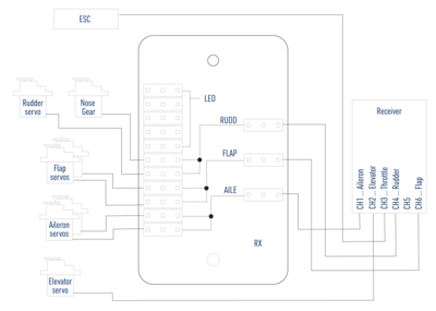
B23 - Receiver connection - Remove the connection board cover and hook up your receiver, servos and ESC following the wiring diagram right. The receiver is to be secured with a strip of double-sided foam tape or hook–and–loop tape to the rear part of the cockpit. Deploy the antennas, so their active parts are square to each other (if you are using a receiver featuring diversity antennas).Note: The kit is supplied with the connection board for ailerons, flaps, rudder and the steerable nose gear, so you can use even the most basic 6-channel radios to control your Bristell B23. If you intend to use independent control of aileron and flap servos and an advanced computer radio, you will have to replace the default Y-cables with four 25–30 cm extension cables.
The LED lights are only powered via the connection board. They are not remotely controlled in any way. - With your radio on, set the servos to the neutral position (sticks and trims centred) and fasten the setting screws of the pushrod connectors on the elevator and rudder servo arms. Perform the throttle range calibration of the ESC as described in the attachment of this manual.
- Attach the canopy.
- Use medium cyano to glue the dummy antennas (Fig. 13) and pitot tube. (Fig. 14)
