KAVAN Strike DLG - Instruction manual/en: Difference between revisions
(Updating to match new version of source page) |
(Updating to match new version of source page) |
||
| Line 10: | Line 10: | ||
Fly only on days with a light breeze and in a safe place away from obstacles. | Fly only on days with a light breeze and in a safe place away from obstacles. | ||
=== Specification === | |||
{| class="wikitable" | {| class="wikitable" | ||
|- | |- | ||
| Wingspan || 1096 mm | | Wingspan || 1096 mm | ||
| Line 23: | Line 24: | ||
| CG position || 65–70 mm | | CG position || 65–70 mm | ||
|- | |- | ||
| Controls || | | Controls || Ailerons, rudder, elevator | ||
|} | |} | ||
Revision as of 11:26, 13 May 2024
Introduction
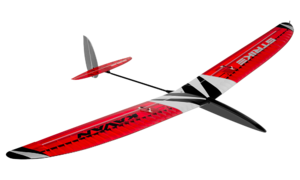
KAV02.8024 KAVAN Strike DLG
Precautions
This RC model is not a toy. Use it with care, strictly following the instructions in this manual.
Assemble this model following strictly these instructions. DO NOT modify or alter the model. Failure to do so, the warranty will lapse automatically. Follow the instructions to obtain a safe and solid model at the end of the assembly.
Children under the age of 14 must operate the model under the supervision of an adult. Assure that the model is in perfect condition before every flight, ensuring all the equipment works correctly and that the model is undamaged in its structure.
Fly only on days with a light breeze and in a safe place away from obstacles.
Specification
| Wingspan | 1096 mm |
| Length | 880 mm |
| All-up weight | 180 g |
| Wing section | YA 0801 |
| CG position | 65–70 mm |
| Controls | Ailerons, rudder, elevator |
Recommended RC equipment
- Rudder and elevator servo: KAVAN GO-6MG 2×
- Receiver battery: 1S LiPo 3.7 V 450–500 mAh
Recommended glues
Unless stated otherwise, use medium cyanoacrylate (CA) glue (#KAV56.9952 KAVAN CA Medium). Wing sheeting is better to be glued using a water-resistant white aliphatic resin, like our KAV56.9960 KAVAN White Glue (alternatively, you can use this sort of glue for most wood-to-wood joints). The highly loaded parts (wing roots, fuselage formers etc.) should be glued together using 30-minute (or slower) epoxy (like KAV56.9967 Epoxy 30min) offering high strength and enough time for the correct positioning.
Tools and Accessories
- Very sharp modeller’s knife (e.g. #KAV66.770 with No. 11 blades)
- Scissors
- Electric drill with drill bits
- Wire cutter
- Long nose pliers
- Screwdrivers
- Razor saw
- Sandpaper No. 100–120, 180–220, 360–400
- Needle files
- Soldering iron and solder
- Clothing pegs
- Modeller’s pins
- Epoxy mixing stick and vessel
- Masking tape, clear sticky tape
- Rubbing alcohol (for cleaning up excessive epoxy)
- Paper tissue or soft cloth (for cleaning up excessive epoxy)
- Straightedge with scale
- Square edge
- Thin clear plastic film (for protecting the building plan)
- Permanent marker
- Modeller’s sealing iron, heat gun (for covering)
- Lightweight balsa filler
- Hot melt glue gun & hot melt glue
Warning
This RC model you will build and fly is not a toy! Although it may seem light and slow in flight, it is capable of serious bodily harm and property damage. It is your responsibility and yours alone - to build this model correctly, properly install RC equipment and motor, test the model and fly following all safety standards (and common sense), as set down in Safety Codes valid in your country. If you are just starting RC modelling, consult your local hobby shop or an experienced modeller in your local RC club to find a good instructor.
Precautions
You must build the model according to the instructions. Do not alter or modify the model, as doing so may result in an unsafe or unflyable model. Take time to build straight, true and strong. Use proper radio and other equipment that is in first-class condition, properly install all the components and test their correct operation before the first and any further flight. Fly the model only with competent help from a well-experienced modeller if you are not already an experienced RC pilot yourself.
Model assembly
Tail Surfaces
- Trial fit the parts of the horizontal stabilizer, elevator, fin and rudder – no glue yet! Sand as necessary to obtain a perfect fit. (Fig. 1)
- Roughen the surface of the 3×0.5 mm R3 carbon spar using No. 120 sandpaper and glue it with medium CA to the trailing edge of the fin R1.
- Glue the T3 Lite Ply reinforcement plate into the horizontal stabilizer T1. Once the glue has cured sand it flush with the stabilizer.
- Sand the entire surface of the horizontal stabilizer, elevator, fin and rudder with No. 120–150 sandpaper; round the outer edges. Bevel the leading edges of the rudder and elevator referring to the Det. D-D.
- Put the tail surfaces aside for now; they will be finished after the tailplane seat is installed to the tail boom.
Fuselage
- Trial fit the parts of the fuselage - no glue yet! Sand as necessary to obtain a perfect fit. Be sure the tail boom F1 can be inserted easily but tightly into the openings in F10 and F8 formers.
- Glue the balsa reinforcement plate F2L to the inner side of the F3L fuselage left side (with the large opening for the F11 hatch); glue the plate F2R to the inner side of the F3R fuselage right side (without the hatch opening). (Fig. 2)
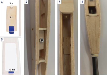
- Glue the F14 locking plate to the front of the F11 hatch; the locking plate has to match the position of a notch in the F2L reinforcement plate and the hatch matches the opening in the F3L fuselage side. The pair of F15 magnets will be epoxied into the F11 hatch and F2L plate only after the fuselage is covered, otherwise, the high temperature of your sealing iron might de-magnetize the magnets. (Fig. 4+5)
- Epoxy the M4 aluminium captive nut into the F9 fuselage brace. Do not forget bevelling the edges of the fuselage formers and braces where required. (Fig. 6+3)
- Epoxy the fuselage formers and braces F10, F9, F8, F6 first into one fuselage side from the rear to the nose and then attach the other side. Put the fuselage straight bottom side onto the building plan protected by a sheet of thin clear plastic film and check the fuselage is true and straight - pin down as necessary until the glue sets.
- Epoxy the F4 former in place, bevelled F5 nose balsa block and the F17 and F18 cross braces too.
- Epoxy the tow hook plate F7 in place. (Fig. 7)
- Partially cut (ca 0.5–1 mm deep) and crack the fuselage sides along the F10 fuselage former (the cut line is to be soaked with thin CA before the final sanding). Slide the tail boom tube F1 onto the openings in F8 and F10 formers – do not glue yet.
- Slide the F21 Lite Ply tail boom fairing ring onto the tail boom F1; tack glue the fuselage sides to the ring (be sure not to glue the tail boom yet). Glue the top and bottom balsa plates F20 and F19 in place. (Fig. 8)
- Glue the three piece upper F13a, F13b, F13c and F16 lower 2.5 mm balsa sheeting to the fuselage.
- Sand the entire fuselage (with the F11 hatch in place) so the tail end including the F21 ring fits smoothly with the tail boom.
Wing
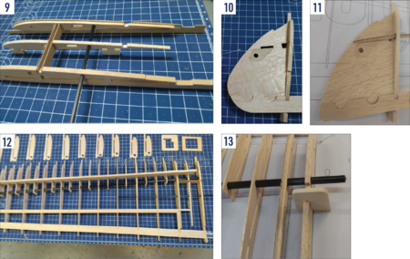
- The wing is to be built directly on the building plan protected by a thin sheet of clear plastic film. The wing ribs and riblets are supplied with jig tabs on the bottom side to allow building the wing with an under-cambered profile on a flat surface; at the same time producing the washout (the wing trailing edge is higher by 3 mm at the tips than at the root) necessary for a stable flight of the model. DO NOT CUT the mounting jigs; they will be removed only after the entire wing has been built. There is also the rib spacing jig to correctly set the leading edge ends of rib and riblet mounting jigs. (Fig. 12)
- Epoxy together the wing central ribs W5 and W6; insert 3 mm beech dowels into the holes to obtain the correct match. Note: Make a left and right pair of assemblies. (Fig. 9)
- Glue the plywood reinforcement plate W39 (for the W64 DLG pin) into the wing tip W35 and then the wing tip to the trailing edge W30 on a flat working surface; glue the W36 and W37 reinforcement plates in place creating a notch for the plywood wing tip spar W38. (Fig. 10 + 11)
- Thread all the wing ribs and riblets W3 to W32 onto the main spar carbon tube W60; use a round file to trim the openings in the ribs to set the ribs at the required angle. Thread the auxiliary carbon rod spar W61 through the respective holes in the W3 to W12 ribs. (Fig. 12)
- Put the main spar with ribs onto the building plan and insert the ends of ribs into the corresponding notches in the trailing edge W44 (W45 for the right-wing half). Insert the front ends of the rib jig tabs into the corresponding notches of the rib spacing jig. Align all the parts to the correct position over the building plan; pin down where necessary and then glue the ribs W4 to W31 to the W60 main spar tube, W61 auxiliary spar and the trailing edge. Epoxy the wing tip spar W38 into the main spar tube and to the wing tip into the notch between the W36 and W37 reinforcement plates. Glue the wing tip to the W32 rib and finally, the W32 rib to the main spar and trailing edge. Glue the balsa gusset W33 between the W32 rib and the W31 riblet.
- Glue the root rib W3 using the root rib dihedral jig in place. (Fig. 13)
- Trim the notches for the leading edge W46 (3 mm beech dowel) in the ribs and riblets as necessary. Glue the leading edge (starting from the wing tip and then rib by rib towards the wing root). (Fig. 14)
- Insert the W47 rear spar and the W48 aileron leading edge into the corresponding notches in ribs W4 to W32. Align them both flush with the upper edge of the ribs but do not glue yet.
- Glue the W51 aileron servo frame together with the W52 upper cover plate between the W12 and W14 ribs from above (the opening in the frame fits KAVAN GO-06MG servos; you might have to trim it if other servos are used). Glue the aileron W62 root and W63 tip ribs in place - to the W48 aileron leading edge and W44(45) trailing edge ONLY. Glue the W50 aileron horn block between the W12 and W14 ribs; flush with the upper edge of the ribs and the W48 aileron leading edge. (Fig. 15+16)
- Glue the W34 reinforcement plate between the W30 and W32 ribs, glue the W40 and W41 reinforcements to the wing tip, and glue the two W49 gussets in place. (Fig. 17)
- Epoxy the plywood wing joiner bay plates W43 into the W3, W4 and W5/W6 ribs - be sure the bay will accommodate the W42 wing joiner nicely. (Fig. 20)
- Thoroughly check the entire wing, you are almost there; the wing sports the required 3 mm washout at the tip due to the rib mounting tabs now. Once satisfied, apply cyano to all joints. Note: The W47 rear spar and the W48 aileron leading edge are supposed to be glued to the ribs ONLY, not to each other!
- Now you can carefully cut the rib jig tabs using a sharp modeller’s knife.
- Soak the W51 aileron servo frame and W52 plate with thin cyano or thinned epoxy from the inside. Glue the W53 bottom aileron servo cover between the W12 and W14 ribs. (Fig. 18)
- Sand the bottom side of all ribs and riblets to shape with No. 120 sandpaper.
- Glue the bottom wing centre 1.5 mm balsa sheeting W57 (with a rectangular opening for the aileron servo cable) and W58 in place; glue the plywood reinforcement plate W54 on the top of W58 along the area of the wing fixing bolt. (Fig. 19+20)
- Thread a thick sewing thread through rectangular openings for the aileron servo cable in the W4 to W12 ribs and W57 bottom sheeting and secure it with pieces of sticky tape - it will help you to navigate the aileron servo cable through later.
- Glue the top wing centre 1.5 mm balsa sheeting W56 and W55 in place. Sand the wing root flush with the W3 rib - the slanted position set with the root rib dihedral jig ensures the correct wing dihedral. (Fig. 21)
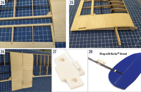
- Use a fine razor saw and modeller’s knife blade to cut through the ribs and trailing edge to separate the aileron from the wing. Bevel the aileron leading edge by 30° following the Det. A-A. Finally, sand the entire aileron smooth using No. 180 sandpaper. (Fig. 23+24)
- Assemble the other wing half in the same way.
- Sand both two wing halves with No. 120 sandpaper. Trial fit - no glue yet - the wing halves and the W42 wing joiner; insert the riblets W1 and W2 between the root ribs. Once satisfied with the fit, epoxy the W42 wing joiner, and W1 and W2 riblets to one wing half aligned to match the wing root rib. (Fig. 25)
- Put the wing half with the wing joiner glued in on your workbench (protected by a sheet of plastic film) so the alignment pin of the W1 riblet protrudes over the edge of the table; then epoxy the other wing panel. Be sure the trailing edges of both wing panels match perfectly. Double-check the correct wing halves alignment and let the epoxy set. (Fig. 26)
- Epoxy the wing bolt plate W59 to the top of the wing centre; once the glue has cured drill a 4.2 mm hole for the wing bolt through the W59. (Fig. 26)
- Now it is the time to decide which tip of the wing the discus launch pin is to be glued into - the left tip for a right-handed pilot, the right tip for a left-handed pilot. Laminate a strip of the fibreglass cloth around the hole for the discus launch pin on top and bottom of the wing tip. You can use a special low-viscosity laminating/finishing epoxy or a regular epoxy glue thinned slightly by an epoxy paint/dope thinner. Once the resin has cured, sand the entire wing smooth with No. 180 sandpaper.
Covering
- Thoroughly sand the surface of all parts with No. 360–400 sandpaper and carefully vacuum all the dust (the iron-on film does not stick well to a dusty surface; the dust also contains hard grains released off the sandpaper capable of ruining the smooth coating of your sealing iron quickly).
- Use as light iron-on film, as you can get (transparent KAVAN iron-on film, Oracover®, Oralilight® etc. – not supplied in the kit). Follow the instruction manual supplied with the covering film of your choice please.
Final Assembly
Hinging the Control Surfaces
- Use high-quality hinging tape strips (available in hobby shops) or strips of the same iron-on film you used for the covering. Remember to apply the tape with the control surface deflected to the limit (refer to Det. D-D) to get free movement of the particular control surface.
Fuselage and Tail
- Using a very sharp pointed modeller’s knife, cut the covering film over the opening for the tailplane pylon in the horizontal stabilizer, over slots for the Kevlar® thread in the fin and over control horn slots in the elevator and rudder.
- Use a fine needle file to trim the pre-cut slots for the horizontal tailplane pylon, fin, and elevator and rudder push rod exits in the carbon tube tail boom. Use a fine round needle file to make a groove for the rudder push rod tube in the tailplane pylon F22. (Fig. 27)
- Insert the tailplane pylon F22 into the F1 tail boom - no glue yet. Insert the fin and rudder assembly into the notch at the end of the tail boom and tack glue it to the tail boom. Bind the fin to the tail boom with a Kevlar® thread threaded through the slots in the fin. (Fig. 28)
- Slide the horizontal stabilizer on the F22 tailplane pylon; align it square to the fin and to the longitudinal axis of the tail boom and tack glue it to the pylon. Double-check the correct alignment; once satisfied, apply a generous amount of cyano along all the joints and onto the Kevlar® thread. Insert the elevator and rudder push rod outer tubes into the tail boom. Secure them with a piece of polyurethane foam soaked with epoxy that you will work into the centre of the tail boom with a thin stick. This is great for a precise, pushrod backlash-free elevator and rudder control. (Fig. 29)
- The F12 servo mount supplied in the kit has been tailored for the recommended KAVAN GO-6MG servos. Whatever type of servos you use, always check if the openings don’t need trimming first. We recommend soaking the edges of the servo openings with cyano. Once satisfied, glue the F12 servo mount in place (the servos are to be fitted in the upside-down position). (Fig. 30)
- Thread the protruding ends of the elevator and rudder push rod outer tubes through the holes in the F6 former so the tubes lead directly to the horns of servos in the F12 servo mount. Insert the tail boom into the fuselage - no glue yet. (Fig. 31)
- Attach the wing to the fuselage and secure it with the M4 bolt. Looking from above, front and rear check the fuselage and tail boom are straight and the wing dihedral makes a nice symmetrical "V" in relation to the horizontal stabilizer. Once satisfied cut the push rod outer tubes to the correct length and epoxy thoroughly the tail boom into the fuselage. Double-check the correct alignment before the glue sets.
- Solder the M2 brass threaded couplers on one end of the 0.8mm piano wire push rods. Screw the ball links on and slide the push rods into the respective outer tubes. Secure the ball links to both two servo arms with the M1.6 screws supplied in the kit. Insert the fibreglass control horns into the slots in the elevator and rudder - do not glue yet. Set the servos to the neutral with your radio on; attach the servo arms square to the side of the servo case. Set the elevator and rudder flush with the horizontal stabilizer resp. fin. Mark the correct length of the push rods and bend them to the right angle (you can make a "Z-bend", but the simple L-bend usually works well enough). Insert the L-bends into the holes in the control horns and cyano the horns into the elevator and the rudder in place, set in the neutral position. Finally, secure the servos with drops of hot-melt glue, silicone or MS polymer glue in the servo tray. (Fig 29+32)
- Epoxy the pair of F15 magnets into the F11 hatch and fuselage. Double-check their polarity - they have to cling to each other! For easy removal, apply a strip of folded sticky tape to the rear edge of the hatch. (Fig. 4+5)
- Install your receiver into the fuselage, under the wing. The receiver battery will go into the nose.
Wing
- Thoroughly epoxy the carbon discus-launch pin into the left (for a right-handed pilot) or right (for a left-handed pilot) wing tip. (Fig. 33)
- Remove the covering film over the openings for the aileron servo arms in the W52 top cover plates and in the W53 bottom cover plate. Install aileron servos with arms fitted (set them to neutral with your radio on), aileron horns and linkage the same way you did with the rudder and elevator. Finally, using a piece of sticky or iron-on film seal the opening in the W53 bottom cover plates. (Fig. 34+35)
Tow Hook
- Install the tow hook into one of the pre-drilled holes in the F7 tow hook plate; it should be positioned about 5 mm in front of the centre of gravity. (Fig. 36)
Recommended Control Surface Throw, CG Position
- CG Position: 74–78 mm
- Rudder: ±25 mm
- Elevator: ±10 mm
- Ailerons: 10 mm up, 6 mm down
- Ailerons as the airbrake: 40 ° down
- Discus launch configuration: rudder -1 mm against the direction of the launch (right-handed - rudder 1 mm right), elevator 1 mm down.Note: Use this configuration for the climbing phase of the discus launch only after the model has been trimmed out properly and you‘ve made yourself familiar with the controls.)
- Airbrake → elevator mix: elevator 2 mm down at full airbrake.
Flying
Be sure you are using fully charged batteries. Now (and before any further flight) check the correct function of the whole radio equipment, motor and moving of control surfaces. Be sure any part of flight equipment cannot move during flight. We strongly recommend making a range check (see your radio instruction manual for details).
The first flight: Wait for a calm day. Fly only on a safe site such as an RC club flying field. Glider will be very happy on your favourite slope on a calm day. The very light lift will allow perfect fine trimming out.
Switch your transmitter and then the receiver on and check all the working systems once more. Facing INTO the wind hold your transmitter in one hand; grip the model in the other hand near the centre of gravity. Hold it at head level and give the model a fairly powerful push exactly into the wind; wings level, nose slightly down. Your model should now glide in a long, flat and straight path, without needing any help from you. Use the controls gently if necessary, and adjust the trim tabs until your STRIKE DLG glides the above-described way. Now check the position of control surfaces; set the length of pushrods to bring back trim tabs on your transmitter to the central position if necessary (we strongly recommend doing it in any way). Check again the gliding of your STRIKE DLG.
Now you are ready to make your first discus launch.
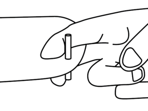
Discus Launch
The discus launch allows your model to reach quite a high altitude without much effort. Like with any "sports performance", it will require some training to do it right. Our step-by-step manual makes it easy. We will describe the procedure for a right-handed pilot; with the launching pin attached to the left wingtip. The "left-handed" procedure is the mirror image.

Position A - Getting ready
Your right index and middle fingers should be wrapped around the launch pin at the left wing tip. Your thumb is to be gently pressed against the leading edge of the wing. Stand with your left shoulder into the wind and the right wing tip pointing at ca 45° angle to the ground.

Position B - The first step
Take a long step with your left foot pulling the STRIKE DLG up and forward with your right arm.

Position C - Rotation
Start rotating to the left keeping the STRIKE DLG flat and your right arm extended.

Position D – Continued rotation
The second half of the rotation - the most important part for a good launch. Do not use too much arm in this section. Just let the swing of your torso speed the STRIKE DLG up.

Position E - Release
By this time in the launch the plane will be trying to climb on its own. Just release your fingers and let the plane fly out of your hand directly into the wind.
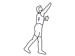
Position F – Taking the control
Catch your balance; watch your STRIKE DLG climb whilst getting hold of your radio, ready to control your model. The plane will climb after release – the climb angle should be shallow at first; once you are well acquainted with the discus launch you can use more force and increase the launch angle to 60–80 degrees. When completely familiar and comfortable you can add two quick steps before starting the turning sequence, to get some extra speed and energy.
When the plane has slowed almost to the point of stopping push full down elevator to achieve level flight. When this is done at the right moment the plane will go into horizontal flight with just enough airspeed to maintain a gentle glide. If it is done too early the plane will pitch up her nose dangerously after a short dive. If it is done too late the plane will stall.
Go catch some thermals and enjoy your new STRIKE DLG.
Parts list
| Main parts | |||
|---|---|---|---|
| Part | Quantity | Building plan no. | Material |
| Building Plan 1:1 | 1 | ||
| Instruction Manual | 1 | ||
| Sheet of Stickers | 1 | ||
| Pushrod set | 2 | Plastic tube + 0.8mm piano wire | |
| Tail boom | 1 | F1 | Carbon tube Ø7/6 mm |
| Rib Spacing Jig | 1 | Balsa 1.5 mm | |
| Bag no. 1 - small parts | |||
| Tow hook | 1 | Metal | |
| Magnet Ø3 mm | 2 | F15 | Neodymium |
| Wing Bolt M4 | 1 | Nylon | |
| Captive nut M4 | 1 | Aluminium | |
| Rudder Horn | 4 | Fibreglass 1.5 mm | |
| Ball link short M2 | 4 | Balsa 1.5 mm | |
| Threaded coupler M2/0.8mm | 2 | Brass | |
| Rudder and elevator servo tray | 1 | F12 | Balsa 4 mm |
| Carbon pin | 1 | Ø5 mm | |
| Fibreglass cloth | 1 | 110 g/m² | |
| Kevlar ® Thread | 1 | ||
| Quicklink | 2 | ||
| Quicklink pin | 2 | ||
| Aileron push rod | 2 | Carbon rod Ø2 mm | |
| Bag no. 2 | |||
| Nose block | 1 | F5 | Balsa 10 mm |
| Servo hatch | 1 | F11 | Plywood 1.2 mm |
| Fuselage Former | 1 | F6 | Plywood 3 mm |
| Fuselage Formers | 1+1+1 | F4+F8+F10 | Lite Ply 3 mm |
| Fuselage cross-brace | 1+1 | F17+F18 | Lite Ply 3 mm |
| Fuselage hatch lock | 1 | F14 | Lite Ply 3 mm |
| Tail boom fairing ring | 2 | F21 | Lite Ply 3 mm |
| Wing riblet | 1 | W2 | Lite Ply 3 mm |
| Root rib dihedral jig | 1 | Lite Ply 3 mm | |
| Nose Shape Template | 1 | Lite Ply 3 mm | |
| Bag no. 3 | |||
| Wing rib | 2 | W6 | Plywood 0.8 mm |
| Wing centre sheeting reinforcement | 2 | W54 | Plywood 0.8 mm |
| Wing joiner bay plate | 4 | W43 | Plywood 0.8 mm |
| Towhook plate | 1 | F7 | Plywood 2 mm |
| Wing captive nut brace | 1 | F9 | Plywood 2 mm |
| Wing bolt plate | 1 | W59 | Plywood 2 mm |
| Wing tip spar | 2 | W38 | Plywood 2 mm |
| Wing riblet | 1 | W1 | Lite Ply 3 mm |
| Wing joiner | 1 | W42 | Lite Ply 3 mm |
| Wing tip reinforcement plate | 2 | W39 | Lite Ply 1.5 mm |
| Bag no. 4 - tail | |||
| Horizontal stabilizer | 1 | T1 | Balsa 2.5 mm |
| Elevator | 1 | T2 | Balsa 2.5 mm |
| Horizontal stabilizer reinforcement plate | 1 | T3 | Balsa 2.5 mm |
| Fin | 1 | R1 | Balsa 2.5 mm |
| Rudder | 1 | R2 | Balsa 2.5 mm |
| Carbon fin reinforcement | 1 | R3 | Carbon strip 0.5×3 mm |
| Tailplane pylon | 1 | F22 | |
| Bag no. 5 | |||
| Wing rib | 2 | W6,8,10,12,14,16,18,20,22,24,26,28 | Balsa 1.5 mm |
| Wing riblet | 2 | W7,9,11,13,15,17,19,21,23,25,27,29,31 | Balsa 1.5 mm |
| Wing root rib | 2 | W3 | Balsa 4 mm |
| Wing tip rib | 2+2 | W30, W32 | Balsa 4 mm |
| Wing rib | 2+2 | W4, W10 | Balsa 3 mm |
| Trailing edge | 1+1 | W44, W45 | Balsa 3×15 mm |
| Leading edge | 2 | W46 | Beech dowel Ø3 mm |
| Wing tip reinforcement (bottom) | 2+2 | W36,W37 | Balsa 4 mm |
| Wing tip reinforcement (top) | 2+2 | W40, W41 | Balsa 4 mm |
| Wing tip | 2 | W35 | Balsa 1.5 mm |
| Gusset | 4 | W49 | Balsa 1.5 mm |
| Wing main spar | 2 | W60 | Carbon tube Ø6/5 mm |
| Auxiliary spar | 2 | W61 | Carbon tube Ø3 mm |
| Rear spar | 2 | W647 | Balsa 4 mm |
| Aileron leading edge | 2 | W48 | Balsa 4 mm |
| Aileron root/tip rib | 2+2 | W62, W63 | Balsa 4 mm |
| Aileron servo frame | 2 | W51 | Balsa 4 mm |
| Aileron servo top cover plate | 2 | W52 | Balsa 1.5 mm |
| Aileron servo bottom cover plate | 2 | W53 | Balsa 1.5 mm |
| Aileron horn block | 2 | W50 | Balsa 4 mm |
| Wing centre sheeting | 2+2+2+2 | W55, W56, W57, W58 | Balsa 1.5 mm |
| Bag no. 6 | |||
| Fuselage side | 1+1 | F2L/R | Balsa 1.5 mm |
| Fuselage bottom sheeting | 1 | F16 | Balsa 2.5 mm |
| Fuselage upper sheeting | 1+1+1 | F13a, b, c | Balsa 2.5 mm |
| Fuselage side reinforcement plate | 1+1 | F2L/R | Balsa 3 mm |
| Tail boom fairing | 1+1 | F19, F20 | Balsa 2.5 mm |
