XuHuai X100 – Instruction manual
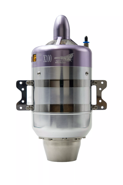
XuHuai X100
Introduction
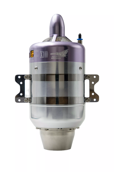
The XuHuai X100 is a micro turbojet engine for unmanned radio-controlled model aircraft. It uses a single-stage centrifugal compressor, a single-stage turbine, ceramic bearings lubricated by oil mixed into the fuel, a ceramic igniter and a brushless starter. The FADEC electronic control unit (ECU) is built into the engine. An external brushless gear pump supplies fuel, and the Ground Support Unit (GSU) provides the setup and monitoring interface.
The ECU controls the engine through starting, running and cooling. Automatic control does not replace correct installation, a reliable fuel and electrical supply, or continuous supervision. Read the complete manual before installation or operation. Keep it with the engine and pass it to any subsequent owner.
This engine is not a toy. Incorrect installation or operation can cause fire, serious injury and property damage. It is intended only for unmanned RC models. Never use it in manned equipment. Operation requires knowledge of model gas turbines.
Contact your supplying dealer or KAVAN technical/service staff if any instruction is unclear or if your hardware or GSU differs from this manual. Do not resolve an uncertain connection or setting by trial and error.
Technical specifications
Performance figures refer to standard atmospheric pressure and an ambient temperature of 15 °C. Do not change factory ECU limits to match the specification table.
| Parameter | Value |
|---|---|
| Model | XuHuai X100 |
| Diameter | Ø90 mm |
| Overall length | 213 mm |
| Net engine weight | 1020 g |
| Maximum thrust | 100 N |
| Idle thrust | 5 N |
| Idle speed | 50 000 rpm |
| Rated maximum speed | 160 000 rpm |
| Approximate fuel consumption | 350 g/min; operating point not specified |
| Exhaust temperature specification | 750 °C (specification figure; not an alarm or shutdown threshold) |
| Engine battery | 3S LiPo, 11.1 V nominal, 2200 mAh, at least 25C; maximum 12.6 V |
| Receiver supply | Separate 2S LiPo, 7.4 V nominal; verify equipment voltage ratings |
| Fuel and lubricating oil | Jet A-1 or diesel; Mobil Jet Oil II at 5 % of the fuel quantity |
| Service interval | 25 operating hours |
The approximate 350 g/min consumption figure has no specified operating point or test conditions. It is not a guaranteed maximum-thrust consumption value.
Fuel consumption is stated in g/min, not ml/min. Do not convert it without the actual fuel density. Establish practical endurance for the installation, including starting, taxiing, landing and a reserve. Net engine weight is not the complete installed-system weight.
The engine uses an external electronically controlled brushless pump and a high-speed brushless starter. Futaba, Jeti and FrSky telemetry are listed for the series; check the required interface and compatibility with the actual radio and firmware before connection.
The 750 °C specification figure is not an ECU alarm or shutdown threshold. The operating EGT range is 300–900 °C; reaching 900 °C requires engine inspection before further operation. See Exhaust gas temperature.
The oil quantity is 5 % of the fuel quantity, not of the final mixture. Confirm the mass/volume measuring method before preparing fuel; see Fuel and lubrication.
Set contents

- XH engine with FOD protection screen.
- External electronically controlled brushless fuel pump matched to the engine model.
- GSU handheld display.
- Main wiring harness and fuel-pump wiring harness.
- Festo fuel filter.
- Fuel tubing.
- Ball valve.
- Instruction documentation.
Check the delivered set before installation. Report damage or missing items to the supplier. Retain the original packaging for service transport.
Do not interchange fuel pumps between XH engine models. Never power the pump directly from an external three-phase supply; this can destroy its driver electronics.
Required equipment
- A suitable RC aircraft installation or secure turbine test stand, with a compatible mounting arrangement.
- Suitable fuel tank, venting and filling equipment; a UAT/air-trap tank where required by the installation.
- Approved fuel and dedicated turbine lubricating oil as described below.
- A dedicated 3S LiPo engine battery, 2200 mAh, at least 25C, and a suitable charger.
- An independent 2S LiPo receiver supply, 7.4 V nominal. Check receiver, servo and power-distribution compatibility.
- A radio system with a latching throttle-cut control and configurable failsafe.
- Fuel-compatible tubing, fittings and any installation components needed beyond the supplied set.
- A suitable rigid exhaust duct/tailpipe where the aircraft installation requires one.
- A CO₂ fire extinguisher of at least 2 kg, eye protection and hearing protection.
- Fuel-handling gloves, a suitable fuel collection container and materials for cleaning spills.
No UAT capacity, tubing bore, filter micron rating or aircraft tank capacity is specified in the supplied series information. Obtain suitable components through the engine/airframe supplier; do not infer a required size from a generic drawing.
Safety notes and warnings
Meaning of the safety boxes
DANGER identifies hazards that can cause serious injury, fire or substantial property damage. ATTENTION identifies precautions against equipment damage or incorrect operation. NOTE gives supporting information. These labels do not reduce the importance of any instruction.
Operating area and supervision
Run the engine only outdoors in an open area. Never run it in a room, garage or other enclosed space. Keep spectators, children and animals more than 10 m from the engine. Keep the intake and exhaust unobstructed and keep people and combustible material out of the exhaust stream.
Secure the aircraft or test stand against thrust before starting. Wear eye and hearing protection during starting and testing. Keep the extinguisher immediately accessible. Do not hold a running turbine or rely on a person holding the aircraft as the restraint. Use a trained assistant. Do not leave an energised or running engine unattended. Carry out initial testing on a suitable test stand before flight installation.
The 10 m figure is a spectator separation requirement, not a defined safe exhaust length. The manufacturer has not supplied separate dimensional intake, exhaust or rotor-fragment safety zones.
Fire and hot surfaces
Exhaust gas and engine surfaces can remain dangerously hot after shutdown. Keep fuel, clothing, hands and equipment clear. Keep a CO₂ extinguisher of at least 2 kg at the operating site. Avoid dry-powder extinguishers for engine use because powder can permanently damage the turbine. This equipment-protection precaution must never delay necessary firefighting, evacuation or the protection of people.
For a fire or uncontrolled fuel release, command throttle cut if safely accessible, keep people clear and follow the site's emergency response procedure. Do not approach a burning engine to preserve equipment or complete a normal cooling cycle. The normal shutdown instructions assume that the equipment can remain safely powered.
Intake and foreign objects
Leave the FOD protection screen fitted during operation. Intake suction can draw in loose objects and clothing. Never test suction with your hand or place fingers or tools near the intake. Before each run, remove loose screws, stones, grass, packaging and other debris from the engine bay and operating area.
Fuel and electrical work
Handle and store fuel according to its safety data sheet and local site rules. Wear suitable gloves. Keep it away from ignition sources and hot surfaces. Clean spilled fuel before starting. Do not fill or disconnect the fuel system while the engine is running. Do not refuel a hot installation.
Check polarity before connecting batteries. Reverse polarity can destroy the ECU and pump. Isolate electrical supplies before installation work or connector changes. During normal shutdown, leave the engine supply connected until the automatic cooling cycle finishes.
Main section
Fuel and lubrication
Fuel selection
Use Jet A-1 aviation turbine fuel as the preferred fuel. Diesel is also permitted, but can give slower starting and acceleration and more exhaust smoke. Do not use heating oil or substitute another fuel without manufacturer confirmation.
Lubricating oil
Use dedicated turbine lubricating oil at 5 % of the fuel quantity, not 5 % of the final mixture. The specified oil is Mobil Jet Oil II. Do not substitute conventional two-stroke oil, hydraulic oil or an unidentified oil.
The bearings receive lubricant through the fuel mixture. Incorrect oil or mixture can damage the bearings and engine. Do not run on unlubricated fuel.
Calculate the oil quantity against the fuel quantity. Before mixing, obtain the supplier’s measuring instructions for the specified oil; do not assume that a mass percentage and a volume percentage are interchangeable.
Use a clean, compatible container and mix thoroughly. Label the fuel and oil used and record the preparation date. Filter fuel and keep containers closed against contamination. Do not use fuel containing sediment or visible contamination.
Fuel system

Layout and components
The basic delivery path is tank / optional UAT → supplied filter → matched fuel pump → engine. Use the installation-specific connection instructions for the supplied ball valve. Install the supplied filter upstream of the pump and place the pump as close to the fuel supply as practical, while respecting the line requirements below. Follow the actual pump's inlet and outlet identification.
Use the supplied or supplier-approved fuel-system components. Fully seat each connection. Route tubing without kinks, pinching, chafing or contact with hot components. Keep the tank vent unobstructed. Secure the system so aircraft movement cannot pull out a line.
Do not use silicone tubing anywhere in the fuel system. Do not use ordinary Tygon tubing on the pressurised pump-to-engine side. Do not use nylon cable ties on fuel lines. Use the intended fittings and retention method.
Use the supplied filter and the correct replacement specified by the supplier. Do not add restrictions to compensate for contaminated fuel.
Line length and height difference
| Item | Manufacturer information |
|---|---|
| Factory setup reference, pump inlet side | 75 cm |
| Factory setup reference, pump outlet side | 75 cm |
| Pump outlet / pressure line minimum | 50 cm |
| Recommended upper length, each inlet and outlet line separately | Preferably no more than 1 m each |
| Maximum height difference, pump to engine | 1 m |
Do not shorten the pump outlet line below 50 cm. An excessively short line can increase fuel pressure, cause flame ejection during starting and create a risk of flameout during acceleration.
The 75 cm + 75 cm dimensions describe the manufacturer's factory test setup. They are not a requirement to shorten both lines as far as possible.
The recommended 1 m upper length applies separately to the inlet and outlet lines, not to their combined length. The maximum 1 m height difference is measured between the pump and engine.
Filling and air removal
Fill with clean, correctly mixed fuel using compatible equipment. Check the tank, vent, filter, pump, valve and all connections for leakage. Before starting, the delivery lines must be filled and free of visible air bubbles. Persistent bubbles require investigation of the pickup, tank/UAT, seals and inlet connections.
The GSU includes a manual prime/test function. Do not use it indiscriminately: pumping fuel into an unlit engine can create a wet start. Obtain the approved priming procedure for the installed engine and firmware before using this function. Do not use another engine’s pump-test or prime settings.
Power supply

Engine supply
Use a dedicated 3S LiPo battery, 11.1 V nominal, 2200 mAh, at least 25C. The supply must not exceed 12.6 V. Starting current can peak at 20–30 A. Do not use ordinary lithium-ion batteries for this supply.
A battery showing an acceptable voltage at rest may still suffer excessive voltage drop during starting. Check its condition, charge and connectors. Do not keep attempting starts with inadequate power: failed ignition can leave fuel inside the engine.
Receiver supply
Use a separate 2S LiPo receiver supply, 7.4 V nominal. Do not share the engine battery as the receiver supply or connect the 3S engine battery to the receiver supply input.
The receiver, servos and any power-distribution or regulation equipment must be compatible with the actual battery voltage throughout its charge range. A nominal 7.4 V label is not a receiver or servo voltage rating.
Wiring and isolation
Use the original harnesses. Do not cut, substitute or extend engine/GSU signal wiring. Obtain a manufacturer-supplied longer harness if necessary. Route and secure cables away from heat, fuel, sharp edges and moving parts. Confirm connector orientation and polarity before applying power.
Keep the engine battery connected through normal automatic cooling. Disconnect batteries after the session once cooling has finished. The ECU draws standby current; a connected 2200 mAh pack may be depleted over 1–2 months.
Engine installation
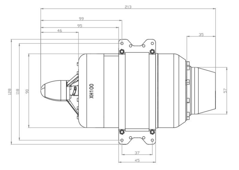
- Check the engine, FOD screen, bracket, harnesses and fuel components for transport damage.
- Use the original mounting bracket. Install the engine with the logo uppermost and fuel connection downward. Do not install it upside down.
- Secure the mounting to an airframe or stand suitable for the engine's thrust and thermal environment. Use the mounting supplier’s fastener and tightening instructions.
- Provide an unobstructed intake. The intake duct minimum internal diameter must be no smaller than the engine casing diameter. Retain the FOD screen. This diameter requirement alone is not a complete intake design specification.
- For a tailpipe installation, retain a 25 mm gap between engine exhaust outlet and tailpipe. Use a rigid tailpipe that cannot be crushed or collapse. Use the installation-specific instructions to identify the measurement points. If they are unclear, contact the supplier before running the engine.
- Install the fuel system and independent electrical supplies as described above. Leave access for inspection and disconnection after cooling.
- Check inside the airframe for loose debris. Move and gently shake the unpowered airframe to help reveal residual debris before starting.
- Complete commissioning and a secure ground test before flight.
Use installation-specific tailpipe dimensions, mounting torques and thermal clearances. If the 25 mm gap cannot be identified unambiguously on your hardware, obtain clarification before running.
Radio control and failsafe

Display layout and wording may vary with firmware. Values shown in the illustration are examples, not settings to copy.
Throttle and cut
Connect the receiver throttle output using the supplied receiver lead and the designated signal connection for the actual harness. Confirm port labels before powering up. If a connection is unclear, contact the supplier before applying power.
Assign throttle cut to a latching control, not a spring-return switch. Verify which position commands engine stop. In this manual, CUT means the engine-stop command is active; RUN/IDLE enabled means the cut has been released and the calibrated idle/start command is available. Switch direction and displayed transmitter wording vary.
Failsafe
Set receiver failsafe to command engine shutdown on loss of signal. Do not use „Hold“. Signal loss must trigger engine shutdown within 2 seconds. This refers to the shutdown response, not a claim that the rotor or cooling motor stops within 2 seconds.
Verify failsafe configuration and the cut command before the first live run. Arrange a controlled ground verification of the actual engine shutdown response with the aircraft restrained, the exhaust area clear and an experienced turbine operator present. Use the radio manufacturer's prescribed signal-loss test method. Do not fly until the response has been verified.
Throttle calibration
- With the engine secured for the commissioning procedure, open RC Learn / Study RC / throttle calibration on the GSU.
- Register Min as the stop command, Idle as the idle-enabled command, and Max as full throttle, following the prompts for the installed firmware.
- Check that each transmitter command produces the intended GSU indication before initiating a start.
- Complete the required successful start test without interrupting power after calibration. Calibration is not effective without this test; if power is interrupted, repeat calibration.
- Where the GSU continues with RC Learn / RC Learning / RC Successful, follow the live commissioning sequence below. Follow the prompts for the fitted firmware; contact the supplier if the expected confirmation does not appear.
Do not copy numerical transmitter endpoints or switch direction from another installation.
The ECU supports linear and exponential throttle curves. Use exponential response for aircraft with a high thrust-to-weight ratio. No universal curve setting is specified. Confirm the fitted ECU's available settings before changing them.
GSU and ECU

Display layout and wording may vary with firmware. Values shown in the illustration are examples, not settings to copy.
Connect the GSU for commissioning, starting, troubleshooting and monitored shutdown. The ECU remains in the engine; removing the GSU does not remove engine control. The GSU may be removed for flight. Use the approved connection arrangement and do not disconnect other harness components while removing the display.
Menu wording can vary with language and firmware. Where the main screen uses the XUHUAI logo as its menu button, tap the logo to open the menu.
| Menu | Function |
|---|---|
| Study RC / RC Learn | Throttle command calibration |
| Start / Start Up | Pump voltage, ignition speed, preheat speed and clutch-disengagement settings |
| Run | Acceleration, deceleration, maximum and idle speed settings |
| Engine Data / Engine Parameters | Runtime, starts, speed/temperature records and graphs; available fields depend on firmware |
| Test | Individual pump, ignition-valve and starter functions |
| Other | Pump power, temperature correction, manual priming, factory reset and language options |
Parameter changes
Use the model's supplied settings. This manual describes throttle calibration and the confirmed ACC/DEC guidance. Do not change ignition, valve, clutch, pump-limit, temperature-calibration or speed-limit values merely because the menu exposes them. Contact the supplier for a fault requiring changes outside the documented procedure.
Do not copy another model’s numerical defaults or change settings marked „Do not modify“.
Fault information and Factory Reset
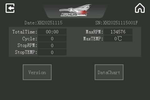
Display layout and wording may vary with firmware. Values shown in the illustration are examples, not settings to copy.
The current ECU does not save fault data. Record the displayed message when safe; do not rely on a recoverable shutdown history.
Photograph the displayed message and write down the circumstances while the information is available, without delaying a necessary safety action. Engine-data screens or operating graphs are not proof of persistent fault logging.
Factory Reset restores factory defaults and may affect the engine setup. Do not use it as a routine troubleshooting step. Record visible settings and contact service first.
Commissioning
Before the first live start

Display layout and wording may vary with firmware. Values shown in the illustration are examples, not settings to copy.
Complete this check with the installation secured and the starting area clear:
- Confirm engine model, matched pump and correct supplied harnesses.
- Record the engine serial number and visible ECU/GSU firmware information.
- Confirm mounting orientation, FOD screen, intake path and tailpipe installation.
- Confirm approved fuel/oil preparation, a clean supply, secure leak-free lines and no visible bubbles.
- Confirm the outlet line is at least 50 cm, each inlet/outlet line follows the recommendation of no more than 1 m, and pump-to-engine height difference does not exceed 1 m.
- Confirm charged, correctly connected independent engine and receiver supplies.
- Confirm throttle cut, signal mapping and failsafe configuration.
- Connect the GSU and confirm the self-check shows no fault.
- Have the CO₂ extinguisher ready and clear the operating area.
Calibration during the first run
- Start using Normal start below and allow the engine to reach stable idle.
- For a new engine, smoothly advance to full throttle, watching the GSU and engine response.
- Wait for Cal-Pump to disappear. Then hold the setting for 10 seconds, before slowly returning to idle.
- If completing RC calibration, also confirm the required successful RC-learning indication. The learning sequence may display RC Learn at idle, RC Learning when full throttle is commanded and RC Successful when completed. Firmware may present these differently; do not assume Cal-Pump and RC learning are the same operation.
- Abort the test if an abnormal condition occurs. Do not continue to satisfy a timer through overheating, fire, vibration or a fault.
- Complete a normal shutdown and cooling cycle. Inspect for leakage, loose components or thermal damage before proceeding to flight testing.
If pump calibration does not complete, no expected RC confirmation appears, or the engine cannot run reliably through the required throttle range, stop and obtain support.
Normal start
Do not start if fuel has accumulated inside the engine, fuel is leaking, the battery supply is inadequate, a fault remains unresolved or the operating area is unsafe. Complete the failed/wet-start procedure before another attempt.
- Restrain the aircraft or test stand. Complete the pre-start checks above, including line inspection and battery charge.
- Set the throttle stick to minimum and apply CUT before enabling the system. Check the GSU self-test and displayed state.
- When ready to start, release CUT to the calibrated idle/start-enabled state. Confirm Ready on the GSU. If the state does not match the command, stop and resolve the calibration/control issue.
- Move throttle to maximum, hold for 2 seconds, then return directly to the calibrated idle command. This triggers the automatic start sequence.
- Monitor the entire sequence: igniter preheating, starter drive, fuel delivery and ignition, EGT rise, acceleration/main-fuel transition, starter clutch disengagement and stable idle.
- Confirm stable idle (Run IDLE / Idling.., depending on firmware) with no fault, fuel leak or abnormal sound before increasing thrust.
Do not repeatedly retrigger an unsuccessful start or interrupt normal automatic cooling. If starting fails, command stop and follow Failed or wet start. A normal start display is not permission to ignore visible fire, accumulated fuel or abnormal engine behaviour.
Normal stop and cooling
- Return throttle to minimum and apply CUT.
- Confirm that the engine shuts down and the ECU enters automatic cooling. The starter drives the rotor during this process.
- Keep the engine and receiver supplies connected and the intake/exhaust clear; do not interrupt any power needed by the installed control system. Monitor Cooling.. / Cooling....
- Shutdown completes when exhaust temperature is below 80 °C. Wait for the automatic cycle to finish; do not disconnect power simply because combustion has stopped.
- Once cooling is complete, disconnect the batteries. Keep clear of surfaces that may remain hot, then inspect and secure the equipment for storage.
Do not stop the engine by unplugging its battery during normal operation. Interrupting automatic cooling can damage the bearings. An electrical fault or fire requires the fault/emergency response instead of blindly maintaining power.
Failed or wet start
- Command stop with throttle minimum and CUT. Confirm the start/fuel-delivery attempt has stopped. Keep the area clear.
- Observe whether excess fuel is present. Check for fuel at the exhaust and in the installation. If you cannot determine whether fuel has accumulated, do not assume the engine is dry.
- If no excess fuel is present: another start is permitted after the cause of failure has been checked and the equipment is otherwise ready.
- If excess fuel is present: remove it before any restart. Tilt the engine nose/front downward to drain accumulated fuel. Carry this out only after moving parts have stopped, the engine has cooled and the installation is safely supported, collecting fuel in a suitable container. Obtain service assistance if safe drainage cannot be performed with the installed engine.
- Clean spills and inspect for air bubbles, inadequate battery voltage, loose connections and the indicated fault. Correct the cause before another attempt.
- Re-run the complete pre-start check. Do not restart if fuel remains, a fault persists or abnormal heat/fire has caused suspected damage.
Do not try to burn off accumulated fuel by starting. Replacing a weak battery and immediately trying again can ignite fuel left by the previous attempt. Drain excess fuel first.
Allow an active automatic cooling cycle to complete under normal safe conditions. Do not handle a hot or moving engine to perform drainage. Restart only after checking fuel accumulation, correcting the cause and completing the pre-start checks.
ACC and DEC settings
ACC controls acceleration response and DEC controls deceleration response. Higher values produce faster response on the documented 0–100 scale. Use the installed firmware’s scale and the model’s supplied settings; do not copy another engine’s defaults.
The required settings depend on atmospheric pressure, altitude and ambient temperature:
| Condition | Confirmed guidance |
|---|---|
| Altitude above 1000 m | Set both acceleration and deceleration below 50 % |
| Ambient temperature in the stated 25–40 °C guidance band | Set both acceleration and deceleration below 70 % |
„Below“ means less than the stated value, not equal to it. If both conditions apply, both requirements must be met; this means below 50 %.
For conditions outside the listed guidance, or if the appropriate setting at a boundary is unclear, obtain manufacturer guidance before operation. Do not extrapolate an ACC/DEC setting curve. Altitude concerns the atmospheric conditions at the operating site; it is not a permitted height above the launch point.
These values are guidance limits, not guaranteed stable settings for every installation. Ground-check starting, acceleration and deceleration after an authorised change. Do not change idle speed, maximum speed or other protection parameters to compensate for unexplained flameout.
The 15 °C specification test condition is not an ambient operating limit. The settings above do not define a complete permitted ambient-temperature range.
Exhaust gas temperature
The engine operating EGT range is 300–900 °C. If EGT reaches 900 °C, the engine must be inspected before further operation. This range does not apply to an unlit engine, the beginning of a start or cooling after shutdown.
If EGT reaches 900 °C, end the run and arrange engine inspection before further operation. Excessive temperature can deform the turbine wheel and cause high-speed rotor failure. Do not continue running at 900 °C because it appears as the upper endpoint of a range.
For EGT Warn / Temp high / EGT High, immediately reduce throttle to reduce engine temperature. If temperature remains abnormal or operation is unstable, command shutdown when safe and follow the inspection/fault procedure. After shutdown and safe cooling, inspect the installation, including the tailpipe gap, and obtain service assistance as required.
For EGT Low during intended stable running, investigate abnormal combustion and fuel delivery/mixture. Do not raise temperature by arbitrarily increasing pump or ignition settings.
Do not rely on automatic overtemperature shutdown. A temperature warning may occur without automatic shutdown. Reduce throttle immediately and follow the shutdown and inspection instructions.
The 750 °C specification figure is not an ECU alarm setting. Do not use it to infer the ECU’s internal protection thresholds.
Abnormal operation and flameout
On the ground
Command cut for uncontrolled flame, serious leakage, abnormal vibration or other unsafe operation. Keep people clear and use the site emergency response if necessary. For non-emergency faults, allow normal cooling when safe, record the display and inspect the external fuel/electrical installation after shutdown. Do not continue cycling the engine through the same failure.
Do not run an engine with suspected foreign-object damage, rotor rubbing, crash damage, water ingress or damage following overheating. Contact service. Do not dismantle the engine, pump or ECU to investigate internal damage.
In flight
Fly the aircraft first. Treat loss of thrust as a power-off condition and prepare a safe glide and landing. Do not rely on an automatic restart to recover the situation. A Restart Err indication means the attempted restart failed; do not keep attempting airborne restarts.
After landing, prevent another start, deal with any immediate hazard and record the available message and conditions. Check fuel remaining, bubbles, leaks, battery condition and wiring. Do not fly again until the cause is identified and corrected; repeated or unexplained faults require service assessment.
Auto Restart
Leave Auto Restart disabled: detailed conditions and operating instructions for this function are not available. Obtain supplier assistance if its state cannot be verified. Do not rely on Auto Restart to recover from a flameout.
Treat an in-flight loss of thrust as a power-off condition and prepare a safe glide and landing. An available glide time alone does not establish that an automatic restart can succeed.
Appendix
GSU operating states
The following table lists the displayed operating states, including Bunner... They are status messages rather than fault codes. A status message does not override visible abnormal operation.
| Display | Meaning |
|---|---|
| Ready | Standby; start can be initiated |
| Ready start | Preparing to start |
| Start.. | Starter operation begins |
| Bunner.. | Ignition stage; igniter operating |
| Success | Ignition successful |
| Preheat1.. / Preheat2.. / Preheat3.. | Preheat stages |
| Preheat Success | Preheating complete |
| CTH... | Starter clutch preparing to disengage |
| Idling.. | Stable idle |
| Acc.. | Accelerating |
| Dec.. | Decelerating |
| Speed.. | Steady intermediate speed |
| Max Speed... | Maximum-throttle operation |
| RC learn | Throttle learning |
| RC learning.. | Throttle calibration in progress |
| RC Success | Throttle calibration complete |
| Cooling.. / Cooling... | Automatic cooling; retain power under normal safe conditions |
| Restart / Restart... | Automatic restart sequence active; see Auto Restart |
Run IDLE and Cal-Pump are also used during starting and commissioning. RC Successful is a variant of the calibration-completion message. Display wording can differ with firmware; these spelling variants are not additional fault codes.
Troubleshooting and error codes
The actions below are ground checks after a safe stop, except where an immediate operating action is stated. Stop repeated attempts, record the visible message and contact the supplier if a fault persists. Do not remove guards, probe moving parts or dismantle internal assemblies. The current ECU does not retain fault data for later retrieval.
| Display | Meaning | Action |
|---|---|---|
| Volt Low | Insufficient supply voltage | Check charge, battery condition and connectors; use a correctly specified charged pack. After a failed start, check for accumulated fuel before retrying. |
| Volt High | Excessive supply voltage | Disconnect power immediately. Isolate the unsafe supply; do not continue operating with it. Verify the correct battery and maximum 12.6 V engine supply. Do not preserve a cooling cycle by retaining an overvoltage source. |
| RPM Low | Speed too low during starting | Check battery and external starter connections. Suspected excessive rotor resistance requires service; do not force the rotor or repeat starts. |
| Igniter Err | Igniter fault | With power isolated, check accessible harness connections. Refer a defective igniter for service. |
| StartMotor Err | Starter fault | Check accessible starter wiring after isolation. Do not force repeated starts. |
| Pump Err | Pump operation/communication fault | Check the correct pump, harness, connections and tubing for kinks or obstruction. Do not drive the pump from an external three-phase source. |
| Ignition Fail | Ignition temperature not established | Check battery, igniter connections and air in the fuel supply. Remove accumulated fuel before another attempt. |
| Preheat Time | Preheat timeout | Check fuel supply and igniter condition; apply the failed/wet-start procedure before retrying. |
| Clutch Time | Clutch-disengagement timeout | Check battery and starter condition; obtain support if persistent. Do not change clutch settings as a routine remedy. |
| Idle Time | Stable idle not established | Check for air in the fuel system. Ask service to verify the model's idle settings; do not copy another model's values. |
| Flameout1 | Flameout during steady running | Check fuel delivery, bubbles and supply voltage after landing/stopping. |
| Flameout2 | Flameout during acceleration | Check fuel delivery and apply confirmed ACC reduction guidance. Investigate the installation if it recurs. |
| Flameout3 | Flameout during deceleration | Check for fuel-system air and have the idle settings verified. Review DEC against the confirmed ambient/altitude guidance. |
| Restart Err | Automatic restart failed | In flight, continue as a power-off glide; do not repeatedly attempt airborne restarts. Investigate after landing. |
| EGT Warn / Temp high / EGT High | High exhaust temperature | Immediately reduce throttle. Check the tailpipe gap after safe shutdown. End the run and obtain inspection if 900 °C is reached; do not sustain full power through a warning. |
| EGT Low | Low exhaust temperature / abnormal combustion | Check fuel supply and mixture. Do not guess a pump or ignition adjustment. |
| OverCurrent1 | Overcurrent protection | Disconnect power. With power isolated, inspect accessible wiring for shorts; suspected pump/starter seizure requires service. |
| Power limit ! | ECU output limitation | Investigate the underlying temperature or voltage warning. Do not raise limits to defeat protection. |
Symptoms without a usable fault message
| Symptom | Check before further use |
|---|---|
| Repeated start flame ejection | Accumulated fuel, battery weakness, outlet line shorter than 50 cm, fuel supply and installation. Ask service about any required start-parameter adjustment. |
| Persistent bubbles or intermittent flameout | Tank pickup/vent, UAT if fitted, inlet connections, leaks, filter and tubing restrictions. |
| Slow start with large voltage drop | Battery condition and rating, connector contact and original harness integrity. |
| Failure after changing settings | Record the changes and contact service. Do not immediately use Factory Reset or load another engine’s settings. |
| Noise, vibration or suspected rotor contact | Do not restart. Arrange inspection. |
Start pump voltage and valve settings can affect flame ejection. Do not adjust them to compensate for accumulated fuel, inadequate batteries or incorrect plumbing. Contact service before changing start parameters.
Maintenance
Before and after operation
Before every run, inspect the FOD screen, intake, mounting, accessible wiring and fuel system. Check for loose components, fuel leaks, bubbles, contamination and damage. After each flight/session and safe cooling, inspect harnesses and tubing for ageing or damage and remove loose external dust and debris. Keep contamination out of the engine and fuel system.
Disconnect batteries after cooling. Keep the engine and components dry and protected during transport and storage. Do not add a preservative to the engine without manufacturer guidance.
Scheduled service
Arrange service at 25 operating hours. Arrange service with the supplier before continued operation beyond this interval. Service covers the bearings, seals and rotor balance; bearing replacement may be included. Confirm the required work and quotation for your engine.
Do not dismantle the engine, fuel pump or ECU. Disturbing rotor balance can damage the engine. Suspected crash, foreign-object, water or overtemperature damage requires assessment even if the routine service interval has not elapsed.
Keep a simple independent operating record, including runtime, starts, service and faults observed. This supports maintenance planning where ECU fault history is unavailable.
| Date | Runtime added / total | Fuel and oil | Observations / displayed message | Service or setting change |
|---|
| | | | | |
Service and warranty
Obtaining assistance
Contact your supplying seller for a fault or claim. Provide the engine model and serial number, proof of purchase where available, a description of the fault and any displayed error message. Useful diagnostic information includes firmware version, approximate runtime, fuel/oil details, battery details, ambient conditions, ACC/DEC settings and clear installation photographs.
Do not dismantle the engine or send it directly to the manufacturer without arrangements. Agree the return route and packing instructions first. Follow the carrier's requirements for fuel residues and batteries; do not ship a fuel-filled system.
Statutory consumer rights
Consumers have statutory rights against the seller for goods that do not conform to the contract. Applicable national law determines those rights and remedies. A manufacturer's commercial warranty is additional and does not replace or restrict them. A 25-hour service recommendation or manufacturer's warranty limit does not itself end statutory rights.
Where statutory remedies apply, they are provided free of charge under the applicable law. Commercial warranty shipping-cost clauses do not override your rights to applicable free-of-charge statutory remedies.
Manufacturer commercial warranty
Any additional commercial warranty is governed by the guarantee statement supplied with your purchase. Contact your seller for the applicable terms and claim procedure. A commercial warranty does not replace or restrict your statutory rights against the seller.
Routine maintenance and repairs outside applicable statutory or commercial coverage may be chargeable. Agree the scope and cost with the service provider before work begins.
Disposal
Collect waste fuel and oil through an appropriate waste collection service. Do not pour them into drains or onto the ground. Keep batteries and electrical equipment separate from household waste and use suitable collection facilities.