KAVAN Plus Regler - Bedienungsanleitung
Einführung
Programmierbare elektronische Fahrtregler für Brushless Motoren
Glückwunsch zum Kauf eines elektronischen Fahrtreglers für Brushless Motoren aus der KAVAN PLUS Linie. Die KAVAN PLUS Linie Regler sind Stand der Technik und decken die meisten elektrogetriebenen Modelle, die von“ Sonntagsfliegern“ geflogen werden ab. Alle Regler können schnell mit dem Sender programmiert werden und noch einfacher mit der optional erhältlichen KAVAN PRO Karte.
Warnugen
- Lesen Sie alle Anleitungen der Antriebseinheiten und des Modells und vergewissern Sie sich, daß die Antriebs Konfiguration stimmt.
- Vergewissern Sie sich, daß alle Leitungen und Verbindungen gut isoliert sind bevor Sie den Regler anschliessen, da ein Kurzschluss den Regler zerstören würde. Vergewissern Sie sich, daß alle Einheiten richtig angeschlossen sind um schlechte Verbindungen zu vermeiden, da Kontrollverlust des Modells die Folge sein könnte, oder Beschädigungen der Antriebseinheiten die Folge sein könnten. Falls notwendig verwenden Sie einen Lötkolben mit genug Leistung um alle Eingangs- und Ausgangsleitungen und Verbindungen zu verlöten.
- Blockieren Sie den Motor nie bei Vollgas, da der Regler dabei zerstört werden könnte und auch der Motor Schaden nehmen kann.Hinweis: Nehmen Sie den Gas Knüppel in die Leerlauf/Stop-Stellung oder stecken Sie sofort den Antriebsakku ab, wenn der Motor blockiert wurde.
- Verwenden Sie den Regler nie in heißer Umgebungstemperatur. Stoppen Sie die Verwendung wenn der Regler extrem heiß geworden ist. Hitze aktiviert den Regler Temperatur Schutz oder kann auch zur Beschädigung des Reglers führen.
- Stecken Sie immer nach Gebrauch den Antriebsakku ab, da der Regler immer Strom verbraucht solange der Akku angesteckt ist. Dies kann zur kompletten Entleerung der Batterie und in Folge der Zerstörung derselben führen. Dies würde keine Garantie darstellen.
Eigenschaften
- Der Regler mit 32-bit Micro Prozessor (mit einer Arbeitsfrequenz von bis zu 96MHz) ist kombatibel mit den unterschiedlichsten Brushless Motoren.
- DEO (Driving Efficiency Optimization) Technologie verbessert die Gasannahme und die Betriebseffizienz und reduziert somit die Regler Temperatur.
- Separate Programmierkabel zum Anschluss einer LED Programmier Karte erlauben das Programmieren zu jeder Zeit und an jedem Ort. (Detaillierte Info nehmen sie bitte der Anleitung der KAVAN PRO LED Programmier Karte.)
- Normal/Reverse/Linear Reverse brake Modi können die Landestrecke des Modells effektiv verkürzen.
- Der Suchmodus, der einen Pieps-Ton auslöst, ermöglicht es Ihnen, das Modell zu finden, das in einem unübersichtlichen Gelände gelandet ist.
- Mehrfach Schutzfunktionen wie start-up, ESC Übertemperaturschutz, Kapazitätsüberlastung, Überstrom,Überlast, falsche Inputspannung und Signalverlust-Schutz können die Lebensdauer des ESC verlängern.
Technische daten
| Dauerstrom | Spitzenstrom | Eingangsspannung | BEC Ausgang | Gewicht | Abmesungen | |
| KAVAN Plus R–15B | 15 A | 30 A | 2–3S LiPo | 5 V/2 A Linear-BEC | 10 g | 38×17×5 mm |
| KAVAN Plus R–20B | 20 A | 40 A | 2–3S LiPo | 5 V/3 A Linear-BEC | 19 g | 45×23×8 mm |
| KAVAN Plus R–30SB | 30 A | 50 A | 3–4S LiPo | 5 V/5 A Schalt-BEC | 33 g | 60×25×8 mm |
| KAVAN Plus R–40SB | 40 A | 60 A | 3–4S LiPo | 5 V/5 A Schalt-BEC | 36 g | 60×25×8 mm |
| KAVAN Plus R–50SB | 50 A | 70 A | 3–4S LiPo | 5 V/5 A Schalt-BEC | 36 g | 60×25×8 mm |
| KAVAN Plus R–60SB | 60 A | 80 A | 3–6S LiPo | 5 V/7 A Schalt-BEC | 68 g | 73×30×12 mm |
| KAVAN Plus R–80SB | 80 A | 100 A | 3–6S LiPo | 5 V/7 A Schalt-BEC | 79 g | 85×36×98 mm |
| KAVAN Plus R–100SB | 100 A | 120 A | 3–6S LiPo | 5 V/7 A Schalt-BEC | 92 g | 85×36×98 mm |
Erstes einschalten des KAVAN Plus ESC und gas kalibrierung

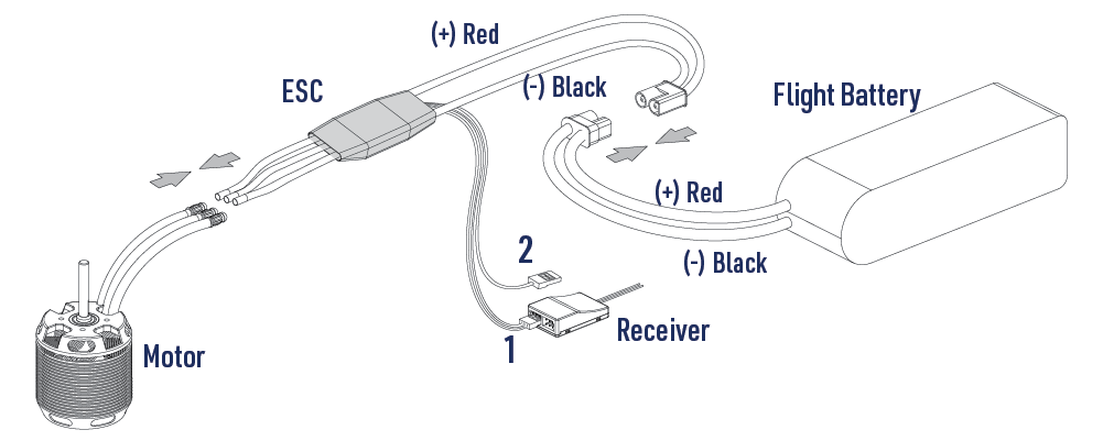
KAVAN PLUS Anschlussdiagramm
- Gaskanal Kabel (Weiss/Rot/Schwarz): Wird eingesteckt in den Gaskanal des Empfängers oder des Flugkontrollers. Das weisse Kabel überträgt das Sender Gassignal, das rote & schwarze sind die BEC Ausgangs Kabel.
- Umkehrbremsen Signal/Programmier Kabel (Gelbes Kabel):
• Wird in irgendeinen freien Kanal des Empfängers eingesteckt, wenn der Umkehrbremsen Modus genutzt wird um diesen Ein/Aus zu schalten.
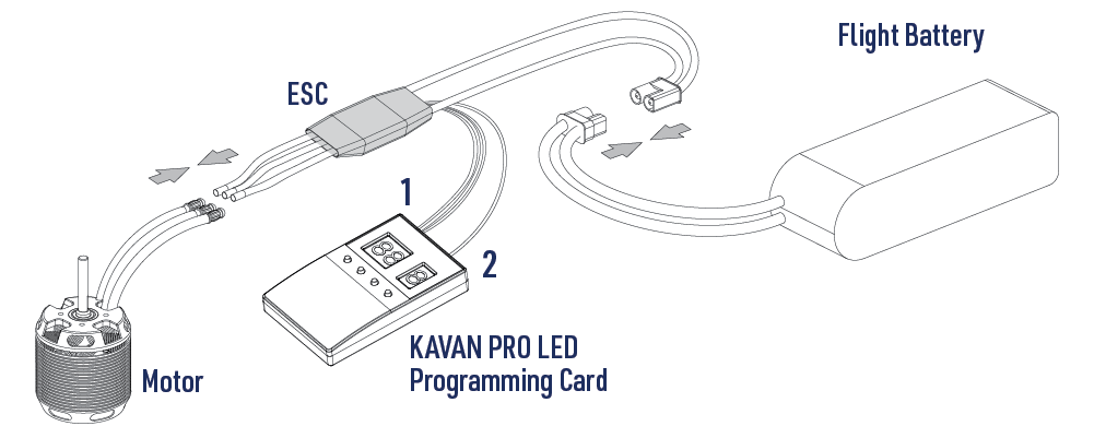
• Wird mit der LED KAVAN PRO Programmier Karte verbunden, wenn der ESC programmiert werden soll.
ESC/Sender Kalibrierung
- Schalten Sie den Sender ein und bewegen Sie den Gasknüppel in Vollgasstellung.
- Schliesen Sie die Antriebsbatterie an den Regler an. Der Motor meldet sich mit „123“ um anzuzeigen, daß der ESC angeschlossen wurde.
- Dann meldet sich der Motor mit zwei kurzen beep um die Vollgasstellung zu melden.
- Bewegen Sie den Gasknüppel innerhalb von 5 Sek. nach den zwei peep zur Leerlaufposition.
- Der Motor meldet sich dann mit einer Anzahl peep um die Anzahl der Zellen des angeschlossenen Akkus mitzuteilen.
- Der Motor meldet sich danach mit einem langen peep um anzuzeigen, daß die Kalibrierung komplett ist. Der ESC ist nun „scharf“.
Normale ESC Einschalt-Prozedur
- Sender einschalten und Vollgas geben.
- Akku an den ESC anschliessen. Der Motor meldet sich mit „123“.
- Der Motor meldet die Anzahl der Zellen des LiPo Akkus mit entsprechender Anzahl peep.
- Der Motor gibt einen langen peep aus um anzuzeigen, daß der ESC startbereit ist.
Programmierung

Gebrauch der KAVAN PRO programmier Karte
Schließen Sie das Programmierkabel (gelbes Kabel) des Reglers an den ESC auf der LED-Programmierkarte PRO an und schließen Sie das Servokabel des Reglers an die Versorgungsbuchse (+)/(-) auf der LED-Programmierkarte an.
Programmierung mit ihrem Sender
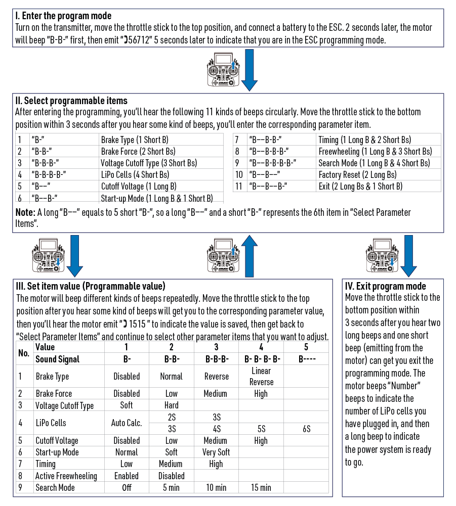
Sie erfolgt in 4 Schritten: Zugang zum Programmiermodus → Auswahl der programmierbaren Features → Einstellung der Werte → Beendigung des Programmiermodus.
Programmable functions
*) Factory default setting.
| No. | Wert | 1 | 2 | 3 | 4 | 5 |
| 1 | Bremsen Typ | *Inaktiv | Normal | Umkehr | Linear-Umkehr | |
| 2 | Bremskraft | *Niedrig | Mittel | Hoch | ||
| 3 | Spannungs Cut-off Typ | *Weich | Hart | |||
| 4 | LiPo Zellen | *Automatisch | 2S / 3S | 3S / 4S | 5S | 6S |
| 5 | Cut-off Spannung | Inaktiv | Niedrig | *Mitte | Hoch | |
| 6 | Start-up Modus | *Normal | Weich | Sehr weich | ||
| 7 | Timing | Niedrig | *Mittel | Hoch | ||
| 8 | Freilauf | *Aktiv | Inaktiv | |||
| 9 | Suchmodus | *Inaktiv | 5 min | 10 min | 15 min |
- Brake type
Normal brake: Move the throttle stick to the bottom position. The function is now activated. In this mode, the brake amount equals to the brake force you've pre-set.
Reverse brake: After selecting this option, the Reverse Brake signal wire (its signal range must be the same as the throttle range) must be plugged into any vacant channel on the receiver. You can control the motor direction via that channel. The channel range of 0–50 % is the default motor direction, the channel range of 50 % to 100 % will cause the motor to spin counterclockwise. The channel stick should be within the channel range of 0–50 % (0 would be better) when the first time you power on the ESC. After the Reverse function is activated, the motor will stop first and then spin in the reversed direction and then increase to the speed corresponding to the throttle input. Either signal loss, no matter whether reverse brake signal loss or throttle signal loss during the flight can cause the throttle signal loss protection to be activated.
Linear reverse brake: After selecting this option, the Reverse Brake signal wire must be plugged into any vacant channel on the receiver, and you can control the motor direction via that channel. This channel should be set to a proportional control (usually a knob or slider on the transmitter). Turn the proportional control to activate the reverse function. The speed of the motor is controlled by the proportional control. When reversed, the initial throttle value is started at 10 %, and the throttle stroke of the linear switch is cured to 1.34 ms – 1.79 ms. The channel stick should be at 0 % throttle position when the first time you power on the ESC. Either signal loss, no matter whether reverse brake signal loss or throttle signal loss during the flight can cause the throttle signal loss protection to be activated. - Brake force
This item is only effective in the "Normal brake" mode. The higher the level, the stronger the braking effect, where the low/medium/high corresponds to the braking force: 60 %, 90 %, 100 %. - Voltage cut-off
Soft cut-off: After selecting this option, the ESC will gradually reduce the output to 60 % of the full power in 3 seconds after the low voltage cut-off protection is activated.
Hard cut-off: After selecting this option, the ESC will immediately cut-off the output when the low voltage cut-off protection is activated. - LiPo cells
The ESC will automatically calculate the number of LiPo cells you have plugged in as per the "3.7 V/Cell" rule if "Auto Calc." is selected, or you can set this item manually. - Cut-off voltage
If set off, the low voltage protection function is disabled. In addition, the protection voltage value of the low voltage protection function corresponding to the low/medium/three modes is about 2.8 V/section, 3.0 V/section and 3.4 V/section. This value is the voltage of a single battery, multiplied by the number of lithium batteries automatically identified by the electronic governor or the number of lithium batteries manually set, which is the protection voltage value of the battery. (For example, if the low voltage protection threshold of 3 lithium batteries is medium, the protection voltage of the batteries is 3×3.0 = 9.0 V) - Start-up mode
This is used to adjust the throttle response time of ESC acceleration from 0 % to 100 %. Normal/soft/very soft correspond to approximately 200 ms/500 ms/800 ms respectively. - Timing
Can adjust the drive motor timing value. The low/medium and high are respectively: 5°/15°/25°. - Active freewheeling (DEO)
This item is adjustable between "Enabled" and "Disabled", and it is enabled by default. With it enabled, you can have better throttle linearity or smoother throttle response. - Search mode
After selecting this option, ESC will force the motor to beep for the set time when the throttle is kept at 0 %.
Troubleshooting and protection functions
| Troubles | Warning tones | Causes | Solutions |
|---|---|---|---|
| The ESC didn’t work after it was powered on while the motor kept beeping. | "BB, BB, BB,....." | The input voltage was beyond the operation g voltage range of the ESC. | Adjust the power-on voltage and ensure it’s in the operating voltage range of the ESC. |
| The ESC didn’t work after it was powered on while the motor kept beeping. | "B–, B–, B–, B–....." | The ESC didn’t receive any throttle signal from the receiver. | Check if the transmitter and receiver are well paired, or if any poor connection exists between the ESC and receiver. |
| The ESC didn’t work after it was powered on while the motor kept beeping. | "B, B, B, B....." | The throttle stick has not been moved to the bottom position. | Move the throttle stick to the bottom position and calibrate the throttle range. |
| The ESC didn’t work after the throttle calibration while the motor kept beeping. | "B, B, B, B....." | The throttle range you set was too narrow. | Re-calibrate the throttle range. |
| The ESC output suddenly reduced to 60 % during the flight, the motor kept beeping after the flight was completed but the battery was still connected to the ESC. | "BB, BB, BB....." | The ESC thermal protection has been activated. | Improve the heat-dissipating condition (i.e. add a cooling fan) or reduce the ESC load. |
| The ESC output suddenly reduced to 60 % during the flight, the motor kept beeping after the flight was completed but the battery was still connected to the ESC. | "BBB, BBB, BBB....." | The low-voltage cut-off protection has been activated. | Change another pack. Lower down the cut-off voltage or disable the LVC protection (we do not recommend this). |
- Start-up protection: The ESC will monitor the motor speed during the start-up process. When the speed stops increasing or the speed increase is not stable, the ESC will take it as a start-up failure. At that time, if the throttle amount is less than 15 %, the ESC will try to restart automatically. If it is larger than 20 %, you need to move the throttle stick back to the bottom position first and then restart the ESC. (Possible causes of this problem: poor connection/disconnection between the ESC and motor wires, propellers are blocked, etc.)
- ESC thermal protection: The ESC will gradually reduce the output but won’t cut it off when the ESC temperature goes above 120 °C. To ensure the motor can still get some power and won’t cause crashes, the maximum reduction is about 60 % of the full power. (Here we are describing the ESC’s reaction in soft cut-off mode, while if in hard cut-off mode, it will immediately cut off the power.)
- Throttle signal loss protection: When the ESC detects loss of signal for over 0.25 seconds, it will cut off the output immediately to avoid an even greater loss which may be caused by the continuous high-speed rotation of propellers or rotor blades. The ESC will resume the corresponding output after normal signals are received.
- Overload protection: The ESC will cut off the power/output or automatically restart itself when the load suddenly increases to a very high value. (A possible cause of sudden load increase is that propellers are blocked.)
- Low voltage protection: When the battery voltage is lower than the cut-off voltage set by the ESC, the ESC will trigger the low-voltage protection. If the battery voltage is set to soft cut-off, the battery voltage will be reduced to a maximum of 60 % of the full power. When set to hard cut-off, the output is cut-off immediately. After the throttle returns to 0 %, the ESC will drive the motor to sound the alarm.
- Abnormal voltage input protection: When the battery voltage is not within the input voltage range supported by the ESC, the ESC will trigger the Abnormal input voltage protection, and the ESC will drive the motor to sound the alarm.
Safety precautions
- Do not install the propeller on the motor when you test the ESC and motor for the first time to verify the correct settings on your radio. Only install your propeller after you have confirmed that the settings on your radio are correct.
- Never use ruptured or punctured battery cells.
- Never use battery packs that are known to overheat.
- Never short circuit battery or motor terminals.
- Always use proper insulation material for cable insulation.
- Always use proper cable connectors.
- Do not exceed the number of cells or servos specified for the ESC.
- Wrong battery polarity will damage the ESC and void the warranty.
- Install the ESC in a suitable location with adequate ventilation for cooling.
- Use only batteries that are supported by the ESC and ensure the correct polarity before connecting.
- Switch your transmitter ON first and ensure the throttle stick is in the minimum position before connecting the battery pack.
- Never switch your transmitter OFF while the battery is connected to your ESC.
- Only connect your battery pack just before flying and do not leave your battery pack connected after flying.
- Handle your model with extreme care once the battery pack is connected and keep away from the propeller at all times. Never stand in line or directly in front of any rotating parts.
- Do not immerse the ESC under the water, do not allow it to get wet while powered up.
- Always fly at a designated flying site and follow the rules and guidelines set by your modeller’s club.
Recycling and waste disposal note (European Union)

Electrical equipment marked with the crossed-out waste bin symbol must not be discarded in the domestic waste; it should be disposed of via the appropriate specialised disposal system. In the countries of the EU (European Union) electrical devices must not be discarded via the normal domestic waste system (WEEE - Waste of Electrical and Electronic Equipment, Directive 2012/19/EU). You can take your unwanted equipment to your nearest public collection point or recycling centre, where it will be disposed of in the proper manner at no charge to you. By disposing of your old equipment in a responsible manner you make an important contribution to the safeguarding of the environment!
EU declaration of conformity (European Union)
Hereby, KAVAN Europe s.r.o. declares that these KAVAN Line brushless electronic speed controllers are in compliance with the essential requirements as laid down in the EU directive(s) concerning electromagnetic compatibility. The full text of the EU Declaration of Conformity is available at www.kavanrc.com/doc/.
Guarantee
The KAVAN Europe s.r.o. products are covered by a guarantee that fulfils the currently valid legal requirements in your country. If you wish to make a claim under guarantee, please contact the retailer from whom you first purchased the equipment. The guarantee does not cover faults which were caused in the following ways: crashes, improper use, incorrect connection, reversed polarity, maintenance work carried out late, incorrectly or not at all, or by unauthorised personnel, use of other than genuine KAVAN Europe s.r.o. accessories, modifications or repairs which were not carried out by KAVAN Europe s.r.o. or an authorised KAVAN Europe s.r.o., accidental or deliberate damage, defects caused by normal wear and tear, operation outside the Specification, or in conjunction with equipment made by other manufacturers. Please be sure to read the appropriate information sheets in the product documentation!
