KAVAN Smart PRO GPS2 Logger - Bedienungsanleitung
Einleitung
Herzlichen Glückwunsch zum Kauf des Smart PRO GPS2 Loggers, einem Telemetriegerät, das eine schnelle und genaue Positionserkennung in Echtzeit und ein Feedback bietet. Dieser Logger verwendet mehrere Satellitennavigationssysteme, um maximale Genauigkeit und Auflösung zu erreichen. Der integrierte Speicher Flash ermöglicht eine Aufzeichnung aller Daten. Die aufgezeichneten Daten können mit der kostenlosen Software MAV Manager heruntergeladen und auf einem Computer analysiert werden.
Merkmale
- Kleine Abmessungen, hohe Messgenauigkeit
- Großer Industriespeicher für die Datenaufzeichnung
- GPS-Chip-Set der neuesten Generation, das mehrere Satellitensysteme unterstützt
- 3-Achsen-Magnetometer / Kompass für externe Navigationszwecke
- Backup-Superkondensator zum schnellen Wiederauffinden der Position nach der Abschaltung
- Messung und Aufzeichnung der Versorgungsspannung
- Automatische Telemetrie-Erkennung : FPort, Duplex EX, Hott, MSB, S.Bus2, P²Bus.
- Automatische Zeitzonenerkennung
- Konfiguration über den Sender oder das Programm MAV Manager
- Firmware-Updates
Technische Daten
- Abmessungen: 28×30×9 mm
- Gewicht: 14 g
- Speicher: 256 MB
- Unterstützte Navigationssysteme: GPS, GALILEO, GLONASS
- Aufzeichnungszeit (5 Aufzeichnungen/s): 66 Stunden
- Aufzeichnungsfrequenz: 10 Hz, 5 Hz, 2 Hz, 1 Hz
- Lebensdauer des Speichers Flash: 100 000 Überschreibzyklen
- Betriebsstrom: 50 mA
- Betriebstemperatur: (-20)–85 °C
- Versorgungsspannung: 3.5–8.4 V
- Telemetrie: FPort, Duplex EX, Multiplex MSB, Graupner Hott, Futaba S.Bus2, PowerBox P²Bus
- Status LED: JA
- GNSS Empfängerempfindlichkeit: -167 dBm
- GNSS max. Belastung: 4G
Verfügbare Telemetrie
Die Telemetrieoptionen sind abhängig vom verwendeten Funkanlagensystem. Die kompletten Daten werden automatisch im internen Speicher Flash gespeichert.
| Parameter | Beschreibung |
|---|---|
| Zeitstempel | Aktuelle genaue GPS-Zeit. |
| Breitengrad | Koordinaten Nord/Süd. |
| Längengrad | Koordinaten Ost/West. |
| Status | Anzeige von Aktivität (1 = korrekte Position) oder Fehlerzustand. |
| Satelliten | Anzahl der erkannten Satelliten. |
| Abs. Höhe | Höhe über dem Meeresspiegel. |
| Entfernung | Entfernung von der “Startposition“. |
| Geschwindigkeit | 2D/3D-Geschwindigkeit relativ zum Boden. Der Typ der Geschwindigkeitsmessung kann in der Konfiguration eingestellt werden. |
| Rel. Höhe | Höhe relativ zur “Startposition”. |
| Kurs | Flugrichtung. Die Werte liegen im Bereich 0°-359°: 0° = Norden, 90° = Osten, 180° = Süden, 270° = Westen. Ist die Geschwindigkeit gleich Null, wird der Kurs nach dem Kompass berechnet. |
| Azimuth | Die Position des Modells in Bezug auf die “Startposition“. Die Werte liegen im Bereich 0°-359°: 0° = Norden, 90° = Osten, 180° = Süden, 270° = Westen. |
| Temperatur | Interne Temperatur. |
| Magnetometer X/Y/Z | Werte des 3-Achsen-Magnetometers. Können für weitere Berechnungen verwendet werden. |
| Spannung | Empfängerspannung (nur geloggt). |
| Route | Gesamtstrecke, die während des Fluges zurückgelegt wurde (nur geloggt). |
Installation
Schließen Sie den Logger Smart PRO GPS2 an den Telemetrieport des Empfängers an. Platzieren Sie den Sensor oben am Flugzeug, so dass seine Antenne in keine Richtung abgeschirmt ist. Abschirmende Materialien wie Metall, Carbon oder andere leitende Materialien können die Fähigkeit zur korrekten Positionsbestimmung beeinträchtigen. Stellen Sie außerdem sicher, dass die Antennen des 2,4 GHz Systems mindestens 20 cm oder mehr vom GPS Logger-Sensor entfernt sind. Versuchen Sie, den Sensor nicht mechanisch zu belasten. Vermeiden Sie engen Kontakt mit wärmeerzeugenden Komponenten (wie Motoren oder Drehzahlreglern). Verwenden Sie weiches doppelseitiges Klebeband oder Klettband.
Um eine gute Leistung des integrierten Magnetometers zu gewährleisten, installieren Sie das Gerät in einem Abstand von mindestens 20 cm zu magnetisierten Objekten und Kabeln, die die Servos/Motoren versorgen. Achten Sie auf die Ausrichtung des Geräts in Bezug auf die Flugrichtung, wie in der Abbildung unten dargestellt.

Power up the receiver with the GPS Logger attached. The red LED flashes once to indicate correct initialization. After a few seconds (or minutes if the device has been unpowered for a day or more), the device reports a ”3D position fix”. From this moment on, the device can start logging depending on the condition set in the configuration. The logging is indicated by a flashing LED synchronously with the sampling rate.
Each time the logging is started, a new file is created at the internal Flash storage. The log files are named according to current date and time in the following format:
”GYYYYMMDD HHhNN.log” (where YYYY = year, MM = month, DD = day, HH = hour and NN = minute). Example: G20210605 20h47.log
It is not necessary to delete old log files manually. When there isn't enough free space, the oldest log files are deleted automatically. The internal file system is robust and immune against power failures so the battery may be disconnected anytime.
Telemetry and settings
The device is compatible with JETIBOX and HOTT SMART-BOX for programming. The JETIBOX menu is divided into three sections:
- Actual values - Displays the latest telemetry values (altitude, distance, position, temperature) including minimums and maximums.
- Reset Min/Max - Press LEFT+RIGHT buttons together to reset all minimums and maximums.
- Settings - Basic settings of the sensor.
- Language - You can choose the language of the JETIBOX screen.
- Timezone - Press Left+Right to switch between automatic timezone detection and manual configuration. If the “Auto” mode is used, the detected timezone is displayed when the sensor has a position fix. If the timezone is detected incorrectly, switch to “Manual” mode and type the zone using LEFT or RIGHT keys. For example, Central Europe uses GMT+1, while US Eastern Time uses GMT-5.
- Apply DST - Set “Yes” if you want to use Daylight Saving Time (or Summer Time) – this function will add or subtract one hour depending on your current location.
- Speed measure - Set the “2D” option if you need to use only ground speed measurements (walking, boat, and car). In the case of a flying model, use “3D” measurement type to include vertical components. This parameter influences the speed, distance and trip (route) measurements.
- GPS profile - Set the GPS profile according to supposed usage. This parameter influences the accuracy and speed/latency of position detection.
- Air 1G - flying objects that do not change direction very fast (large scale models, gliders, cinematic drones...).
- Air 2G - faster-flying objects that perform basic manoeuvres (trainers, EPP...).
- Air 4G - fast-flying objects that are capable of aerobatics (3D aerobatic models, F3A, jets). Default option.
- Walk/2D - slow motion on the ground.
- Car/2D - a mode suitable for a car.
- Log period - Set the logging period according to your preferences. The maximum value (10 Hz) stores data 10 times per second and can cover all flight details. Please note that with a higher logging rate also the size of log files grows faster.
- Logging - Set the condition that must be fulfilled to start logging:
- Auto/Fix - the logging starts automatically when the position is determined (the logger gets a 3D fix).
- Auto/10kmh - the logging starts automatically when the logger gets 3D fix and the speed exceeds 10 km/h.
- Start/Stop - the logging starts after the 3D fix and speed exceeds 10 km/h. It stops after 10 s below 5 km/h.
- Home location - If “Automatic” mode is used, the home location is determined after each startup – the position where the GPS Logger got its first position fix. The following telemetry is calculated respecting the home location: Relative altitude, distance and azimuth. In “Manual” mode the last known home location is used.
- Set home location - By pressing the Left+Right arrows you can set the current GPS coordinates as a reference point. The home location is updated if you press Left+Right arrows on the JETIBOX main telemetry screen, independently on the Auto/Manual settings.
- Minimum satellites - Set the minimum number of detected satellites before confirming the 3D position fix.*
- Startup HDOP - Set the initial required “horizontal delusion of precision” before confirming the 3D position fix. The HDOP parameter says how much we can trust the position measurement, where a lower value is better. For example, value 2.0 states that the typical deviation of current measurement from an ideal position is up to 2 meters.
- Service - In this menu, you can view the device version, and reset it to the default factory configuration.
- Memory/Free - Shows the available space at the internal Flash memory.
- Format - In case of a file system error, you may format the Flash memory. Please note that this procedure erases all the data – even configuration.
- Clear logs - Deletes all log files.
- Compass, Compass (Home) - Displays current magnetometer measurement compared to an ideal measurement, calculated based on the GPS location.
Graupner Hott Menu Structure
The GPS Logger offers telemetry as a standard GPS telemetry module.

Futaba and Multiplex connection
Futaba and Multiplex systems do not offer wireless device configuration. The telemetry transmission is possible with the following fixed sensor slots:
| Futaba S.Bus2 | Multiplex MSB | |
|---|---|---|
| Speed | 8 | 9 |
| Altitude | 9 | 10 |
| Time | 10 | - |
| Vario | 11 | - |
| Latitude | 12–13 | - |
| Longtitude | 14–15 | - |
| Distance | - | 11 |
| Satellites | - | 12 |
| Course | - | 13 |
| Note | Manual detection in the menu Linkage – Sensor. Choose F1675 GPS on slot 8. | Automatically detected by the transmitter. |
JETIBOX Connection
Plug the GPS Logger into the sensor slot of the JETIBOX. Power it up with a battery of appropriate voltage (4.5–8.4 V). Now you can configure the sensor using the arrows on the JETIBOX.


Analyze log files
The free MAV Manager software allows you to download and analyze the GPS data after the flight. You can download it from the manufacturer's website.
- Connect the MAV USB interface to the computer. Attach the GPS Logger to it.
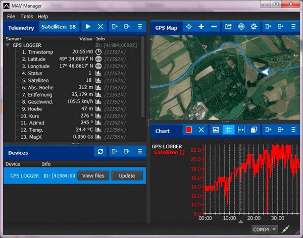
- Launch the MAV Manager and select the correct serial port at the bottom of the screen (COMxx). The GPS LOGGER will be recognized automatically.
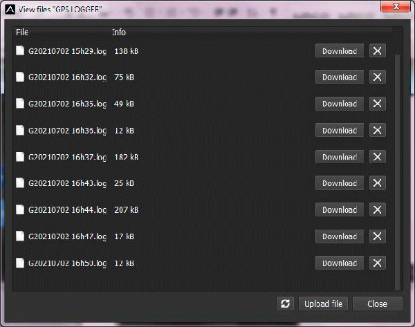
- Press “View files” in the list of devices.

- Select the log file and press the “Download” button. You will be asked to select the destination filename. When the transfer finishes, you will be asked if you want to open the downloaded file. Press “Yes”.
- You can view the logged data in a chart or map. Save the log file, or export the coordinates to KML.


Safety information
- Operate the GPS Logger always in a dry environment and within the device limits stated in this guide. Never expose the device to excessive heat or cold.
- Never apply mechanical stress or excessive force to the GPS Logger. The sensing element can measure imprecisely or be damaged if a force is applied.
- Do not remove the heat shrink tube from the device and do not try to implement any changes or modifications. This can lead to the destruction and denial of any warranty claims.
- Always check the polarity of the connection. Never inverse the polarity – this could lead to destruction.
Firmware update
Firmware updates for the GPS Logger are transferred from a PC via the USB interface. The required programs and files are available at www.mavsense.com.
Install the MAV Manager software and the USB drivers on your computer. Check the system requirements.
- Connect the USB interface to your PC, run MAV Manager - Updater and select the correct COM Port.
- Connect the GPS Logger according to the picture below.
- Select the correct *.BIN file and press the Update button.

PC configuration
It is possible to use the MAV Manager software (1.6.0 and later) to conveniently configure all device settings, display real-time telemetry and make a configuration backup. The configuration menu contains four buttons in the top toolbar:
- Refresh - forces the configuration to be reloaded from the device.
- Import - imports the settings from a file. If you have several devices and want all of them with identical settings, import the same settings to each device.
- Export - exports the settings from the device to a file. You can easily create a backup configuration stored on your PC. After making the backup, you may easily experiment with the settings and later revert to the original configuration by pressing the “Import” button and choosing the original exported file.
- Reset default - resets the device to factory defaults and reloads all the settings.

Connect the GPS Logger to your PC using the USB interface. The device will be automatically detected by the MAV Manager. The device properties are available after pressing the “Configure” button.


Real-time telemetry with min/max values. The MAV Manager can also create a log file from the real-time telemetry data, which can be viewed, analyzed, imported and exported.
GPS Logger settings. Every time you make any change in the configuration, the new value is immediately transferred to the device and saved to memory. There is no need for additional confirmation.
You can modify the telemetry settings or clear log files from the internal Flash.
Conclusion
Manufacturer
KAVAN Smart PRO GPS2 Logger is made in Czechia by MAV Sense s.r.o.
E-mail: info@mavsense.com | Web: www.mavsense.com
Recycling and waste disposal note (European Union)

Electrical equipment marked with the crossed-out waste bin symbol must not be discarded in the domestic waste; it should be disposed of via the appropriate specialised disposal system. In the countries of the EU (European Union) electrical devices must not be discarded via the normal domestic waste system (WEEE - Waste of Electrical and Electronic Equipment, Directive 2012/19/EU). You can take your unwanted equipment to your nearest public collection point or recycling centre, where it will be disposed of in the proper manner at no charge to you. By disposing of your old equipment in a responsible manner you make an important contribution to the safeguarding of the environment.
EU declaration of conformity (European Union)

Hereby, KAVAN Europe s.r.o. declares that the KAVAN Smart PRO GPS2 Logger is in compliance with the essential requirements as laid down in the EU directive(s) concerning electromagnetic compatibility. The full text of the EU Declaration of Conformity is available at www.kavanrc.com/doc.
Guarantee
The KAVAN Europe s.r.o. products are covered by a guarantee that fulfils the currently valid legal requirements in your country. If you wish to make a claim under guarantee, please contact the retailer from whom you first purchased the equipment. The guarantee does not cover faults which were caused in the following ways: crashes, improper use, incorrect connection, reversed polarity, maintenance work carried out late, incorrectly or not at all, or by unauthorised personnel, use of other than genuine KAVAN Europe s.r.o. accessories, modifications or repairs which were not carried out by KAVAN Europe s.r.o. or an authorised KAVAN Europe s.r.o., accidental or deliberate damage, defects caused by normal wear and tear, operation outside the Specification, or in conjunction with equipment made by other manufacturers. Please be sure to read the appropriate information sheets in the product documentation.