KAVAN GRE-18 Crawler Kit - Instruction manual
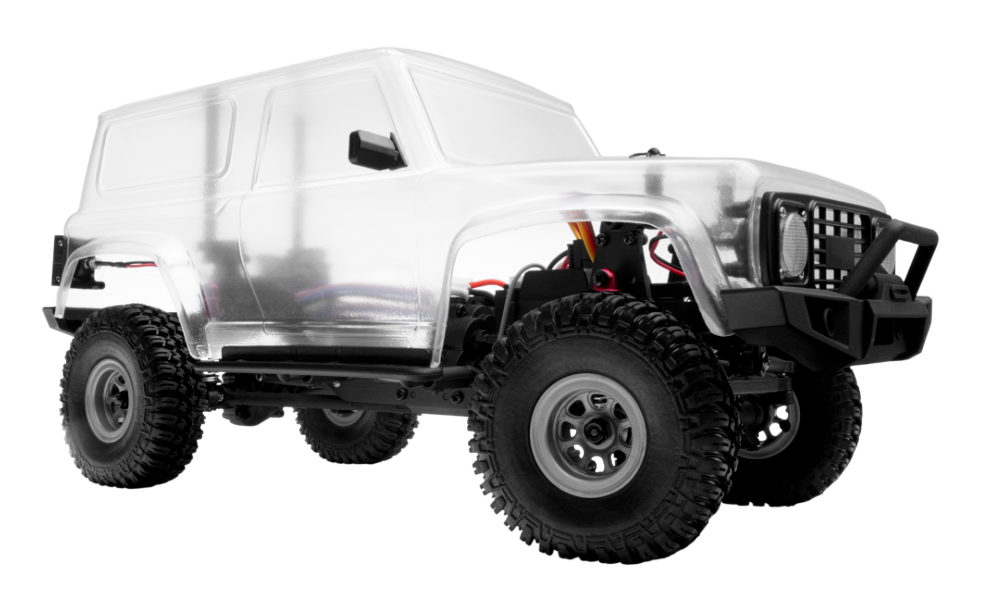
GRE-18 Kit
Introduction
The KAVAN GRE-18K is a four-wheel-drive crawler kit in 1:18 scale. The box includes the mechanical parts, radio system and onboard electronics. Assemble and paint the model before preparing it for operation.
Technical specifications
| Scale | 1:18 |
|---|---|
| Drive | 4WD crawler |
| Drive/receiver supply | 7.4 V (2S LiPo) |
| Transmitter supply | 4× AAA alkaline (1.5 V) or NiMH (1.2 V) |
| Modulation | FHSS |
| Frequency range | 2.405–2.478 GHz |
| Transmitter RF power | <20 dBm |
| Minimum transmitter/receiver separation | 40 cm |
| Battery charging temperature | 0–45 °C |
Warnings
- This is not a toy! Independent operation is intended for users older than 15 years. Younger users require proper adult supervision.
- Failure to operate or maintain this vehicle safely can result in bodily harm.
- Replace damaged components with original factory parts only. Pay special attention to the polarity of all vehicle wiring.
- Only use approved two-cell (2S, 7.4 V) lithium polymer batteries. Do not overcharge or overdischarge the battery as doing so may cause the battery to become a fire hazard. If the battery should become hot during charging, discontinue charging immediately and disconnect the battery from the charger. Never leave the battery unattended while charging. If you are unsure of how to charge this battery, please seek the advice of experienced RC users. Never let children charge the battery without adult supervision.
- The motor will become hot during use. Allow 10–15 minutes between runs for the vehicle to cool down. Doing so will prolong the life of your vehicle.
- Use common sense when selecting the environment to operate your vehicle. Do not run it in the streets, car parks or anywhere you can run into a full-size car, people or animals. Do not operate near power cables, cellular/radio towers, deep water or unstable terrain. The operator is solely responsible for their actions.
- The product is composed of precision electrical components. It is critical to keep the product away from moisture and other contaminants. If exposed to a humid environment, make sure the electronics are fully dried before using them again.
- Always check the radio range of the vehicle before operation to prevent damage to your model due to radio loss or interference.
- Operate this product to your ability. If the vehicle is dangerous to retrieve from a place, do not risk injury to retrieve it.
- Always turn on the transmitter before connecting the battery to the model. When turning off the model, turn off the receiver switch and then always disconnect the battery; only then turn off the transmitter. If this order is reversed, the model may become out of control and cause serious damage.
- Never allow transmitter batteries to run low as it may cause loss of vehicle control.
- Plastics on the vehicle are flammable and susceptible to damage or deformation due to extreme heat and cold climates. Do not store the model near any source of heat such as an oven or heater. Store the model indoors, in a dry, room-temperature environment.
- Never shorten the receiver antenna; this may affect the operational range of your radio system.
Main section
Before assembly
Sort the labelled hardware bags and compare the components with the drawings. Work in the order below. Use the screws and components shown for each step; the original plates retain the detailed part placement.
Build the chassis and install the gearbox
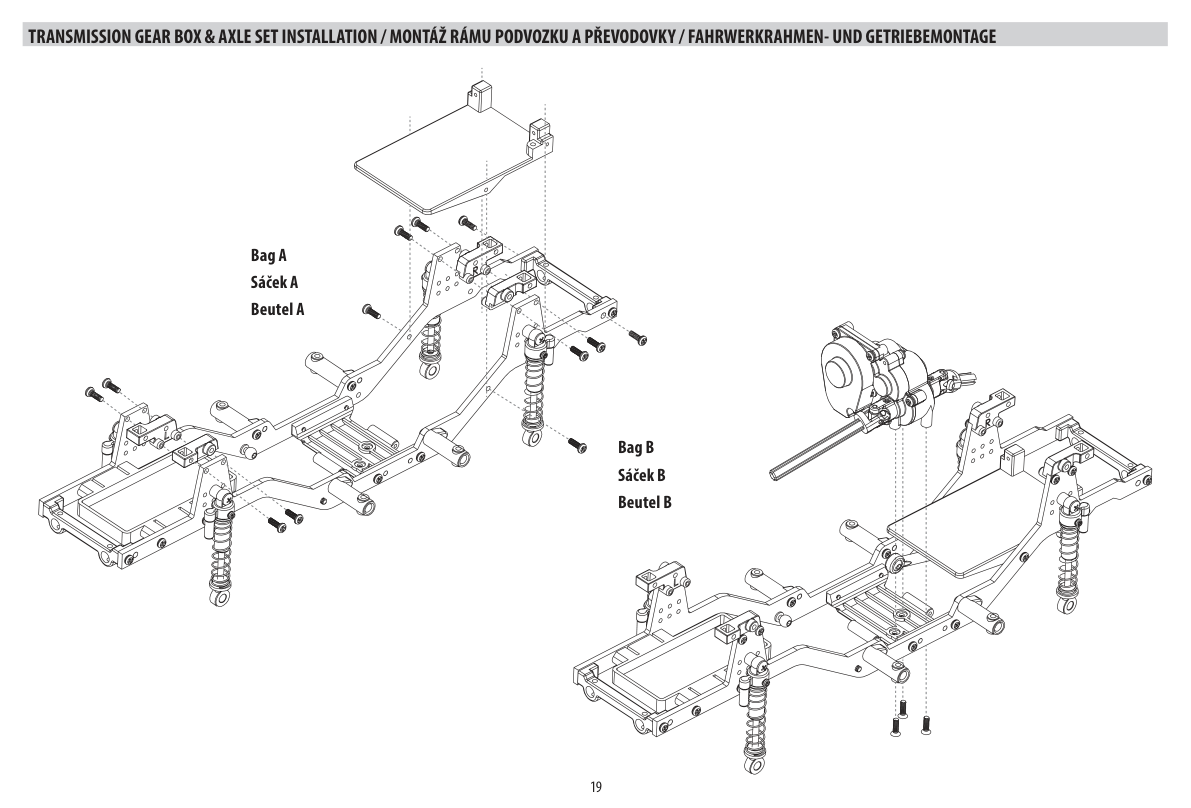
- Use bags A and B. Assemble the frame, cross-members and shock mounts in the illustrated orientation, then mount the motor/gearbox assembly. Check that the drivetrain turns freely before continuing.
Install the axle and suspension linkages
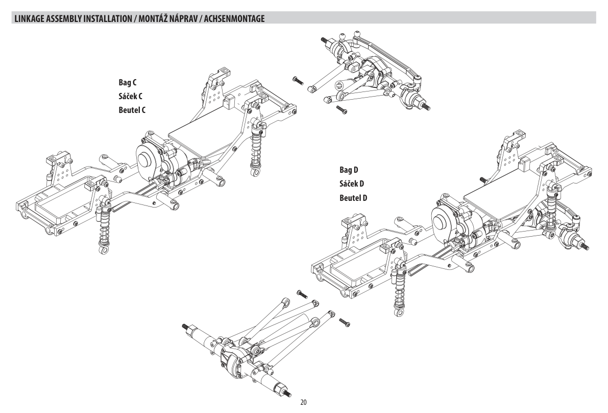
- Use bags C and D. Fit the front and rear axle assemblies, suspension links, drive shafts and lower shock ends in the drawing sequence. Check free suspension movement and secure all fasteners.
Install the electronics
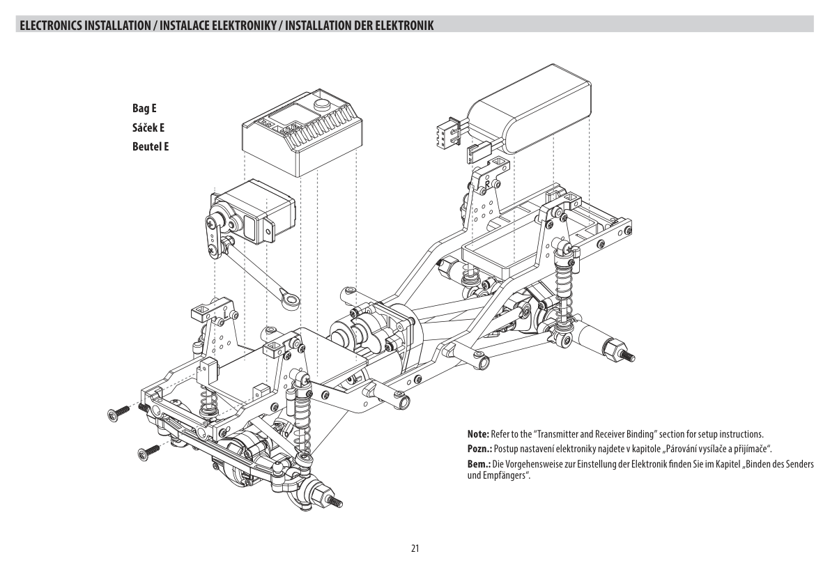
- Use bag E. Mount the steering servo and receiver/ESC in the shown positions. Centre the servo before fixing its horn. Follow Transmitter and receiver binding and the Car electronics diagram. Keep the motor disconnected during radio setup and the drive battery disconnected during wiring.
Fit bumpers and side steps
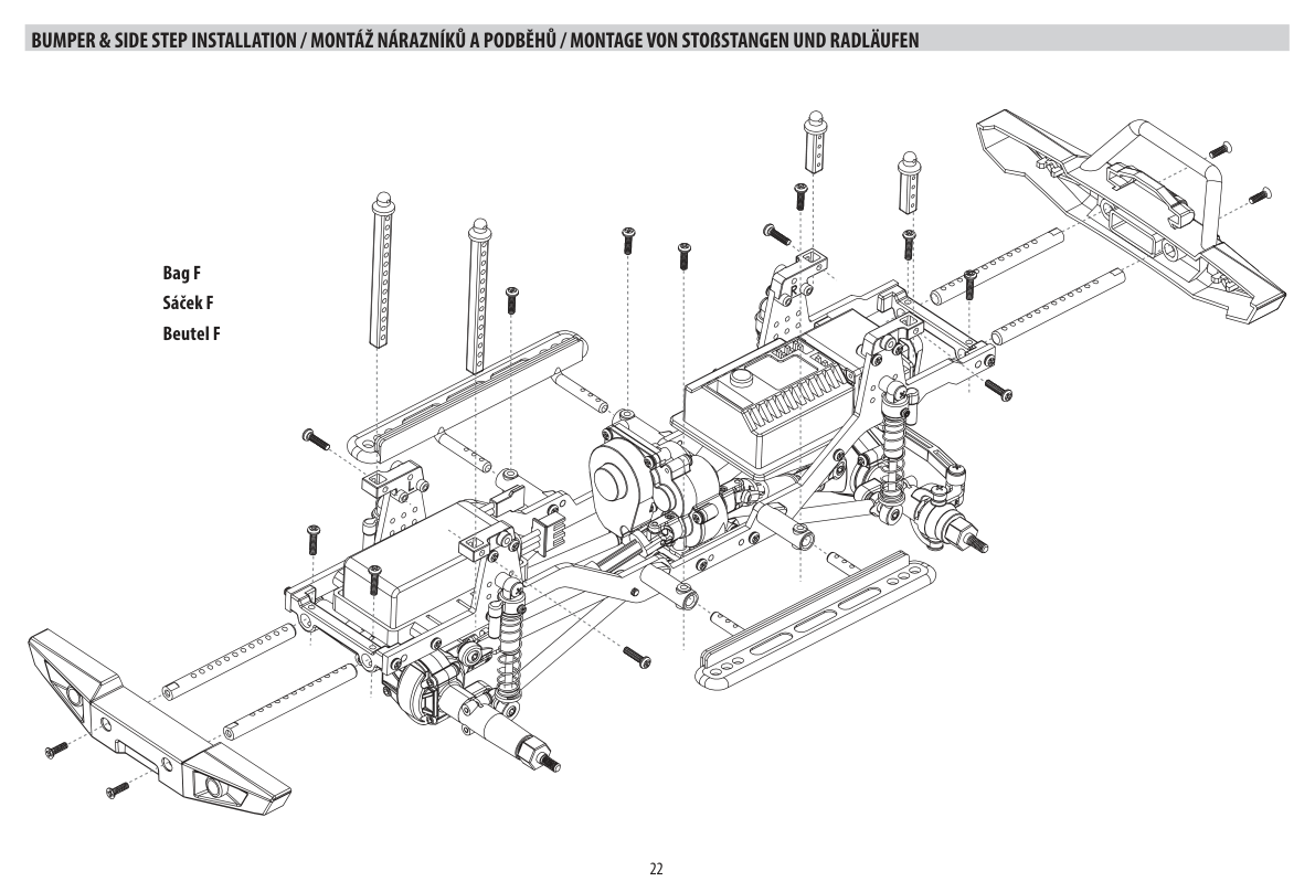
- Use bag F. Fit the front and rear bumper assemblies and side steps as illustrated. Check their orientation before tightening.
Install the wheels
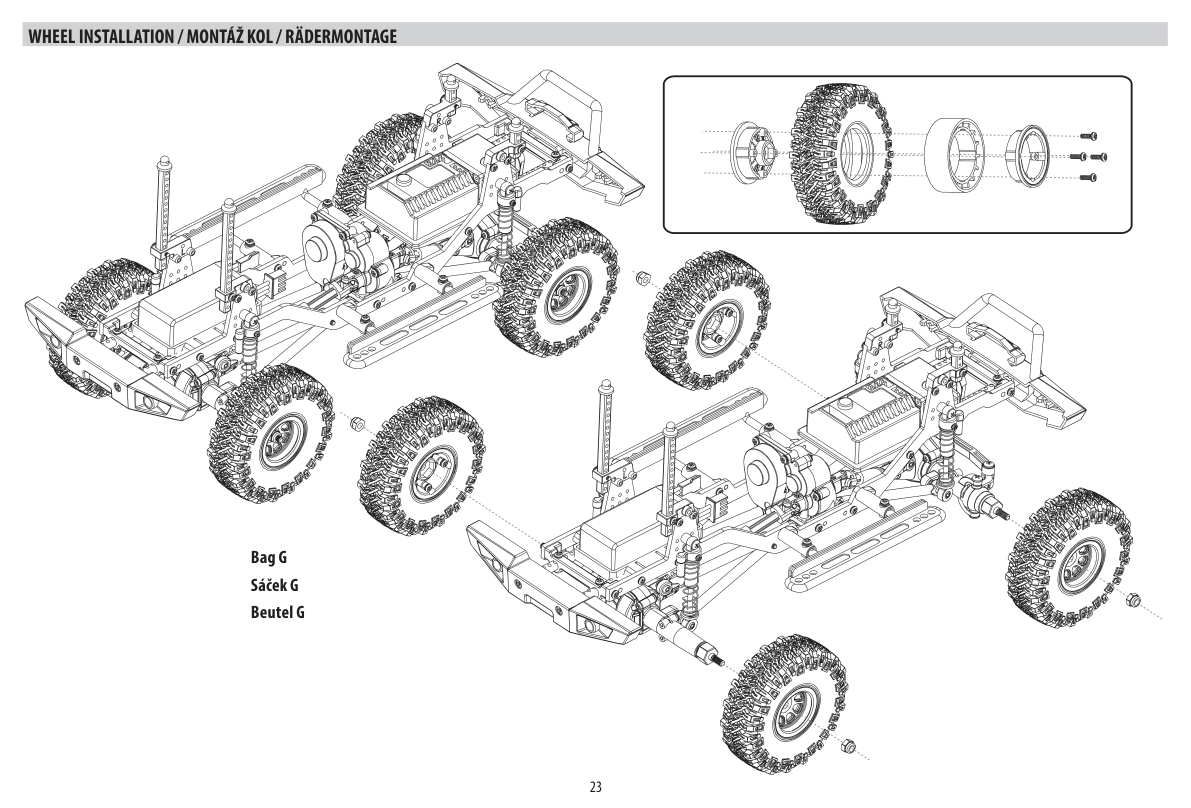
- Use bag G. Assemble the multi-piece beadlock wheels around the tyres as shown in the inset. Install the wheel-drive parts and wheels in the illustrated order, then tighten the retaining nuts. Check that every wheel rotates freely
Paint the body
Use paint specifically suitable for polycarbonate. Follow its ventilation, handling and drying instructions. Do not paint the outside or remove the exterior protective film before painting.
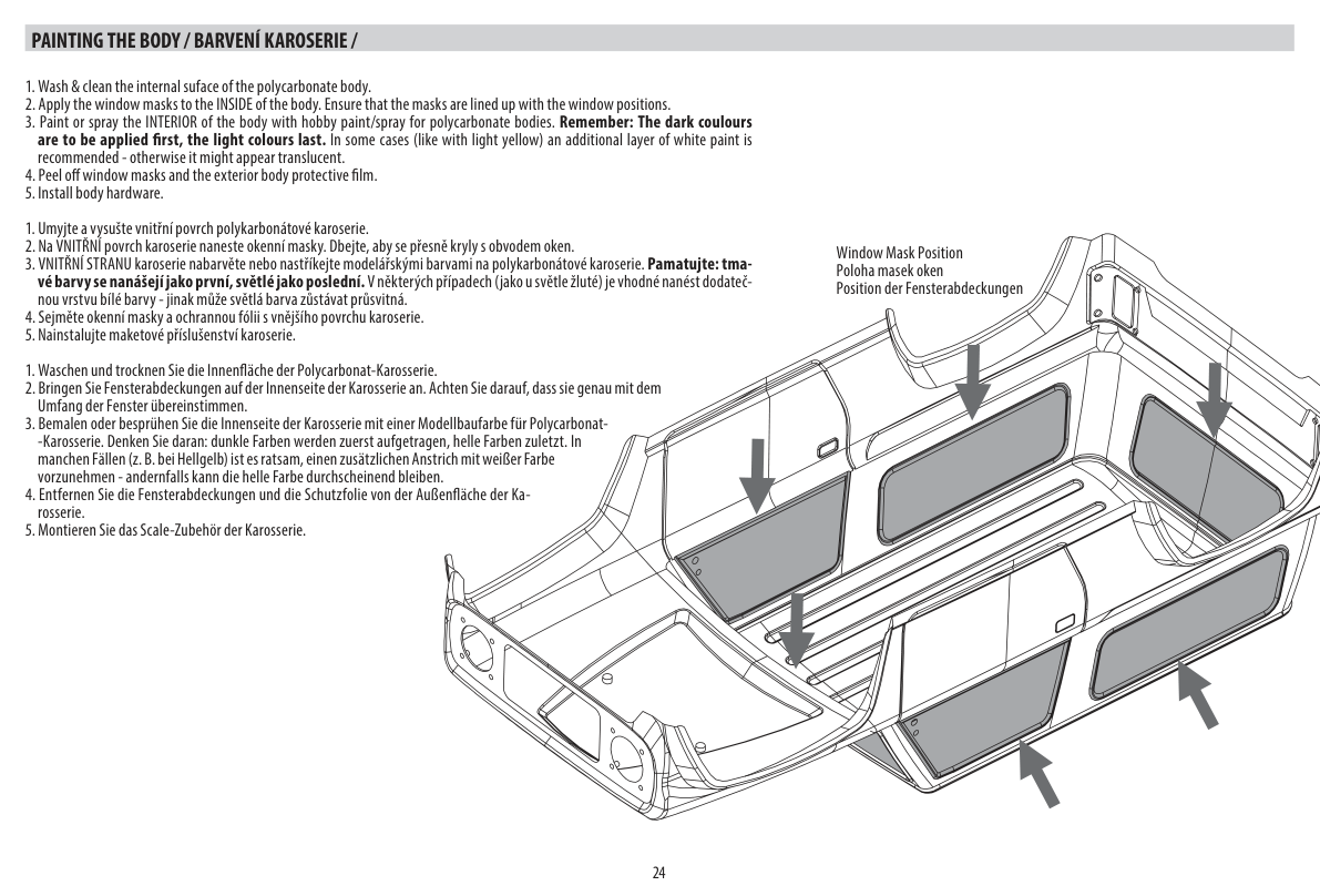
- Wash and dry the inside of the polycarbonate body.
- Apply the window masks to the inside, precisely aligned with the window edges. (Fig. 6)
- Paint the inside with paint intended for polycarbonate bodies. Apply dark colours first and light colours last. A white backing coat can make pale colours such as light yellow opaque.
- After the paint has dried, remove the window masks and the exterior protective film.
- Install the scale body accessories as described in the next step.
Assemble and fit the body
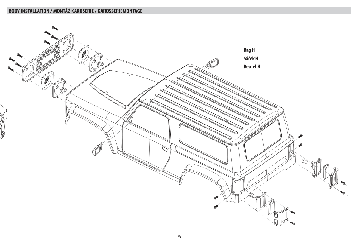
- Use bag H. Install the grille, headlight housings, mirrors, rear details and body-mount parts as illustrated. Check the body fit, leaving it accessible for the lighting installation below.
Install the lights
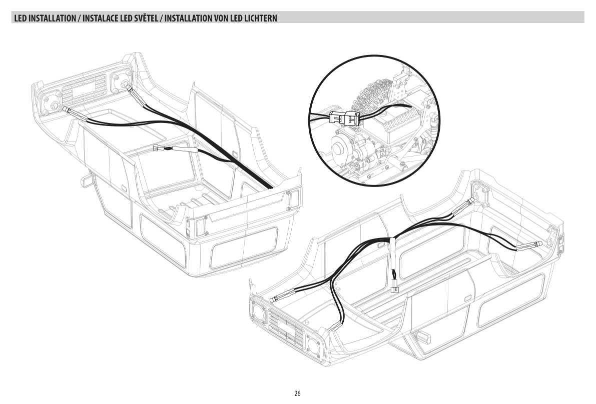
- Install the front and rear LEDs and route their leads along the inside of the body as shown. Join the matching lighting connectors shown in the detail view, keeping wires clear of the driveshafts, steering and suspension. Check the lights, then fit and secure the body without trapping wires.
Charging the battery
Before you start, get four fresh AAA alkaline batteries or fully charged NiMH batteries (not supplied in the kit) for your transmitter and charge the LiPo power pack supplied with your model using the USB charger.
- Connect the charger to a USB port then connect your battery to the charger.
- When charging, the status LED is red. Once fully charged, the status LED turns green.
- Do not leave the battery unattended when charging!
- If the battery or charger is hot, disconnect the battery and charger immediately as this may be caused by an internal short-circuit.
Lithium polymer battery safety
- Never charge a lithium polymer battery with a charger designed for NiCd, NiMH, or any other type of battery than LiPo. Use ONLY a charger designed for LiPo batteries.
- Do not leave the LiPo battery unattended during charging.
- Do not overcharge the battery.
- Always charge LiPo batteries placed on non-flammable, heat-resistant surfaces.
- Use of a LiPo-safe bag or container while charging is strongly recommended. Do not allow LiPo cells to overheat at any time. Cells heated above 60 °C are likely to be damaged and present a fire risk.
- Do not charge the LiPo pack while it is still in the model. Never charge or store battery packs in a vehicle.
- Do not over-discharge LiPo; doing so will damage the battery.
- Do not expose LiPo cells to water or moisture at any time.
- Do not store battery near open flame or heater.
- Do not assemble LiPo cells or pre-assembled packs together with other LiPo cells or packs.
- Always store LiPo batteries in a secure location away from children.
- Always remove the LiPo battery if the model is involved in any kind of crash.
- Carefully inspect the battery and connectors for even the smallest damage.
- Do not allow the electrolyte to get into the eyes or on the skin. Wash affected areas immediately if they come into contact with electrolytes. Do not alter or modify the connectors or wires of a LiPo battery pack.
- Always inspect the condition of the battery before charging and operating.
- Do not short-circuit the LiPo battery.
- Avoid direct contact with a leaky/damaged battery.
- Do not charge the battery out of the recommended temperature range (0–45 °C).
Cells may become hot after usage. Allow the pack to cool to room temperature before recharging.
Transmitter controls
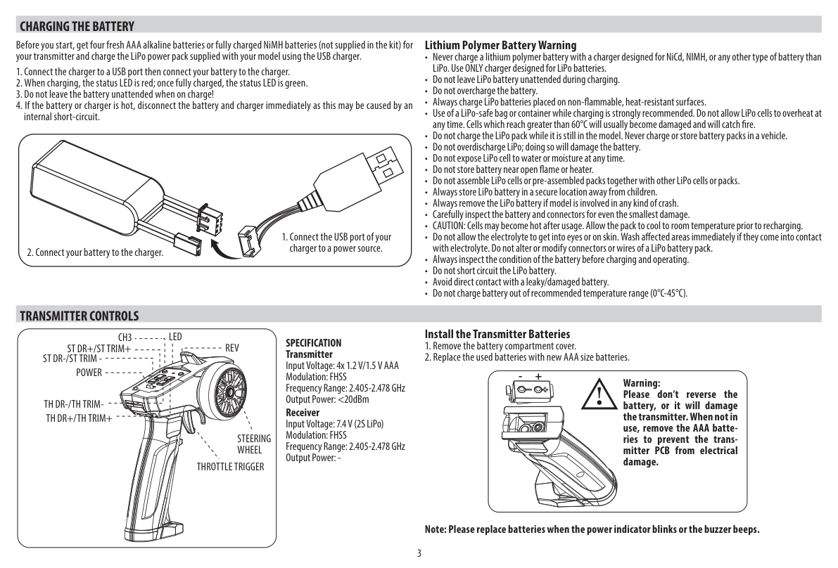
Install the transmitter batteries
- Remove the battery compartment cover.
- Fit four fresh AAA alkaline batteries or fully charged AAA NiMH batteries, observing the marked polarity, and replace the cover.
Please replace batteries when the power indicator blinks or the buzzer beeps.
Specification
Transmitter
- Supply voltage: 4× AAA, 1.2 V NiMH or 1.5 V alkaline
- Modulation: FHSS
- Frequency range: 2.405–2.478 GHz
- RF power: <20 dBm
Receiver
- Supply voltage: 7.4 V (2S LiPo)
- Modulation: FHSS
- Frequency range: 2.405–2.478 GHz
- RF power: not specified
Observe the correct battery polarity to prevent transmitter damage. Remove the AAA batteries before storing the transmitter for a prolonged period.
Transmitter and receiver binding
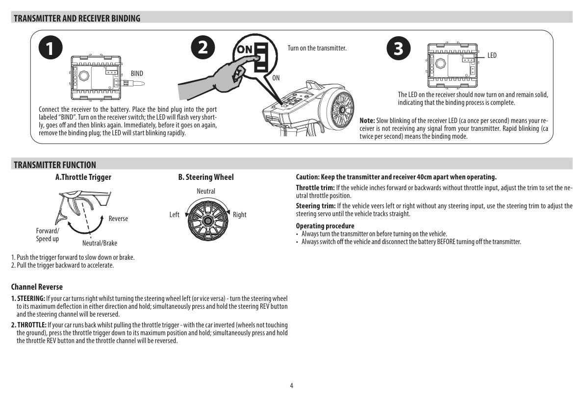
Keep the vehicle supported with its wheels clear of the ground. The receiver-first order below applies only to binding; for normal driving, switch the transmitter on first.
- Connect the receiver to the battery. Place the bind plug into the port labelled „BIND“. Turn on the receiver switch. The LED will flash very shortly, go off and then blink again. Immediately before it goes on again, remove the binding plug. The LED will start blinking rapidly.
- Turn on the transmitter.
- The LED on the receiver should now turn on and remain solid, indicating that the binding process is complete.
Slow receiver LED flashing (about once per second) indicates no transmitter signal. Rapid flashing (about twice per second) indicates binding mode.
Transmitter function
- Push the trigger forward to slow down or brake.
- Pull the trigger towards you to accelerate forwards.
The drawing identifies neutral/brake at the centre and reverse on the forward-push side of the trigger. Check the response with the wheels clear of the ground before driving.
Keep the transmitter and receiver at least 40 cm apart when operating.
Throttle trim: If the vehicle moves forwards or backwards with the trigger at neutral, press TH TRIM + or TH TRIM − until it stops.
Steering trim: If the vehicle turns with the steering wheel centred, press ST TRIM + or ST TRIM − until it travels straight.
Operating procedure
- Always turn the transmitter on before turning on the vehicle.
- Always switch off the vehicle and disconnect the battery BEFORE turning off the transmitter.
Channel reverse
- Steering: if your car turns right while turning the steering wheel left (or vice versa); turn the steering wheel to its maximum deflection in either direction and hold; simultaneously press and hold the REV button and the steering channel will be reversed.
- Throttle: if your car reverses when you pull the throttle trigger, support the car with its wheels clear of the ground, pull the throttle trigger fully towards you and hold it there; simultaneously press and hold the REV button and the throttle channel will be reversed.
Control rate
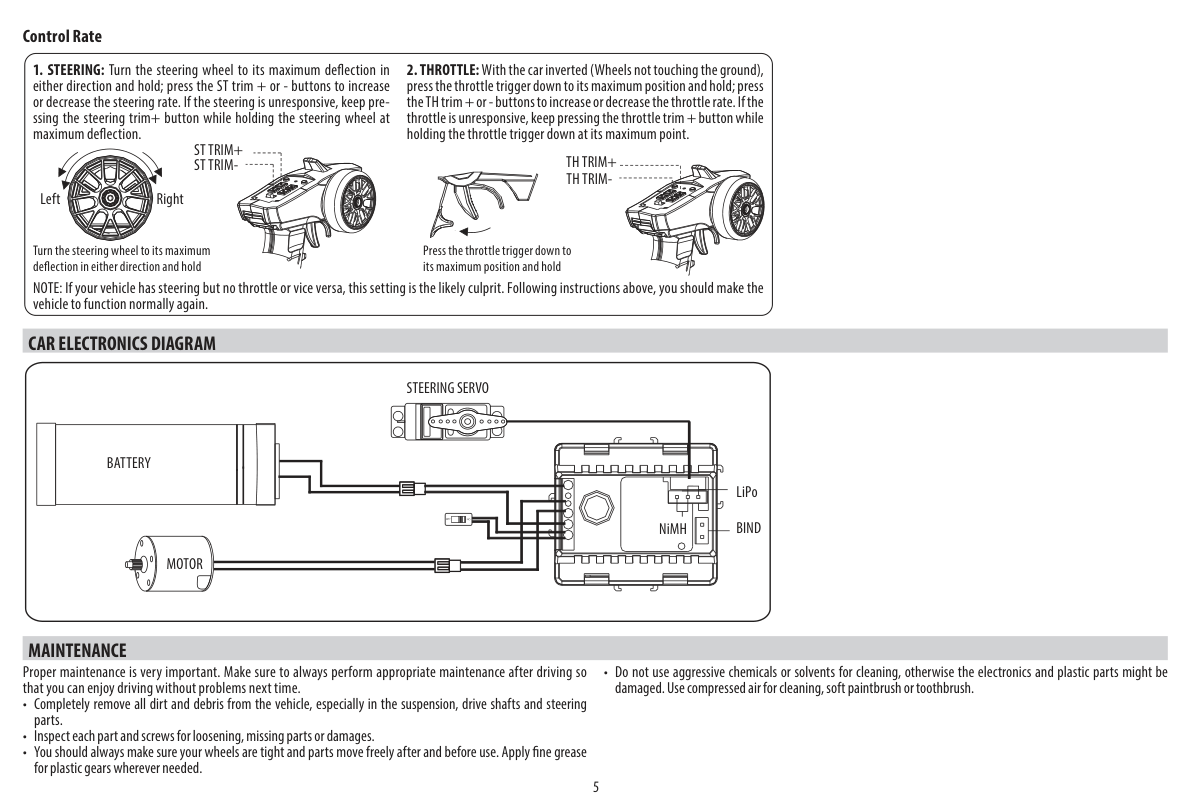
- Steering: turn the steering wheel to its maximum deflection in either direction and hold; press the ST TRIM + or ST TRIM − buttons to increase or decrease the steering rate. If the steering is unresponsive, keep pressing the ST TRIM + button while holding the steering wheel at maximum deflection.
- Throttle: support the car with its wheels clear of the ground, pull the throttle trigger fully towards you and hold it there; press the TH TRIM + or TH TRIM − buttons to increase or decrease the throttle rate. If the throttle is unresponsive, keep pressing the TH TRIM + button while holding the throttle trigger fully pulled towards you.
If steering responds but throttle does not, or vice versa, the rate setting may be the cause. Check and adjust it as described above.
Car electronics diagram
Keep the battery disconnected while changing wiring. Check the marked polarity and battery-type setting. Use the LiPo setting with the supplied LiPo pack.
Maintenance
Disconnect the drive battery before maintenance.
Proper maintenance is very important. Make sure to always perform appropriate maintenance after driving so that you can enjoy driving without problems next time.
-
Completely remove all dirt and debris from the vehicle, especially in the suspension, drive shafts and steering parts.
-
Inspect each part and screw for loosening, missing parts or damages.
-
You should always make sure your wheels are tight and parts move freely after and before use. Apply fine grease for plastic gears wherever needed.
-
Do not use aggressive chemicals or solvents for cleaning, otherwise the electronics and plastic parts might be damaged. Use compressed air for cleaning, a soft paintbrush or toothbrush.
-
Protect the electronics against extreme temperatures, moisture, dust, impacts and prolonged direct sunlight.
-
Motors, servos and gears are subject to normal wear and may need replacement during the life of the model.
Appendix
Original drawings and spare parts
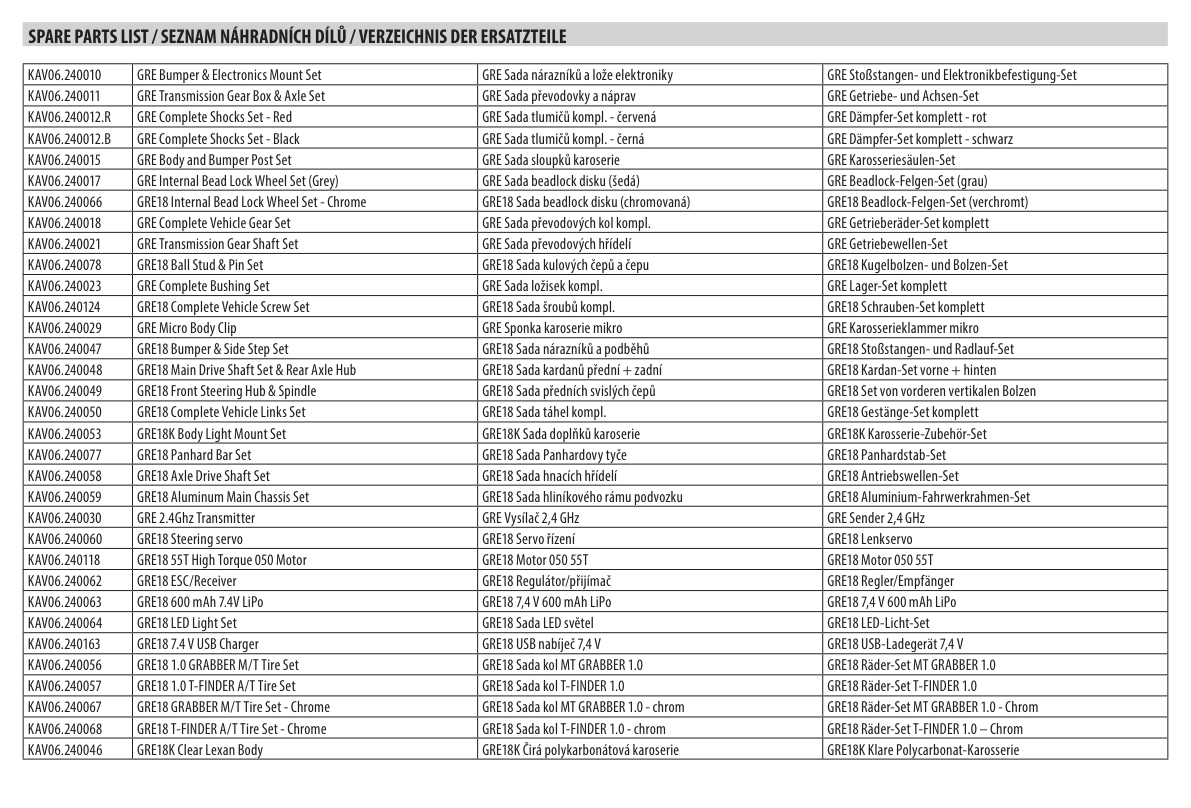
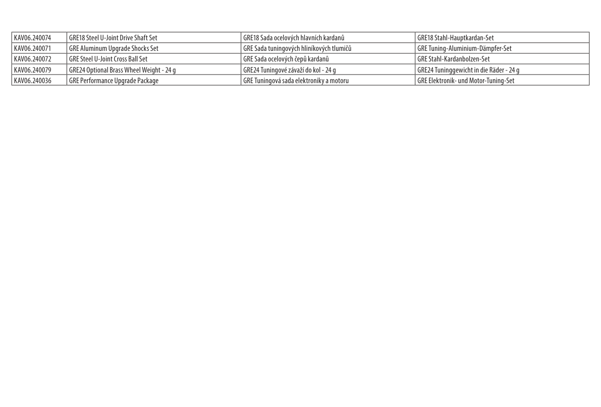
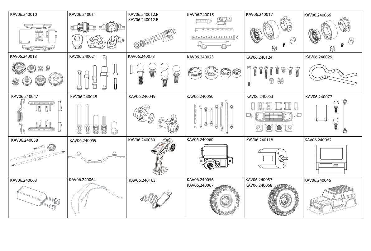
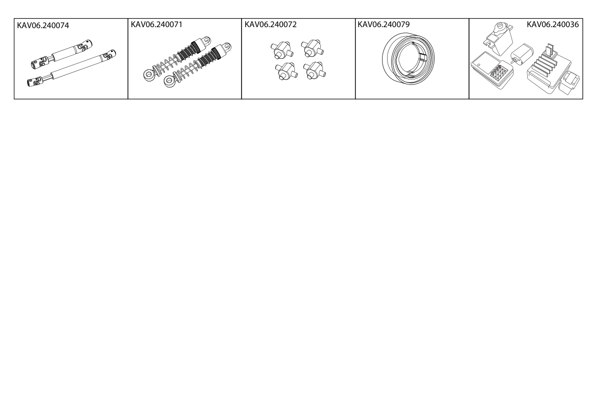
Spare parts key
| Part code | Description |
|---|---|
| KAV06.240010 | GRE Bumper & Electronics Mount Set |
| KAV06.240011 | GRE Transmission Gear Box & Axle Set |
| KAV06.240012.R | GRE Complete Shocks Set – Red |
| KAV06.240012.B | GRE Complete Shocks Set – Black |
| KAV06.240015 | GRE Body and Bumper Post Set |
| KAV06.240017 | GRE Internal Bead Lock Wheel Set (Grey) |
| KAV06.240066 | GRE18 Internal Bead Lock Wheel Set – Chrome |
| KAV06.240018 | GRE Complete Vehicle Gear Set |
| KAV06.240021 | GRE Transmission Gear Shaft Set |
| KAV06.240078 | GRE18 Ball Stud & Pin Set |
| KAV06.240023 | GRE Complete Bushing Set |
| KAV06.240124 | GRE18 Complete Vehicle Screw Set |
| KAV06.240029 | GRE Micro Body Clip |
| KAV06.240047 | GRE18 Bumper & Side Step Set |
| KAV06.240048 | GRE18 Main Drive Shaft Set & Rear Axle Hub |
| KAV06.240049 | GRE18 Front Steering Hub & Spindle |
| KAV06.240050 | GRE18 Complete Vehicle Links Set |
| KAV06.240053 | GRE18K Body Light Mount Set |
| KAV06.240077 | GRE18 Panhard Bar Set |
| KAV06.240058 | GRE18 Axle Drive Shaft Set |
| KAV06.240059 | GRE18 Aluminum Main Chassis Set |
| KAV06.240030 | GRE 2.4 GHz Transmitter |
| KAV06.240060 | GRE18 steering servo |
| KAV06.240118 | GRE18 55T High Torque 050 Motor |
| KAV06.240062 | GRE18 ESC/Receiver |
| KAV06.240063 | GRE18 600 mAh 7.4 V LiPo |
| KAV06.240064 | GRE18 LED Light Set |
| KAV06.240163 | GRE18 7.4 V USB Charger |
| KAV06.240056 | GRE18 1.0 GRABBER M/T Tire Set |
| KAV06.240057 | GRE18 1.0 T-FINDER A/T Tire Set |
| KAV06.240067 | GRE18 GRABBER M/T Tire Set – Chrome |
| KAV06.240068 | GRE18 T-FINDER A/T Tire Set – Chrome |
| KAV06.240046 | GRE18K Clear Lexan Body |
| KAV06.240074 | GRE18 Steel U-Joint Drive Shaft Set |
| KAV06.240071 | GRE Aluminum Upgrade Shocks Set |
| KAV06.240072 | GRE Steel U-Joint Cross Ball Set |
| KAV06.240079 | GRE24 Optional Brass Wheel Weight – 24 g |
| KAV06.240036 | GRE Performance Upgrade Package |
Recycling and waste disposal note (European Union)
Electrical equipment marked with the crossed-out waste bin symbol must not be discarded in the domestic waste; it should be disposed of via the appropriate specialised disposal system. In the countries of the EU (European Union) electrical devices must not be discarded via the normal domestic waste system (WEEE - Waste of Electrical and Electronic Equipment, Directive 2012/19/EU). You can take your unwanted equipment to your nearest public collection point or recycling centre, where it will be disposed of in the proper manner at no charge to you. By disposing of your old equipment in a responsible manner you make an important contribution to the safeguarding of the environment.
EU declaration of conformity (European Union)
Hereby, KAVAN Europe s.r.o. declares that the equipment KAVAN GRE-18 model car with an RC kit is in compliance with Directive 2014/53/EU. The full text of the EU Declaration of Conformity is available at www.kavanrc.com/doc.
Guarantee
The KAVAN Europe s.r.o. products are covered by a guarantee that fulfils the currently valid legal requirements in your country. If you wish to make a claim under guarantee, please contact the retailer from whom you first purchased the equipment. The guarantee does not cover faults which were caused in the following ways: crashes, improper use, incorrect connection, reversed polarity, maintenance work carried out late, incorrectly or not at all, or by unauthorised personnel, use of other than genuine KAVAN Europe s.r.o. accessories, modifications or repairs which were not carried out by KAVAN Europe s.r.o. or an authorised service centre, accidental or deliberate damage, defects caused by normal wear and tear, operation outside the Specification, or in conjunction with equipment made by other manufacturers. Please be sure to read the appropriate information sheets in the product documentation.