KAVAN Sling Mini 616mm - Instruction manual
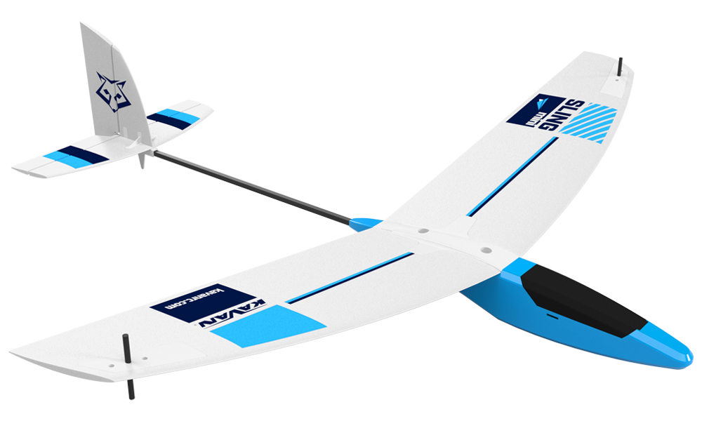
KAVAN Sling Mini
Introduction
The Sling Mini is a discus launch glider (DLG) made from composite materials and EPO foam. The factory-assembled model has elevator and rudder control, two installed servos and a receiver decoder. Fit a compatible receiver and complete the short assembly before flying.
Before you start
- If you are not an experienced RC pilot, plan to have a fully competent pilot check your completed model and help you with your first flights. Even though we have tried to provide you with a thorough instruction manual, RC models are rather complicated and an experienced modeller can quickly check over your model to make sure your first flights are successful.
- Please assemble your model exactly according to these instructions. Do not attempt to modify or change your model in any way, as doing so may adversely change its flying characteristics.
- Before you begin, please check the entire contents of this kit to make sure that no parts are missing or damaged. This will also help you to become familiar with each component of your plane. If you find that any of the parts are either missing or damaged, please contact your dealer immediately for replacement.
- Trial fit each part before glueing it in place. Make sure you are using the correct part and that it fits well before assembling. No amount of glue can make up for a poorly-fitting part.
- The manual shows the initial centre of gravity (CG) and recommended control throws. Use the specified CG for the first flight; otherwise the model may be unstable, difficult to control or unable to fly safely. See the pre-flight section before making any later adjustment.
Your dealer cannot accept kits for return if construction has begun.
Safety precautions
This RC model is not a toy. Use it with care and strictly following the instructions in this manual.
Assemble this model following strictly these instructions. DO NOT modify or alter the model. Failure to do so, the warranty will lapse automatically. Follow the instructions to obtain a safe and solid model at the end of the assembly.
Children under the age of 14 must operate the model under the supervision of an adult.
Assure that the model is in perfect condition before every flight, taking care that all the equipment works correctly and that the model is undamaged in its structure.
Fly only on days with a light breeze and in a safe place away from any obstacles.
General warnings
- An RC aeroplane can cause serious injury and damage if misused. Fly outdoors in a safe area, following this manual. Never fly over or close to people or animals.
- As the user of this product, you are solely responsible for operating it in a manner that does not endanger yourself and others or result in damage to the product or the property of others. This model is controlled by a radio signal that is subject to interference from many sources outside your control. Interference, equipment failure or pilot error can cause loss of control, so it is advisable to always keep a safe distance in all directions around your model, as this margin will help to avoid collisions or injury.
- Never operate your model with low transmitter batteries.
- Always operate your model in an open area away from power lines, cars, traffic or people. Avoid operating your model in populated areas where injury or damage can occur.
- Carefully follow the directions and warnings for this and any optional support equipment (chargers, rechargeable batteries, etc.) which you use.
- Keep all chemicals, small parts and anything electrical out of the reach of children.
- Moisture causes damage to electronics. Avoid water exposure to all equipment not specifically designed and protected for this purpose.
- The model is mostly made of plastics – it is not fireproof. Keep it away from heat sources, direct sunlight and hot enclosed cars; high temperatures can distort the foam airframe or cause other damage.
- Disconnect the receiver battery whenever the model is not in use. Keep the model and its small parts away from young children; parts could be swallowed or inhaled.
Features
- 99 % factory-assembled model requiring receiver installation and short final assembly
- Elevator and rudder control
- Stable handling, durable construction and low weight
- Two installed 1.3g servos with an S.BUS decoder
- Compatible with S.BUS receiver outputs
- Lightweight LiPo receiver battery and USB charger included
Technical specifications
| Parameter | Value |
|---|---|
| Wingspan | 616 mm |
| Length | 574 mm |
| Wing area | 5.8 dm² |
| All-up weight | 85–95 g |
| Receiver battery | 1S LiPo, 3.7 V, 170 mAh |
Set contents
- Factory-assembled glider with two servos and decoder
- 3.7 V 170 mAh LiPo receiver battery
- USB charger
You will also need
A transmitter controlling at least two functions and a miniature receiver compatible with a 1S LiPo supply and an S.BUS output. Configure elevator on CH2 and rudder on CH4. The decoder channel assignments must match your radio even though only two control functions are used.
Main section
Flight preparation
LiPo batteries require careful handling. Misuse can cause fire, injury or property damage. Follow the battery and charger instructions, including disposal instructions. Use only the supplied USB charger for the included battery.
- Switch on the transmitter before connecting the receiver battery. Disconnect the receiver battery before switching off the transmitter.
- Charge the 3.7 V 170 mAh battery on a non-conductive, non-flammable surface, away from combustible materials. Never leave it charging unattended; monitor the charge and battery temperature.
- If the battery swells during charging, discharging or use, stop immediately. Disconnect it if safe to do so and place it in a safe open area or a suitable LiPo safety bag away from flammable materials. Observe it for 30–45 minutes. Never use a swollen battery again.
- Store the battery dry at room temperature. During transport or temporary storage, keep it at 20–30 °C. Keep the battery and model out of hot cars and direct sunlight.
- Do not over-discharge the battery. LiPo cell voltage must not fall below 3 V under load; excessive discharge can damage the cell and cause fire or explosion.
- Never use damaged or overheating cells, short-circuit the battery, reverse polarity or use damaged connectors or insulation.
Receiver battery charging
The supplied USB charger can be powered from a USB 2.0 computer port, USB mains adaptor or another suitable USB supply.
- Plug the charger into the USB supply. Its green LED lights.
- Connect the receiver battery to the charger output, observing connector polarity.
- The green LED goes out and the red LED lights during charging. When the red LED goes out and the green LED lights again, charging is complete. A full charge takes approximately 20–30 minutes, depending on the initial battery voltage.
- Disconnect the charged battery from the charger. Use only the supplied charger for this battery.
Model assembly
Wing
- Seat the wing on the fuselage and secure it with the two screws through the reinforcing plate. Tighten carefully.
- Fit the launch pin in the left wingtip for a right-handed pilot or the right wingtip for a left-handed pilot. Start with the middle of the three holes.
Receiver
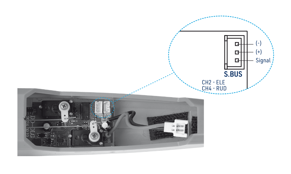
- Gently squeeze the canopy between thumb and forefinger to release both catches, then remove it.
- With the battery disconnected, connect the receiver output to the matching S.BUS port on the decoder/servo board. Secure the receiver to the canopy or behind the board under the wing with hook-and-loop tape or double-sided foam tape.
Secure the receiver, leads and aerial so they cannot come loose or obstruct the servos or linkages.
Receiver battery
Place the receiver battery in the nose and secure it with hook-and-loop tape. Leave it disconnected until the transmitter is on and you are ready for the checks below.
Pre-flight preparation
Check the model when first unpacked, at the start of every flying session, after a hard landing and after any repair or replacement. Factory adjustment does not replace these checks.
Radio and neutral positions
- Switch on the transmitter, then connect the receiver battery and secure it in the nose. The decoder board’s red LED should remain lit. A flashing LED indicates no valid receiver signal; check binding and connections before continuing.
- Bind the receiver to the transmitter according to their instructions. Binding stores the transmitter identity in the receiver so it responds to the correct transmitter.
- Centre the elevator and rudder sticks and trims. Align the elevator with the stabilizer and the rudder with the fin. If necessary, adjust the linkage length by gently reshaping its „Z“ bend with small pliers. Set neutral mechanically; reserve transmitter trim for fine adjustments in flight.
Control directions and throws
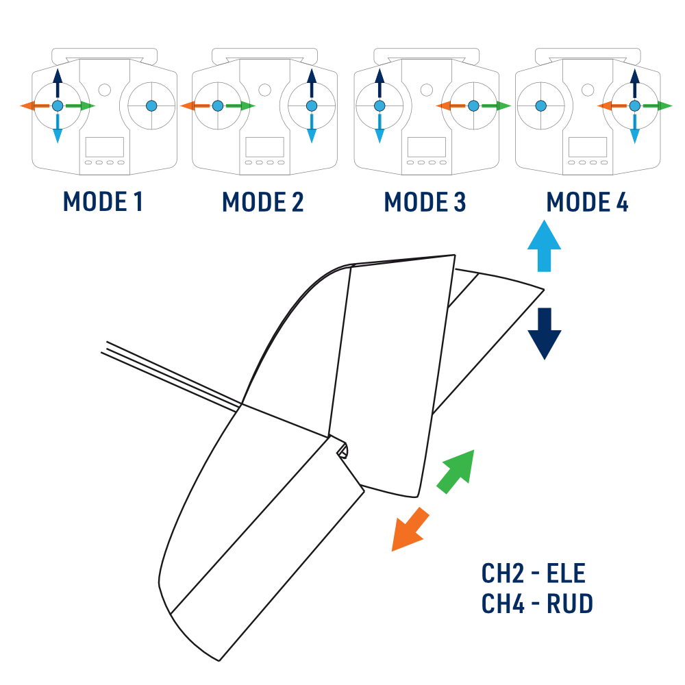
- Pull the elevator stick back: the elevator must move up. Push it forward: the elevator must move down.
- Move the rudder stick right: the rudder must move right when viewed from behind. Move the stick left: the rudder must move left. Correct any reversed response before flying.
- Set the recommended throws using transmitter EPA/ATV or linkage geometry. Moving the linkage closer to the servo shaft reduces throw; moving it farther out increases throw. At the control horn, moving the linkage closer to the hinge increases throw, and moving it farther away reduces throw.
| Control surface | Direction 1 | Direction 2 |
|---|---|---|
| CH4 Rudder | 10–12 mm left | 10–12 mm right |
| CH2 Elevator | 6–7 mm up | 6–7 mm down |
Centre of gravity
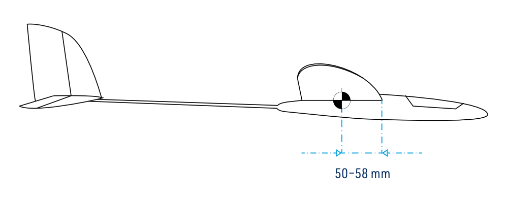
With the model complete and ready to fly, support it 50–58 mm behind the wing leading edge. It should balance level or slightly nose-down. Move the receiver battery to adjust the CG; if needed, add securely fixed ballast to the nose or tail.
An incorrect CG makes the model difficult to control and may prevent safe flight. Check the balance before the first flight and after changing equipment or making repairs.
Preparing to fly
Flying field
Choose a flat grassy area with at least 50 m clear of buildings, vehicles, power lines, trees and other obstacles. A gentle slope facing directly into the wind gives more time for initial glides. A model flying club can provide a suitable site and experienced help.
Weather
Practise in calm conditions until you can control the model confidently. Calm summer evenings are suitable for the maiden flight.
Range check
Follow the radio manufacturer’s range-check procedure. The manual also describes a check with a helper holding the transmitter: carry the powered model at shoulder height in its normal flight attitude and walk at least 60 paces away. Elevator and rudder must respond without jitter or interruptions. Typical visual operating distance for this small model is approximately 50–60 m; always remain close enough to see its orientation clearly.
Do not fly unless the range and control checks are completely successful. Radio range does not replace the need to see the model’s attitude.
Flying
Ask an experienced RC pilot to make or assist with the first flights. Flying requires practice and coordinated reactions. Use small, gentle stick movements and observe their effect; large, abrupt inputs can upset the model.
Hand launch and initial trimming
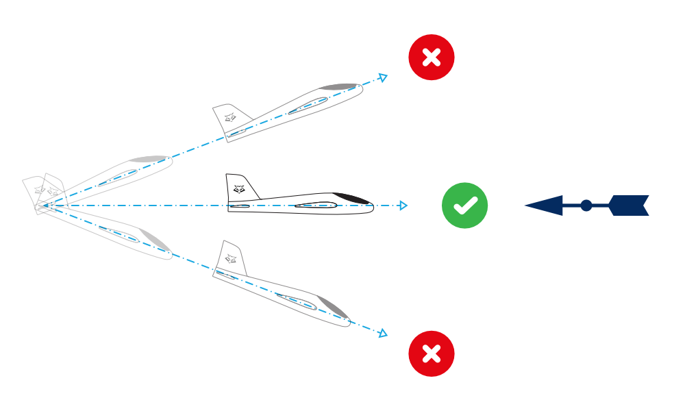
- Check the wind direction, for example with a few blades of grass. Launch into the wind.
- Switch on the transmitter, connect and secure the receiver battery, and latch the canopy.
- Ask a helper to hold the wings level and launch the model gently forward, level or slightly nose-down. Do not throw it nose-up or more than 10° down. Give it enough forward speed to fly; do not merely release it.
- Aim for a steady, shallow glide. If it descends too steeply, apply a little up elevator. If the nose rises sharply, apply down elevator promptly to prevent a stall.
Flying controls
The controls are proportional: more stick movement gives more control-surface movement. Most corrections require only small movements, rarely full travel. Unlike a car, the model banks and moves in three dimensions; anticipate its response.
Elevator
Up elevator raises the nose; down elevator lowers it. A glider can climb only while it has enough energy from launch or speed. It normally trades height for speed; a dive can provide energy for a loop. Excessive climb angle or up elevator reduces airspeed and can cause a stall, with weak control response followed by a drop. Apply down elevator to regain airspeed and control.
Rudder and coordinated turns
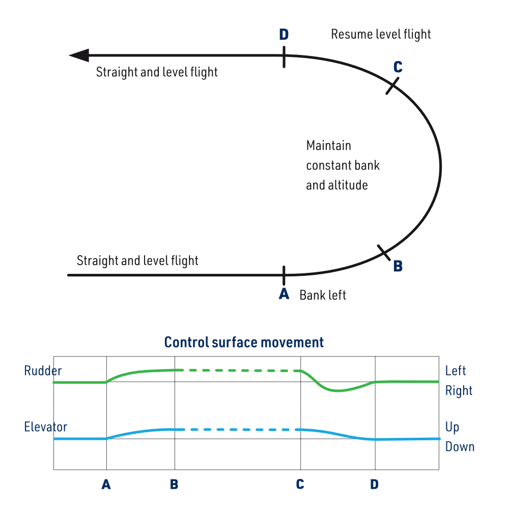
The rudder starts and maintains the bank. Small banks produce wide, gentle turns. Plan normal turns below 30° of bank and never exceed 45° during initial flights. In a bank, less lift supports the model’s weight and the rudder and elevator also act in tilted planes. Add a little up elevator to limit height loss and help the turn. Excessive bank and elevator can reduce speed enough to cause a stall.
For a left turn, apply a little left rudder, then coordinate the elevator. After roughly 3/4 of the turn, begin returning the rudder to neutral and use a little opposite rudder if needed to level the wings. Ease the elevator back to neutral. Start the recovery before the nose reaches the final heading because the model takes time to respond. The dotted B–C control lines show that the exact inputs needed vary with the model’s tendency to tighten or open the turn.
When the model flies towards you, left and right appear reversed. Move the rudder stick towards the low wing you want to raise, as if supporting that wing. Practise until these corrections become natural.
Final trimming
Fly straight into the wind with centred sticks. Correct a persistent turn with opposite rudder trim; use elevator trim to obtain a steady, gentle glide without pitching up and down, excessive speed or near-stalling behaviour.
The model needs airspeed, not ground speed. It travels faster over the ground downwind. Do not try to cancel this by pulling up; doing so can cause a stall, especially when turning into wind near the ground. Launch and land into the wind whenever possible.
Landing
Check the landing area is clear. Begin a straight final approach into the wind at approximately 3–5 m, keeping the wings level and a shallow descent. As you descend through 2–3 m, use only gentle elevator corrections and return the stick towards neutral after each correction. Below approximately 0.5 m, a little up elevator can level the fuselage and soften touchdown. Avoid steep turns near the ground; a controlled landing farther away, or downwind if necessary, is preferable to stalling while trying to turn back.
Discus launch
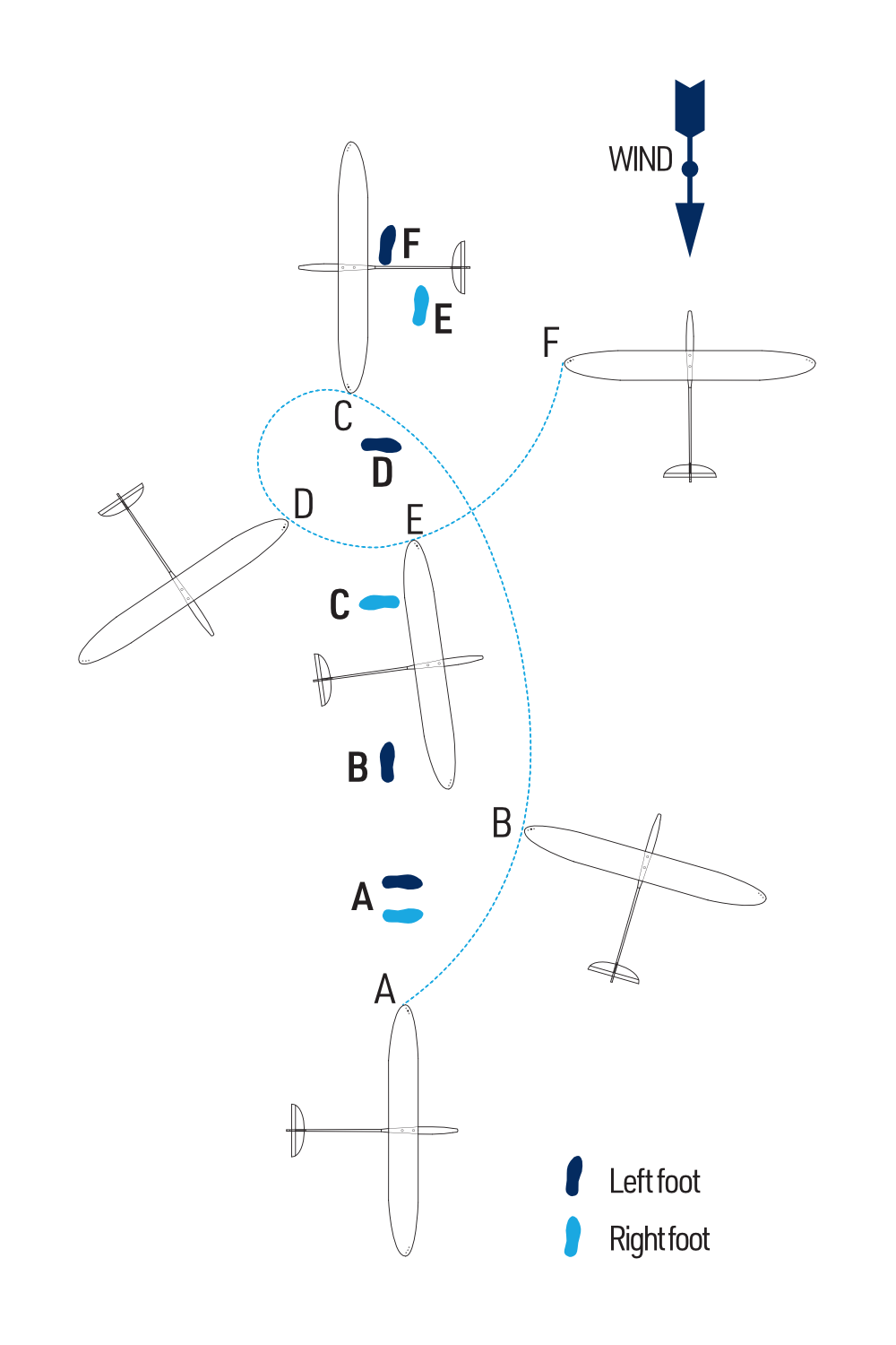
Practise ordinary hand launches and trimming first. The following sequence is for a right-handed pilot using the pin in the left wingtip; reverse it for a left-handed pilot. Keep the entire launch area clear.
Position A: Getting ready
Hook your right index and middle fingers around the pin and rest your thumb gently against the wing leading edge. Face your left shoulder into the wind, with the right wingtip angled approximately 45° towards the ground.
Position B: First step
Take a long step with the left foot while pulling the model forward and upward with your right arm.
Position C: Rotation
Step through with the right foot and turn anticlockwise, keeping the model approximately level and your right arm extended.
Position D: Continued rotation
Let the rotation of your torso accelerate the model. Avoid a forceful independent arm swing during this part of the launch.
Position E: Release
Release the pin and let the model leave your hand directly into the wind as it begins to climb.
Position F: Taking control
Regain your balance and put both hands on the transmitter immediately while watching the model. Be ready to apply down elevator if it climbs too steeply, or a little up elevator if a poor launch sends it towards the ground.
Begin with a shallow launch angle. Once you have mastered the technique and the model, increase the effort and angle gradually, up to approximately 60–80°. Experienced pilots can add two quick steps before the rotation. As the climb loses speed, apply down elevator promptly to establish a level glide before the model stalls. Correct timing gives a smooth transition; acting too early can produce a dive followed by a pitch-up, while acting too late causes a stall.
Hinge adjustment
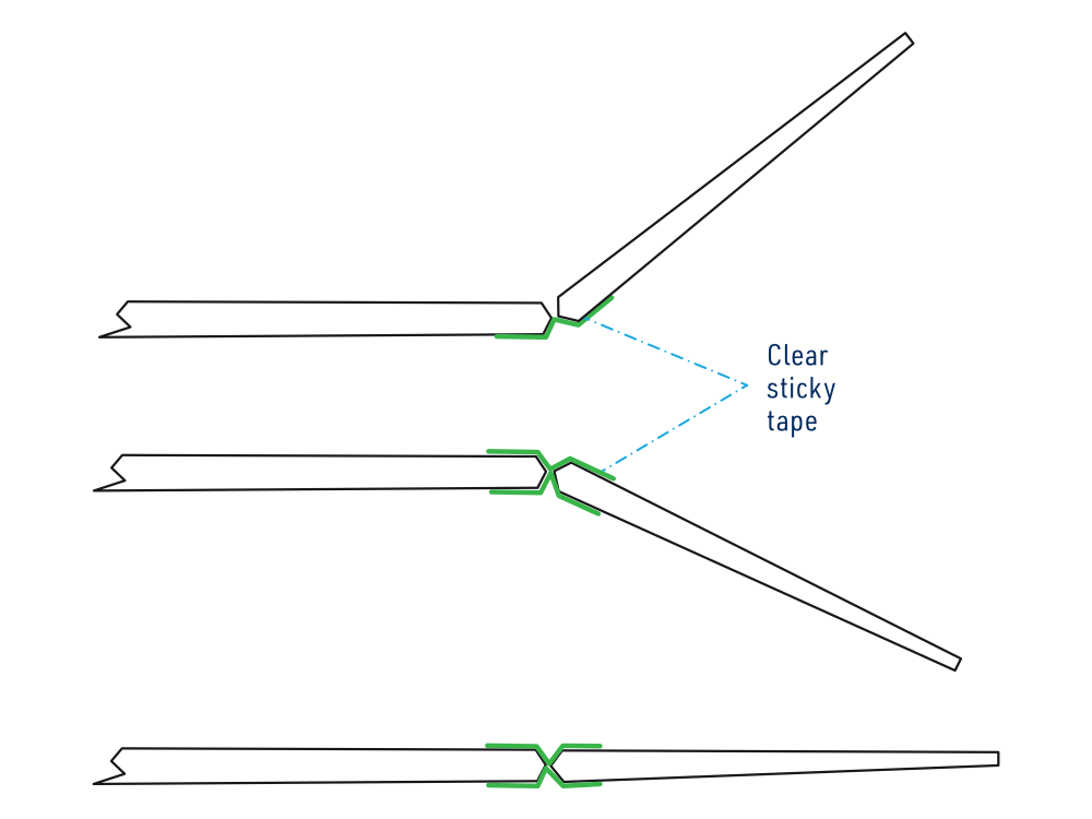
Stiff foam hinges can make control imprecise. Disconnect the receiver battery before working on the linkages.
- Remove the servo arms and gently move the elevator up and down and the rudder left and right by hand 10–20 times to soften the hinges.
- If needed, carefully separate the surfaces with a sharp modeller’s knife and replace the foam hinges with clear hinge tape. Specialist hinge tape or 20mm-wide 3M/Scotch® „Crystal“ tape may be used.
- Apply a strip along one side of the fin edge. Hold the rudder deflected to the opposite side, press the tape into the „V“ gap and then onto the rudder.
- Apply another strip from the other side, pressing it into the „V“ gap and onto the rudder.
- Repeat for the elevator using four strips. Refit the servo arms with the servos centred, secure their screws and repeat the neutral, direction and throw checks.
Appendix
Repairs and maintenance
- Perform a range check at the beginning of every flying session.
- Check control-surface movement before every launch.
- Inspect the model after every landing for damage, loose horns or linkages. Repair all damage before flying again.
- Repair minor EPO damage with CA adhesive or clear adhesive tape. Replace seriously damaged parts with original spares from a KAVAN dealer.
Crash damage is not covered under warranty.
Guarantee
KAVAN Europe s.r.o. guarantees that this model kit is free from defects in both materials and workmanship at the time of sale. This warranty does not cover any parts damaged through use or as a result of modification; under no circumstances shall the liability of the manufacturer and importer exceed the original purchase price of the model kit. KAVAN Europe s.r.o. also reserves the right to change or modify this warranty without prior notice. The model kit is subject to ongoing improvement and refinement, and the manufacturer reserves the right to change the design without prior notice.
Since KAVAN Europe s.r.o. has no control over potential damage during shipping, the method of assembly, or the materials used by the modeller to complete the model, no liability can be assumed or accepted for damages associated with the use of the model assembled by the user. The moment the user decides to use the model they have assembled, they assume full responsibility. If the purchaser is not prepared to accept this responsibility, they should immediately return the kit in its complete and unused condition to the place of purchase.
If your RC model requires service, please follow the guidelines below. Failure to comply with these guidelines may result in the warranty being voided.
- If possible, use the original packaging to pack the model. Do not use the original cardboard box as the final packaging.
- Include a detailed description of how you have used the model and RC kit, as well as the problem you have encountered. Attach a numbered list of the included accessories and provide any additional information that may assist the service department. Date the note and double-check that it includes your full address and phone number.
- Provide your name, address, and phone number where you can be reached during business hours. Include a copy of the model’s proof of purchase.
This warranty card entitles you to a free warranty repair of a product supplied by KAVAN Europe s.r.o. within 24 months. The warranty does not cover normal wear and tear resulting from regular use, as this is a product intended for sports and model-making use, in which individual parts operate under much higher loads than those to which ordinary toys are subjected. The model’s moving parts (motor, servos, and their gears, etc.) are subject to natural wear and tear, and replacement may be necessary over time.
The warranty also does not cover any part of the model or RC kit that was improperly installed, handled roughly or incorrectly, or damaged in a crash, nor does it cover any part of the model or RC kit that was repaired or modified by an unauthorised person. As with other delicate electronic products, do not expose your RC system to high temperatures, low temperatures, humidity, or dusty environments. Do not leave it in direct sunlight for extended periods.
Recycling and waste disposal note (European Union)
Electrical equipment marked with the crossed-out waste bin symbol must not be discarded in the domestic waste; it should be disposed of via the appropriate specialised disposal system. In the countries of the EU (European Union) electrical devices must not be discarded via the normal domestic waste system (WEEE - Waste of Electrical and Electronic Equipment, Directive 2012/19/EU). You can take your unwanted equipment to your nearest public collection point or recycling centre, where it will be disposed of in the proper manner at no charge to you. By disposing of your old equipment in a responsible manner you make an important contribution to the safeguarding of the environment!
EU declaration of conformity
Hereby, KAVAN Europe s.r.o. declares that the model Sling Mini and the included electronic and electric devices are in compliance with the requirements of relevant European directives and harmonized norms. The full text of the Declaration of Conformity is available at www.kavanrc.com/doc/.