KAVAN Norden 1600mm - Instruction manual
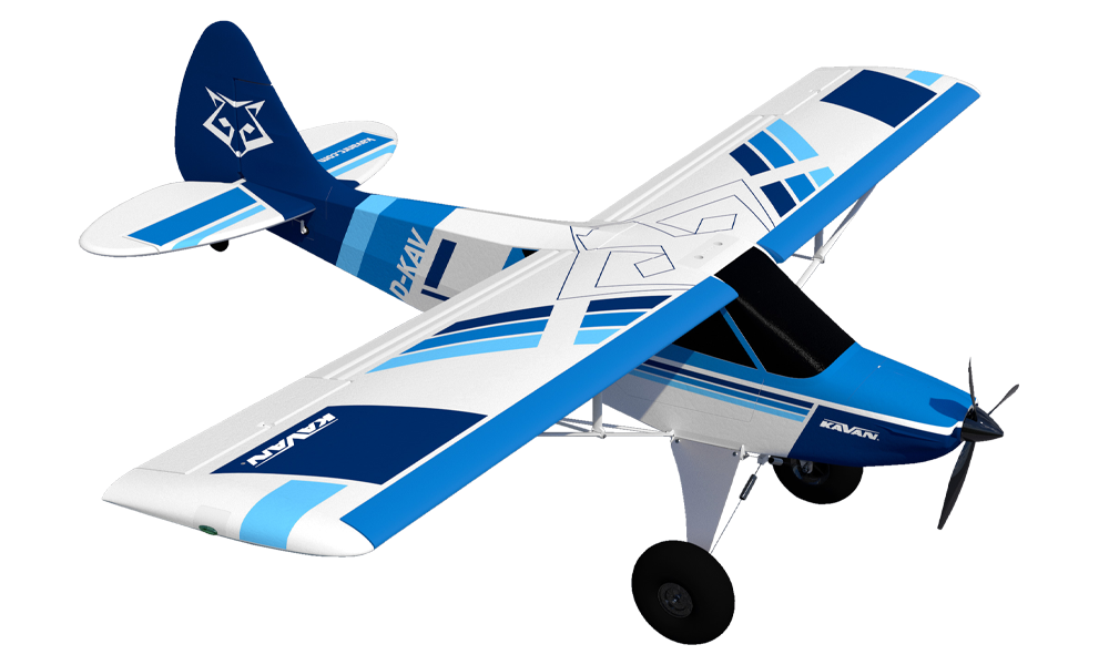
KAVAN Norden - blue
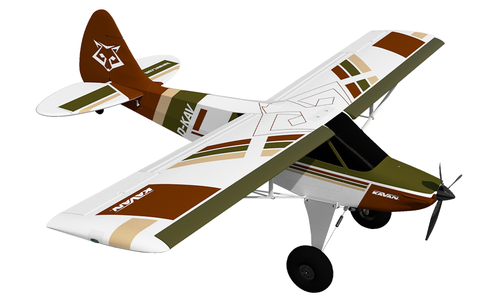
KAVAN Norden - bush
Introduction
The Zlin Aviation Norden is a semi-scale STOL (short take-off and landing) model with flaps and coupled leading-edge slats. Its carbon-reinforced EPO (expanded polyolefin) airframe has an installed brushless power system and six servos. It is intended for pilots who have mastered a trainer with aileron, elevator, rudder and throttle control.
Zlin Aviation Norden
In the middle of the 1990s, the Italian designer Russo Pasquale and his team set out to create an ultra-light tourist aircraft with excellent flight characteristics, short take-off and landing capabilities, with a classical proven design, which would be economical in operation, and easy to build and maintain. They were inspired by the legendary Piper Cub. But during construction, they used the most modern computer technology and the latest achievements in aerodynamics, top materials and avionics, so they created a perfect machine for the beginning of the 21st century.
The very first type of the Savage line entered production in Italy in 1997/1998; in 1999 the manufacturing was relocated to the Czech Republic. Ever since, it has continued with growing success in the Zlin Aviation s.r.o. company, relying on the long tradition of the world-renowned sport aircraft manufacturer and their highly-skilled work team.
The original model manual records more than 500 Savage aircraft delivered at the time of publication. The Norden offers Rotax® 914, 915 and 916 power options rated at 115, 141 and 160 HP, with different propellers, avionics and equipment for touring and bush flying.
Full-size aircraft specifications
| Wingspan | 9.03 m |
|---|---|
| Length | 7.07 m |
| Empty weight | From 365 kg with Rotax 915 iS and lightweight package |
| Maximum take-off weight | 600 kg |
| Maximum speed at sea level | 215 km/h |
| Never-exceed speed (VNE) | 235 km/h |
| Cruise speed | 185 km/h with ground-adjustable propeller / 200 km/h with constant-speed propeller |
| Stall speed with full flaps and slats | 55 km/h |
| Take-off ground roll at maximum take-off weight | Less than 70 m |
| Landing ground roll at maximum take-off weight | Less than 80 m |
| Engine options | Rotax® 914 Turbo 115 HP / 915 iS 141 HP / 916 iS 160 HP |
See the Zlin Aviation Norden manufacturer’s page for full-size aircraft configurations and conditions.
Before you start
- If you are not an experienced RC pilot, plan to have a fully competent pilot check your completed model and help you with your first flights. Even though we have tried to provide you with a thorough instruction manual, RC models are rather complicated and an experienced modeller can quickly check over your model to make sure your first flights are successful.
- Please assemble your model exactly according to these instructions. Do not attempt to modify or change your model in any way, as doing so may adversely change its flying characteristics.
- Before you begin, please check the entire contents of this kit to make sure that no parts are missing or damaged. This will also help you to become familiar with each component of your plane. If you find that any of the parts are either missing or damaged, please contact your dealer immediately for replacement.
- Trial fit each part before glueing it in place. Make sure you are using the correct part and that it fits well before assembling. No amount of glue can make up for a poorly-fitting part.
- The manual contains a drawing showing the default position of the Centre of Gravity (CG) and recommended control surface throws. Please note it is essential to keep the recommended CG position for the first flight otherwise the model could be unstable, hard to control or even unable to fly at all! Start at the forward end of the specified range for greater stability. A rearward CG makes the model more responsive and less stable; adjust it only after becoming familiar with the model, keeping within the specified range.
Your dealer cannot accept kits for return if construction has begun.
Safety precautions
This RC model is not a toy. Use it with care and strictly following the instructions in this manual.
Assemble this model following strictly these instructions. DO NOT modify or alter the model. Failure to do so, the warranty will lapse automatically. Follow the instructions to obtain a safe and solid model at the end of the assembly.
Children under the age of 14 must operate the model under the supervision of an adult.
Assure that the model is in perfect condition before every flight, taking care that all the equipment works correctly and that the model is undamaged in its structure.
Fly only on days with a light breeze and in a safe place away from any obstacles.
General warnings
- An RC aeroplane is not a toy! If misused, it can cause serious bodily harm and damage to property. Fly only in a safe place and follow all instructions and recommendations in this manual. Beware of the propeller! Keep loose items that can get entangled in the propeller away from the spinning propeller, including loose clothing, or other objects such as pencils and screwdrivers. Ensure that your and other people's hands and faces, and animals are kept away from the rotating propeller.
- As the user of this product, you are solely responsible for operating it in a manner that does not endanger yourself and others or result in damage to the product or the property of others. This model is controlled by a radio signal that is subject to interference from many sources outside your control. Interference, equipment failure or pilot error can cause loss of control, so it is advisable to always keep a safe distance in all directions around your model, as this margin will help to avoid collisions or injury.
- Never operate your model with low transmitter batteries.
- Always operate your model in an open area away from power lines, cars, traffic or people. Avoid operating your model in populated areas where injury or damage can occur.
- Carefully follow the directions and warnings for this and any optional support equipment (chargers, rechargeable batteries, etc.) which you use.
- Keep all chemicals, small parts and anything electrical out of the reach of children.
- Moisture causes damage to electronics. Avoid water exposure to all equipment not specifically designed and protected for this purpose.
- The model is mostly made of plastics – it is not fireproof. Keep it away from heat sources, direct sunlight and hot enclosed cars; high temperatures can distort the foam airframe or cause other damage.
- Disconnect the flight battery whenever the model is not in use. Even at zero throttle, the ESC draws current; leaving the battery connected for hours or days can deeply discharge it, damage it and create a fire risk.
Features
- Factory-built, partially assembled, officially licensed semi-scale model
- Carbon-reinforced EPO airframe
- Aileron, elevator, rudder, flap and throttle control
- Double-slotted flaps with mechanically coupled leading-edge slats
- Sprung main undercarriage, large balloon tyres and a steerable tailwheel linked to the rudder
- Functional navigation LED lights
Technical specifications
| Wingspan | 1600 mm |
|---|---|
| Length | 1275 mm |
| Wing area | 44.3 dm² |
| All-up weight | 2350–2400 g |
| Motor | C3548-800 |
| ESC | KAVAN R-50SB Plus, 50 A |
| Propeller | 10×6" 3-blade |
| Installed servos | 6: two aileron, two flap, elevator and rudder |
| Flight battery (not included) | 4S LiPo, 14.8 V, 2600–3300 mAh, at least 30C |
Set contents
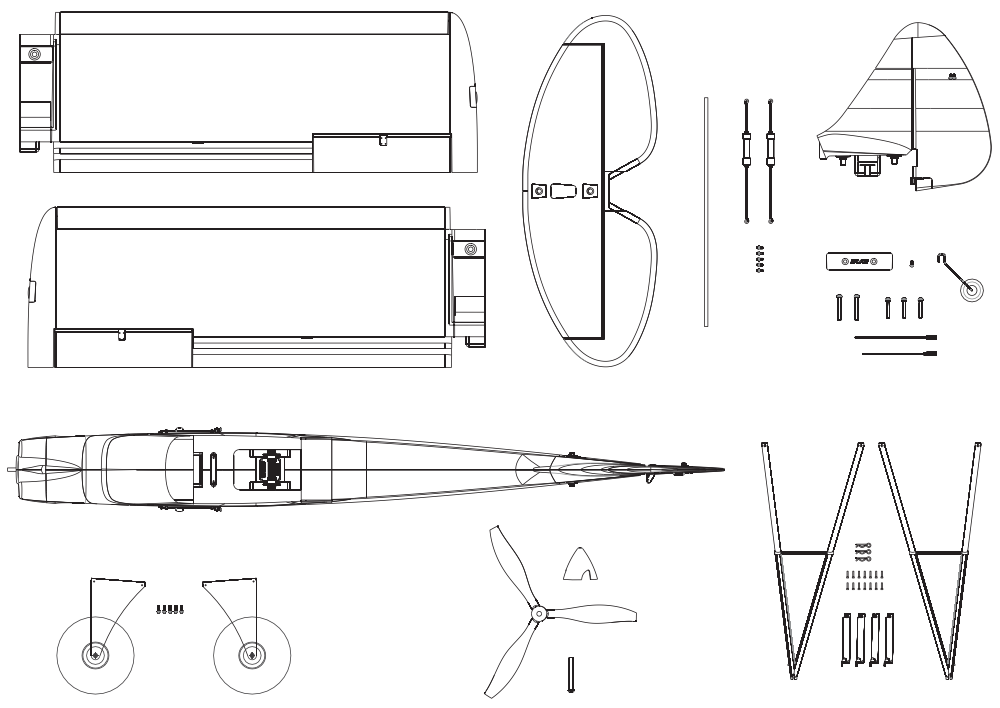
Almost-ready-to-fly EPO model with installed brushless motor, ESC, six servos and LED lights; propeller and spinner, undercarriage, wing and tail fittings, assembly hardware and instruction manual. The transmitter, receiver and flight battery are not included. (Fig. 0)
You will also need
- A transmitter and receiver with at least 6 channels for the standard connection-board arrangement. Independent aileron and flap control requires a computer radio with at least 7 channels and suitable wing adapter leads, such as KAV02.8091.9S.
- The flight battery specified above, a suitable LiPo balance charger and charged transmitter batteries.
- Regular modeller’s tools: precision knife (KAV66.770), screwdrivers, pliers, No. 10 spanner, 1.5 mm and 2.5 mm Allen keys or drivers, and sandpaper.
Main section
Model assembly
Keep the flight battery disconnected during assembly. Remove the propeller before powering the model for initial radio setup. Fit the propeller only after the radio settings and motor rotation have been checked.
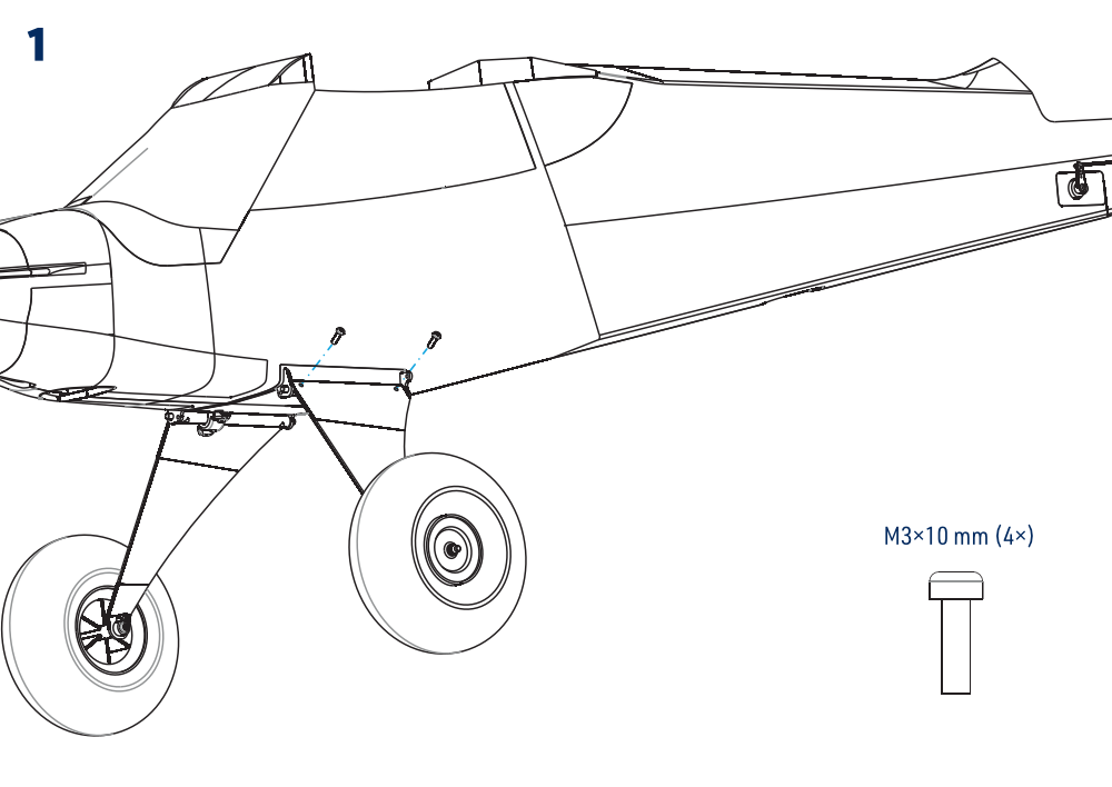
- Attach the main undercarriage legs to the fuselage with four M3×10 mm hex-socket bolts. (Fig. 1)
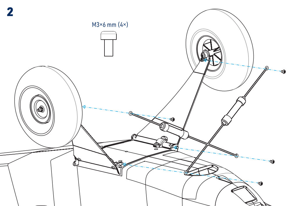
- Fit the sprung undercarriage struts between the fuselage and legs with four M3×6 mm hex-socket bolts and the washers shown. Check that the suspension can move freely. (Fig. 2)
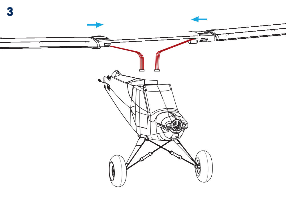
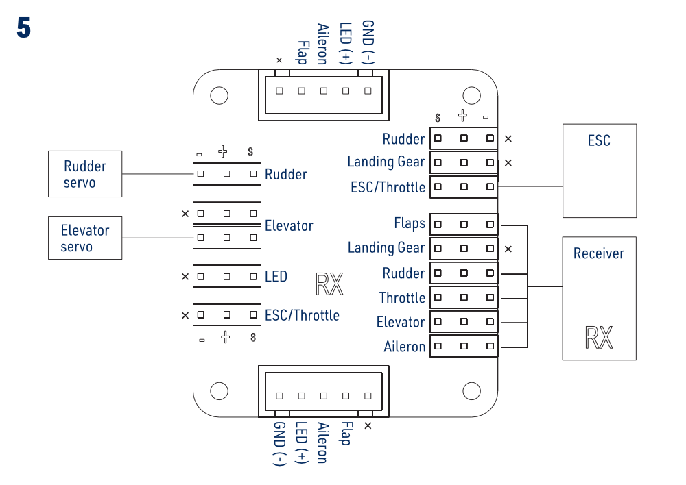
- Slide the wing halves onto the tubular joiner. Route the wing leads into the cockpit and connect the matching multi-connectors according to the wiring diagram. (Fig. 3) (Fig. 5)
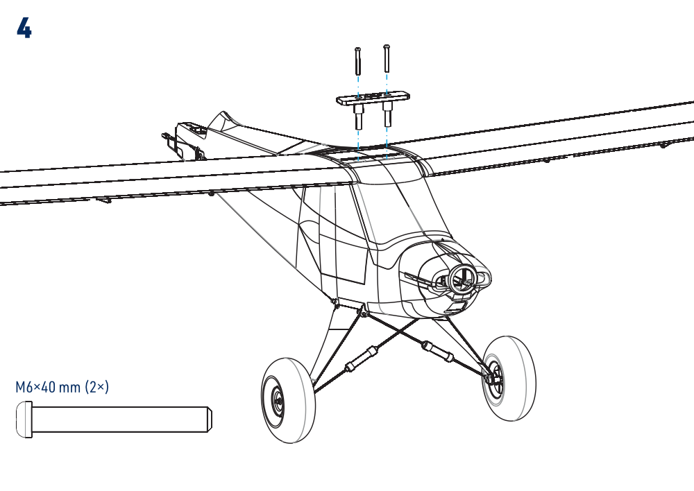
- Fit the wing to the fuselage without trapping cables. Secure it with the plastic joining plate and two M6×40 mm nylon bolts. (Fig. 4)
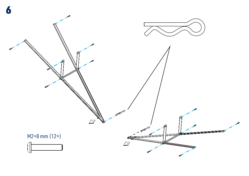
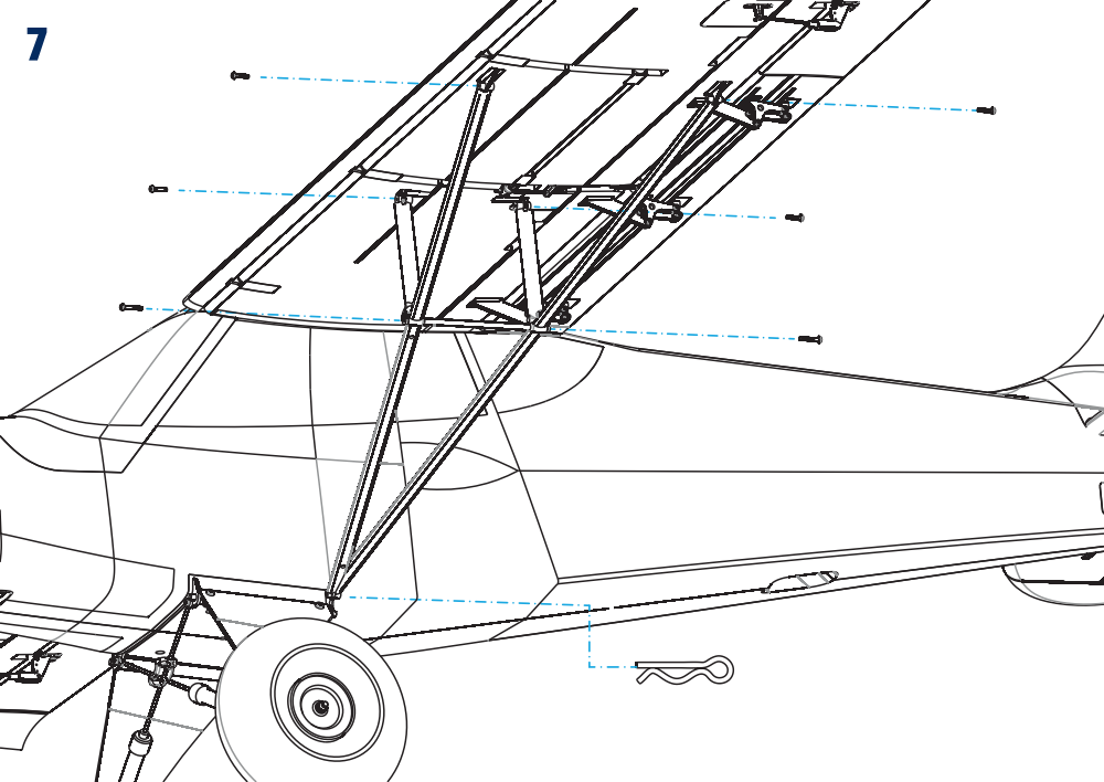
- Assemble both wing-strut sets and secure them to the wing with twelve M2×8 mm hex-socket bolts in total, as shown. Secure each lower attachment to the fuselage with its steel clip and check that every clip is fully engaged. (Fig. 6) (Fig. 7)
- Connect the receiver, servos and ESC as shown. Secure the receiver at the rear of the cockpit with double-sided foam tape or hook-and-loop tape. If the receiver has diversity antennas, arrange their active parts at right angles according to the receiver instructions. (Fig. 5)
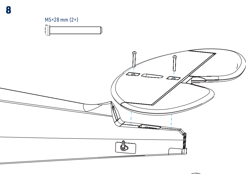
- Attach the horizontal tailplane to the fuselage with two M5×28 mm nylon bolts. (Fig. 8)
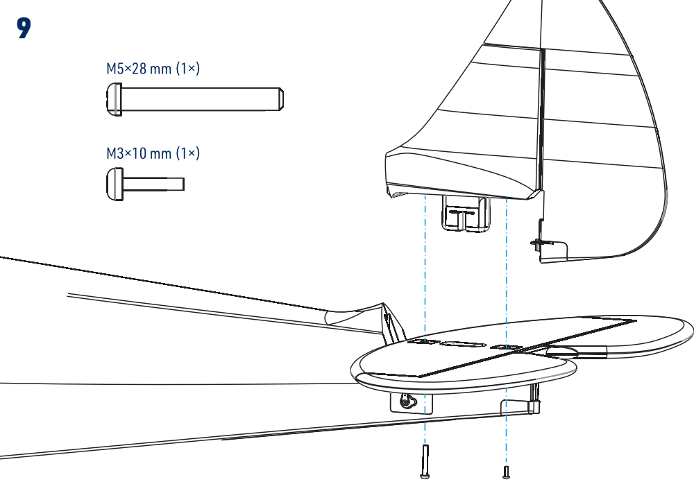
- Fit the fin and secure it with one M5×28 mm nylon bolt and one M3×10 mm hex-socket screw in the positions shown. (Fig. 9)
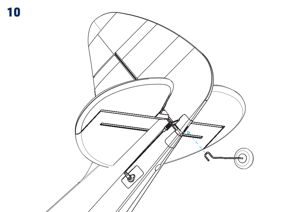
- Insert the tailwheel assembly into the socket at the bottom of the rudder. Check that it is retained and steers with the rudder. (Fig. 10)
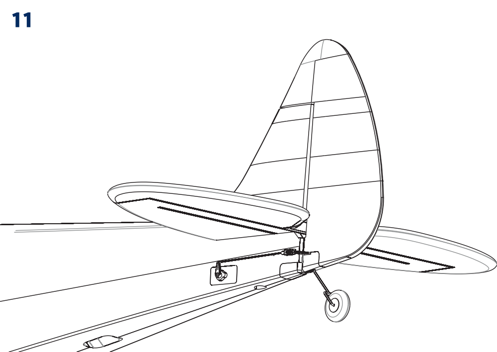
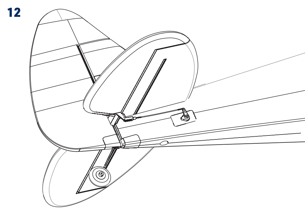
- Fit the rudder and elevator linkages as shown. Leave final neutral adjustment and tightening of the servo-arm pushrod connectors until the radio setup. (Fig. 11) (Fig. 12)
- Open the battery hatch in the nose, position and secure the flight battery, and leave it disconnected until the radio checks. Refit the hatch for the final balance check.
Receiver and connection board
The board connects the wing servos and LEDs through the multi-connectors. Connect the rudder, elevator and ESC to the exact sockets shown, then link the five RX-side function outputs to the matching receiver functions. Observe the signal, positive and negative markings: the two sides have opposite pin orientation. Leave the crossed-out sockets and the landing-gear channel unused. (Fig. 5)
| Drawing label | Meaning |
|---|---|
| Aileron | Ailerons |
| Flap / Flaps | Flaps and coupled slats |
| Elevator | Elevator control |
| Rudder | Rudder control |
| ESC / Throttle | Motor speed controller / throttle control |
| RX / Receiver | Receiver |
| LED / GND | Light positive supply / ground |
| Landing Gear | Unused retract channel in this installation |
| S / + / − | Signal / positive supply / negative supply |
The standard wiring works with a basic 6-channel radio. For independent aileron and flap servo control, use at least 7 channels and bypass the paired wing-servo connections with suitable adapter leads. The slats are mechanically coupled to the flaps and do not require separate servos or channels. The LEDs receive power from the board and cannot be switched remotely through this arrangement.
Assembly drawings
Pre-flight preparation
Radio and control checks
- With the propeller removed, switch on the transmitter with the throttle at minimum, centre the other controls and trims, and connect the flight battery. Check every control direction and adjust the linkages to neutral.
- Centre the elevator and rudder, then tighten the retaining screws of their pushrod connectors on the servo arms. Check that the tailwheel is straight with the rudder neutral and that all controls move freely.
- Calibrate the ESC throttle range using the instructions for the fitted controller. The calibration sequence differs from normal startup; follow it exactly with the propeller removed.
- Set the recommended throws. Moving a linkage closer to the servo shaft or farther from the control-surface pivot reduces the throw; the reverse increases it. Check for free movement throughout the selected travel and secure every clevis pin and servo-arm screw.
- Operate the flaps through their full travel and check that both coupled slats extend and retract symmetrically without binding. Keep the factory linkage geometry unless adjustment is required to restore correct operation.
Control throws
| Recommended throws | Low rate | High rate | ||
|---|---|---|---|---|
| Rate | Expo | Rate | Expo | |
| Ailerons | ±13 mm | 30 % | ±20 mm | 30 % |
| Elevator | ±14 mm | 30 % | ±20 mm | 30 % |
| Rudder | ±35 mm | 20 % | ±45 mm | 20 % |
| Flaps | Take-off: −12 mm down / Landing: −28 mm down | |||
Use low rates for less experienced pilots and normal scale flying. High rates allow experienced pilots to use the model’s full capabilities. Set the expo direction according to the transmitter instructions so the response is softer around neutral.
Recommended mixes
These optional mixes can make the Norden easier to handle. The values below apply with the high-rate throws; aileron differential requires independent aileron channels.
- Aileron → Rudder: 15 mm left rudder at full left aileron command and 15 mm right rudder at full right aileron command.
- Aileron differential: 20 mm up and 10 mm down.
- Flap → Elevator: 2 mm down elevator with take-off flaps and 0 mm elevator compensation with landing flaps.
Motor rotation and propeller
Check rotation during the initial propeller-free test: the motor must turn clockwise when viewed from the cockpit towards the nose. If it turns the wrong way, return the throttle to minimum, disconnect the flight battery and swap any two of the three wires between the motor and ESC. Test again before fitting the propeller.
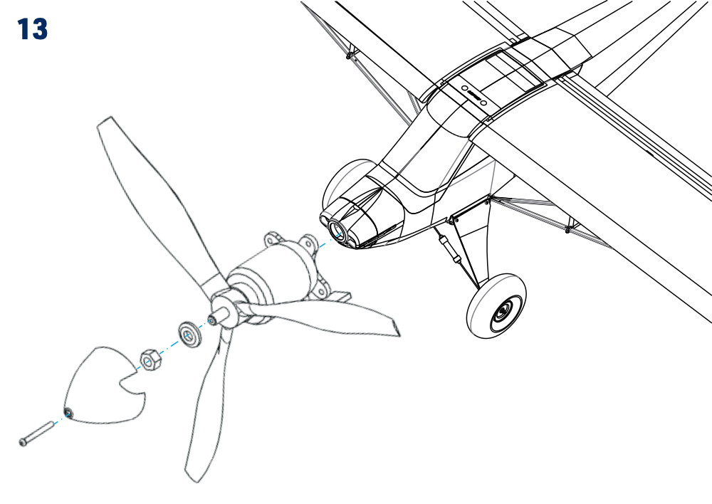
With the battery disconnected, fit the propeller onto the propeller driver and secure it with the washer and nut, using the No. 10 spanner. Fit the spinner and secure it with the M2.5×20 mm bolt. Refit the battery hatch. (Fig. 13)
Centre of gravity
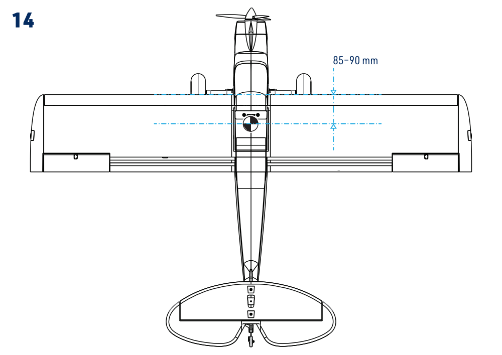
The CG must be 85–90 mm behind the wing leading edge, measured at the wing root as shown. Check with the model complete and its flight battery installed. Adjust the battery position first; if necessary, secure suitable ballast in the nose or tail. (Fig. 14)
Do not fly with the CG outside the specified range. Start at the forward end for the first flight; a rearward CG reduces stability. A small amount of securely fitted ballast is preferable to an incorrectly balanced model.
Range and final checks
Fully charge the flight and transmitter batteries. Check the complete radio installation and perform the range test specified by the radio manufacturer, both with the motor off and at full throttle. Restrain the model securely and keep everyone clear of the propeller and its rotation plane. The range at full throttle must not decrease by more than 10 % compared with the motor-off test. Do not fly unless both tests pass completely.
Flying
The Norden is intended for an intermediate pilot. If you lack experience with this type of model, have an experienced pilot make the first flight, check the trim and help with the initial flights. Choose light wind and a clear, safe flying site. Begin with low rates and become familiar with the model before exploring its aerobatic capabilities.
Appendix
KAVAN R-50SB Plus instructions
Use the KAVAN Plus ESC instruction manual for throttle calibration, startup, programming, protection functions and troubleshooting. Perform initial setup with the propeller removed. Follow the instructions for the R-50SB Plus fitted to this model.
Caution
- Do not install the propeller on the motor when you test the ESC and motor for the first time to verify the correct settings on your radio. Only install your propeller after you have confirmed that the settings on your radio is correct.
- Never use ruptured or punctured battery cells.
- Never use battery packs that are known to overheat.
- Never short circuit battery or motor terminals.
- Always use proper insulation material for cable insulation.
- Always use proper cable connectors.
- Do not exceed the number of cells or servos specified for the ESC.
- Wrong battery polarity will damage the ESC and void the warranty.
- Install the ESC in a suitable location with adequate ventilation for cooling.
- Use only batteries that are supported by the ESC and ensure the correct polarity before connecting.
- Switch your transmitter ON first and ensure the throttle stick is in the minimum position before connecting the battery pack.
- Never switch your transmitter OFF while the battery is connected to your ESC.
- Only connect your battery pack just before flying and do not leave your battery pack connected after flying.
- Handle your model with extreme care once the battery pack is connected and keep away from the propeller at all times. Never stand in-line or directly in front of any rotating parts.
- Do not immerse the ESC under water, do not allow it to get wet while powered up.
- Always fly at a designated flying site and follow the rules and guidelines set by your modeller’s club.
Repairs and maintenance
- Please perform the range check in the beginning of each flying session.
- Before every take off please check the correct control surface movement.
- After every landing check the plane for any damage, loose clevises or push rods, bent or damaged undercarriage, damaged propeller etc. Do not fly again until the damage is repaired.
Although the Norden 1600 model is manufactured of the extra tough and virtually unbreakable expanded polyolefin (EPO) foam, damage or broken parts may occur. A minor damage can be repaired simply gluing the parts together with a cyanoacrylate (CA) glue or with a clear sticky tape. In a case of a major damage it is always better to purchase a brand new spare part. A wide range of genuine spare parts and accessories is available through the KAVAN Europe s.r.o. dealers.
In the unfortunate event of a crash or heavy landing, no matter how minor or major, you must lower the throttle stick to its lowest position as quickly as possible to prevent damage to the electronic speed controller.
Failure to lower the throttle stick and trim to the lowest possible positions in the event of a crash could result in damage to the ESC, which may require replacement of the ESC.
Crash damage is not covered under warranty.
Guarantee
The supplied guarantee follows the applicable legal requirements in the country of purchase. For a claim, contact the retailer from whom you purchased the model. KAVAN Europe s.r.o. guarantees that this model kit is free from defects in both materials and workmanship at the time of sale. This warranty does not cover any parts damaged through use or as a result of modification; subject to applicable law, the liability of the manufacturer and importer is limited to the original purchase price of the model kit. This limitation does not apply where a court imposes unlimited liability for proven intent or gross negligence. KAVAN Europe s.r.o. also reserves the right to change or modify this warranty without prior notice. The model kit is subject to ongoing improvement and refinement, and the manufacturer reserves the right to change the design without prior notice.
Since KAVAN Europe s.r.o. has no control over potential damage during shipping, the method of assembly, or the materials used by the modeller to complete the model, no liability can be assumed or accepted for damages associated with the use of the model assembled by the user. The moment the user decides to use the model they have assembled, they assume full responsibility. If the purchaser is not prepared to accept this responsibility, they should immediately return the kit in its complete and unused condition to the place of purchase.
If your RC model requires service, please follow the guidelines below. Failure to comply with these guidelines may result in the warranty being voided.
- If possible, use the original packaging to pack the model. Do not use the original cardboard box as the final packaging.
- Include a detailed description of how you have used the model and RC kit, as well as the problem you have encountered. Attach a numbered list of the included accessories and provide any additional information that may assist the service department. Date the note and double-check that it includes your full address and phone number.
- Provide your name, address, and phone number where you can be reached during business hours. Include a copy of the model’s proof of purchase.
This warranty card entitles you to a free warranty repair of a product supplied by KAVAN Europe s.r.o. within 24 months. The warranty does not cover normal wear and tear resulting from regular use, as this is a product intended for sports and model-making use, in which individual parts operate under much higher loads than those to which ordinary toys are subjected. The model’s moving parts (motor, servos, and their gears, etc.) are subject to natural wear and tear, and replacement may be necessary over time.
The warranty also does not cover any part of the model or RC kit that was improperly installed, handled roughly or incorrectly, or damaged in a crash, nor does it cover any part of the model or RC kit that was repaired or modified by an unauthorised person. As with other delicate electronic products, do not expose your RC system to high temperatures, low temperatures, humidity, or dusty environments. Do not leave it in direct sunlight for extended periods.
The guarantee also excludes faults caused by incorrect wiring or reversed polarity, late or omitted maintenance, operation outside the specified limits, and accessories or repairs not approved by KAVAN Europe s.r.o. Avoid strong mechanical shocks and user-applied waterproof coatings on the RC electronics.
Recycling and waste disposal note (European Union)
Electrical equipment marked with the crossed-out waste bin symbol must not be discarded in the domestic waste; it should be disposed of via the appropriate specialised disposal system. In the countries of the EU (European Union) electrical devices must not be discarded via the normal domestic waste system (WEEE - Waste of Electrical and Electronic Equipment, Directive 2012/19/EU). You can take your unwanted equipment to your nearest public collection point or recycling centre, where it will be disposed of in the proper manner at no charge to you. By disposing of your old equipment in a responsible manner you make an important contribution to the safeguarding of the environment!
EU declaration of conformity
Hereby, KAVAN Europe s.r.o. declares that the model Norden 1600 and the included electronic and electric devices are in compliance with the requirements of relevant European directives and harmonized norms. The full text of the Declaration of Conformity is available at kavanrc.com/doc.