KAVAN FS400AR - Instruction manual
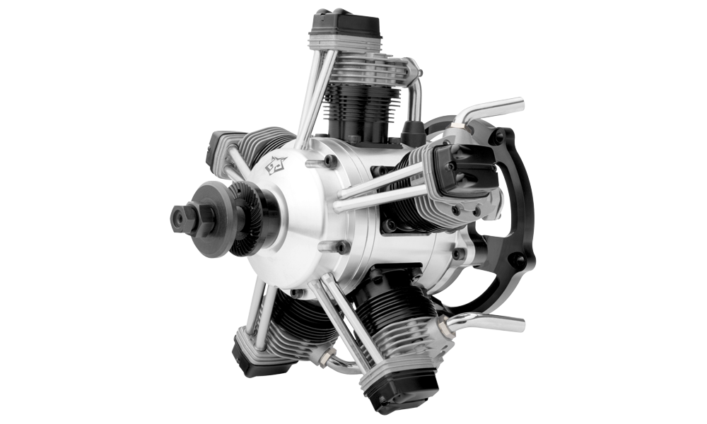
KAVAN FS400AR
Introduction
The FS400AR is a five-cylinder radial overhead-valve four-stroke glow engine with a total displacement of approximately 64 cm³ (63.98 cm³ in the original manual). It is designed for large aircraft, such as 1:4 scale models, and modellers seeking smoother operation than larger two-stroke engines provide.
Engine overview
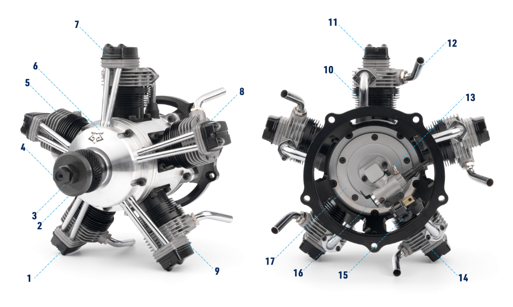
- Cylinder #4
- Propeller washer
- Propeller nut
- Lock nut
- Cylinder #5
- Front housing
- Cylinder #1
- Cylinder #2
- Cylinder #3
- Intake pipe
- Rocker cover
- Exhaust pipe
- Fuel inlet
- Cylinder head
- Choke valve
- Carburettor throttle
- Back plate
Before attempting to operate your engine, please read through this instruction manual to familiarize yourself with the controls and other features of the engine. Also, pay careful attention to the recommendations contained in the Safety Notes and Warnings chapter of this instruction manual.
Specifications
| Displacement | 5×12.8 cm³ (5×0.781 in³) |
|---|---|
| Bore | 26.5 mm (1.043″) |
| Stroke | 23.2 mm (0.913″) |
| Power | 5.55 kW at 7250 rpm |
| Operating speed | 1800–9000 rpm |
| Weight including engine mount | 2800 g (6.17 lb) |
| Recommended fuel tank | 500–600 ml |
Safety notes and warnings
The engine is not a toy. It is a powerful internal-combustion machine that can injure you or others if misused.
Before the first start, read the entire manual, familiarise yourself with the engine’s controls and features, and pay particular attention to the safety instructions.
Following these instructions helps ensure reliable and safe operation. You are responsible for operating your engine safely; always act thoughtfully and with care. Misuse or failure to observe safety precautions can cause serious injury.
- Do not allow especially small children and other spectators, who could be injured as a result of operating your engine, to come too close. The safe distance is at least 5–6 m (20 feet) away from the engine while it is running. No one should stand in line with the rotating propeller!
- Mount the engine securely in the plane, or on a proper engine test stand using high quality steel hex cap screws, washers and locknuts. Follow the mounting recommendations on the airplane‘s plan and/or instruction manual, or in the test stand described in the directions. DO NOT clamp this engine into a vice!
- Use the correct size propeller and follow the recommended mounting procedures. Follow this instruction manual, the building plan/kit instruction manual; ask an experienced modeller or skilled model shop personnel if in doubts.
- Install your propeller properly (looking from the cockpit of your model, the propeller of an engine installed in the nose rotates clockwise, looking from the front of the model it rotates counter clockwise). Use a proper wrench to tighten the propeller nut. Do NOT use pliers. Four stroke engines and large two stroke ones should use special safety locking propeller nuts.
- Never touch, or allow any object to come into contact with, the rotating propeller and do not crouch over the engine when it is running.
- Beware of the prop, protect your fingers. When hand cranking your engine, always us the „chicken stick“ (available in model hobby shops) or strong leather glove. Preferably, use an electric starter.
- After starting, adjust the main needle only from a safe position behind the rotating propeller.
- To stop your engine, adjust the throttle linkage so that the engine stops when the throttle stick and trim lever on the transmitter are fully retarded. Alternatively, the engine may be stopped by cutting off the fuel supply. Never try to stop the engine physically.
- Discard any propeller which has become split, cracked, nicked or otherwise rendered unsafe. Never attempt to repair such a propeller: destroy it. Do not modify a propeller in any way. Also, check the tightness of all the screws and nuts regularly and frequently
- If you have to carry the model to the take-off point with the engine running, be especially cautious. Keep the propeller pointed away from you and walk well clear of spectators.
- Do not fly your model near or under power lines.
Safety tips
- The wearing of safety glasses is strongly recommended.
- Do not start your engine in an area containing loose gravel or sand. The propeller may throw such material in your face and eyes and cause injury.
- Take care that loose clothing (ties, shirt sleeves, scarves, etc.) do not come into contact with the propeller. Do not carry loose objects (such as pencils, screwdrivers, etc.) in a shirt pocket from where they could fall through the propeller arc.
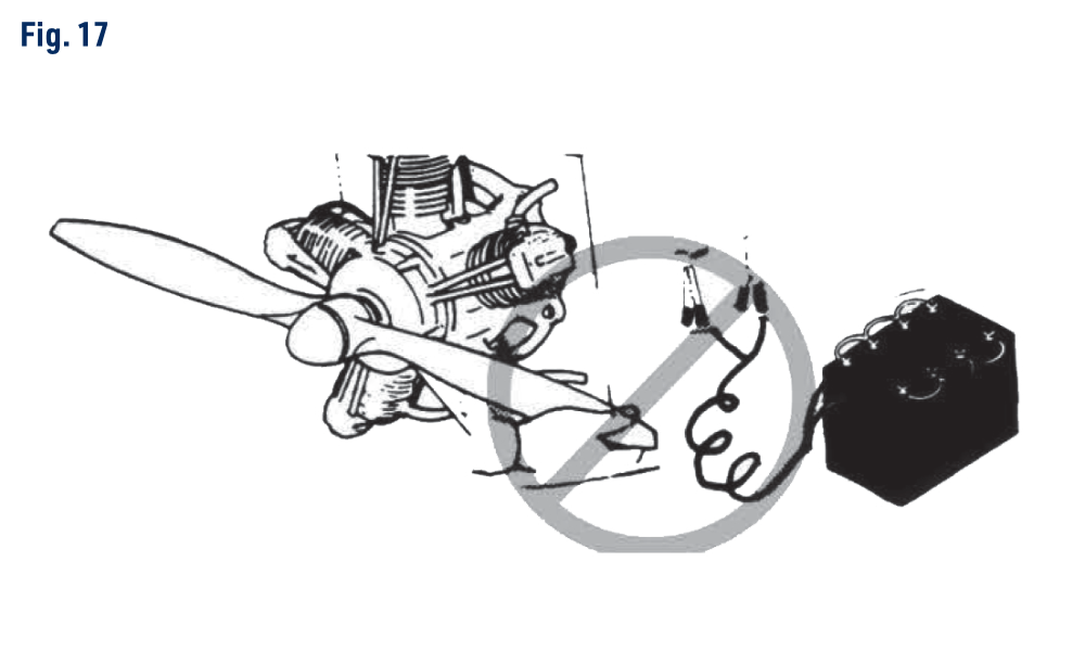
- Take care that the glow plug clip or battery leads do not come into contact with the propeller.
- If you install a spinner, make sure that the slots for the propeller blades do not touch the blade roots and weaken them.
Warnings
- Model engine fuel is poisonous. Do not allow it to come into contact with the eyes or mouth. Always store it in a clearly marked container and in a cool, dark place out of the reach of children.
- Model engine fuel is also highly flammable. Keep it away from open flame, excessive heat, sources of sparks, or anything else which might ignite it. Do not smoke or allow anyone else to smoke, near to it.
- The engine and exhaust pipes become very hot. Do not touch them before they cool; the cylinder heads and exhausts in particular can cause serious burns.
- Never operate your engine in an enclosed space. Model engines, like automobile engines, exhaust deadly carbon-monoxide. Run your engine only in an open area.
- Remember: Operating any model requires experience and constant attention to safety rules. Model airplanes, boats or cars have a lot of energy that can cause serious personal injury or significant property damage.
Always proceed with caution! If you are a beginner, ask for help and advice from an experienced modeller! Before trying to start the engine for the first time, carefully read the instructions and safety rules!
Supplied accessories
The original manual lists a radial engine mount, 10 glow-plug leads (five fitted and five spare), five four-stroke glow plugs, a display stand, a tool kit, mounting screws, a needle-valve extension cable, a choke rod and an AWG16 ground lead. The current catalogue lists five glow leads; check the contents of the supplied set against its packing list.
Main section
Engine installation
The FS400AR includes a strong one-piece CNC-machined aluminium radial-type mount for easy and secure installation to the firewall of your aircraft. When installing the FS400AR to the firewall of your aircraft, it is imperative that the firewall is made from aircraft-grade plywood at least 15 mm thick, strong and secure, and firmly attached to the structure of your aircraft.
Installation procedure
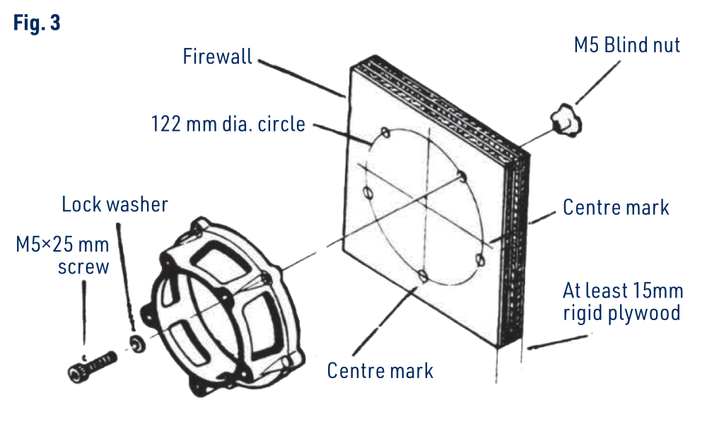
- Locate the centre of the firewall.
- Place the engine on a sheet of paper, mount down. Using a sharp pencil, outline the outside radius of the engine mount.
- Then mark the exact location of the mounting holes.
- Take engine off sheet of paper, and find centre of outlined engine mount.
- Tape sheet of paper, matching centre of mount to centre of firewall.
- Mark the holes on the Ø122 mm mounting circle and drill for the M5×25 mm mounting screws. Check the pattern against the supplied mount before drilling.
- Secure the engine to the firewall, using the supplied screws, nuts and washers, making sure that the „KAVAN“ logo on the front housing is facing up.
Needle-valve extension
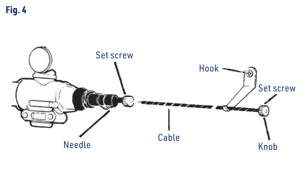
The needle-valve supplied with your FS400AR is designed to use an extension so that the needle valve may be adjusted from outside the airplane once the engine is enclosed within the fuselage. A flexible cable with knob at one end, approximately Ø1.6 mm, should be inserted into the needle valve‘s centre hole. Secure cable by tightening the set screw in the needle valve with the small Hex key included with your engine. On the outside end of cable, secure the included knob with the set screw using the small hex key.
Do not use an excessively long extension cable that is unsupported, as this may cause a vibration which might affect the needle valve setting and/or damage the needle valve thread. If you need to have a longer extension cable so that the needle valve can be adjusted from outside of the airplane, always provide a suitable support at the outer end. Additionally, be sure not to position the support for the needle valve extension near the exhaust pipe.
The carburettor cannot be reversed in order to reverse the needle valve location.
Choke valve
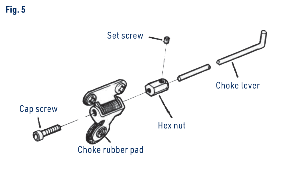
- The choke valve operating lever can be located either on the left or right side by reversing the hexagon nut and cap screw.
- Unscrew the cap screw while holding the hexagon nut with the included wrench supplied, and refit the lever to your required location.
- If the supplied rod is too long, cut it to required length. An unnecessarily long rod may tend to vibrate. The rod should be as short as possible or should have its outer end supported.
Exhaust-pipe adjustment
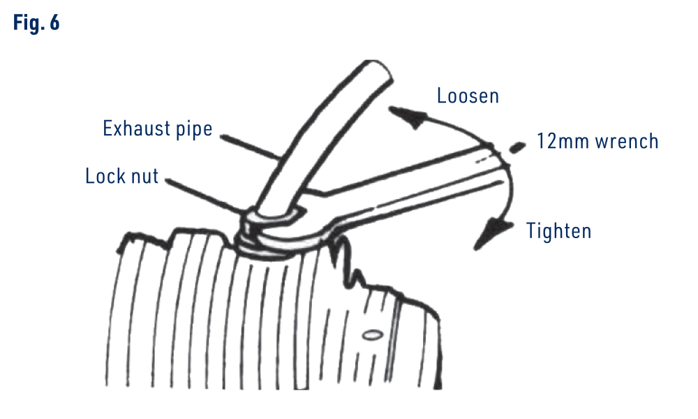
The direction of the exhaust pipes may be altered in accordance with individual installation requirements. The angle is easily adjusted by loosening the nut that secures the exhaust pipe to the cylinder head. Use the supplied 12 mm wrench.
Carburettor cleanliness
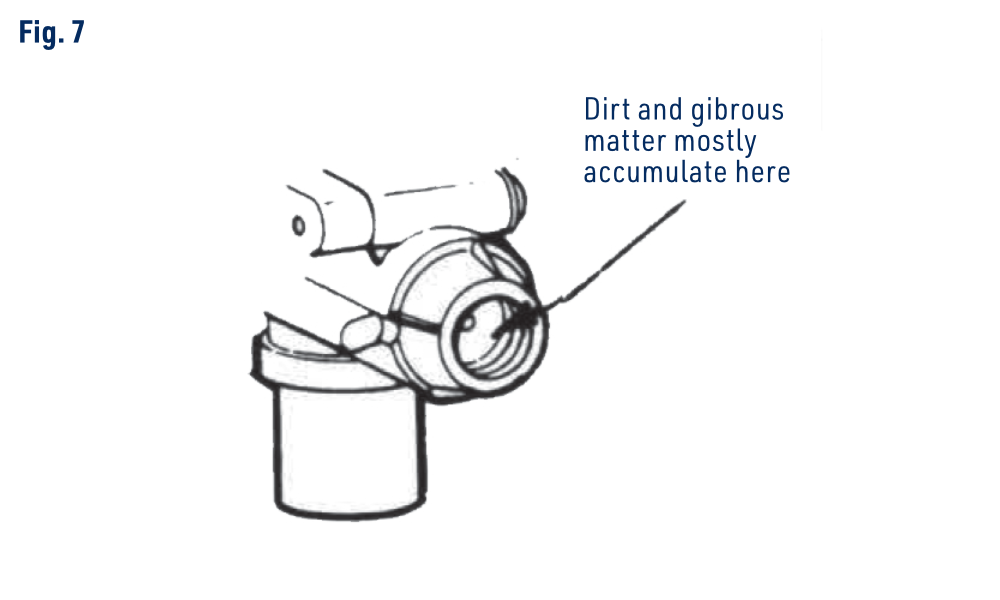
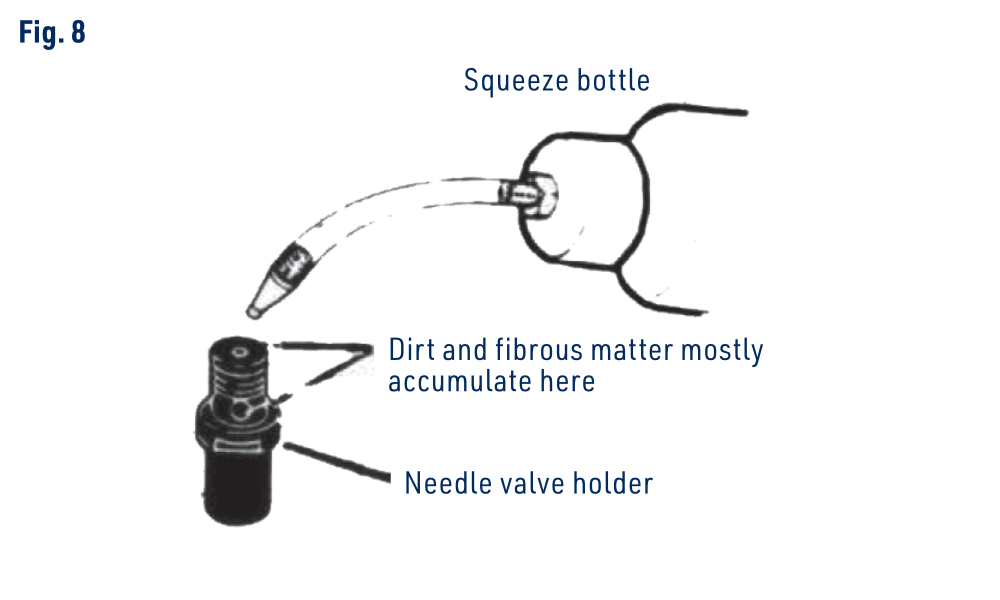
Fuel entering the carburettor must be clean. Use a filter when filling the tank and a good-quality in-line filter between the tank and carburettor. Additionally, occasionally remove the needle valve holder from the carburettor and rinse out the locations shown in (Fig. 7)+(Fig. 8) with methanol or fuel. Be careful not to lose the gasket when removing the needle valve holder from the carburettor.
Choosing a propeller
The choice of propeller for your FS400AR depends on the size, weight, and performance level of the model. Determine the best propeller size after practical experiment. As a starting point, refer to the propeller chart below for expected rpm with specific propellers:
| Propeller | rpm |
|---|---|
| 18×10″ | 8200–8400 |
| 18×12″ | 7200–7400 |
| 18×14″ | 6800–7000 |
| 20×8″ | Source range 7900–7200 rpm is inconsistent; confirmation pending |
| 20×10″ | 7000–7200 |
| 22×8″ | 6900–7100 |
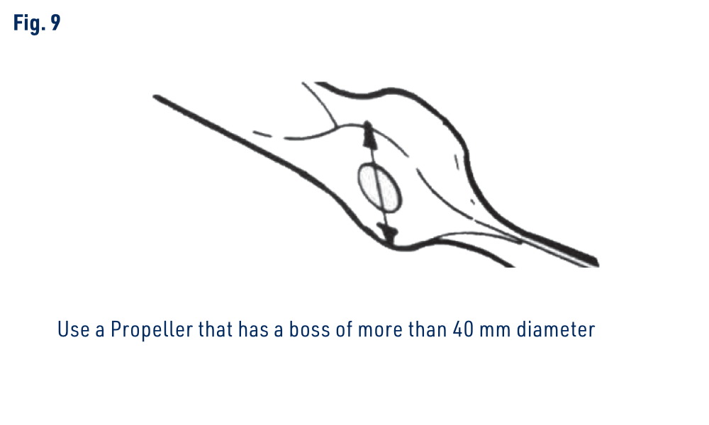
Use a propeller with a hub diameter greater than 40 mm. Use only well-balanced propellers. An unbalanced propeller causes vibration and loss of power. It is also important to ensure that the propeller has no nicks, splits, or cracks and shows no other signs of wear.
During every operation, including starting and needle adjustment, keep your face, hands and body away from the propeller arc. Follow the Safety notes and warnings.
Securing the propeller
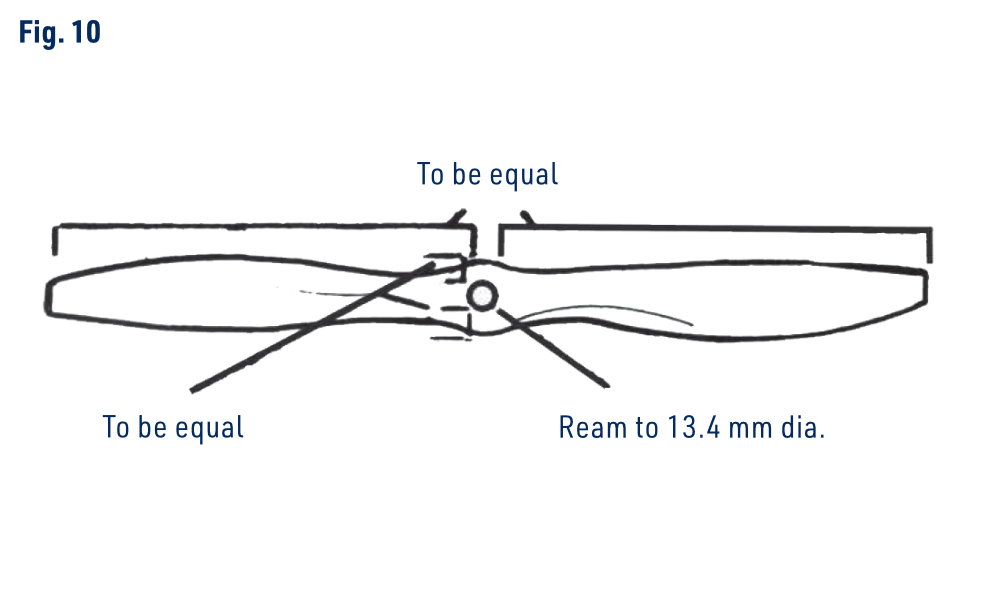
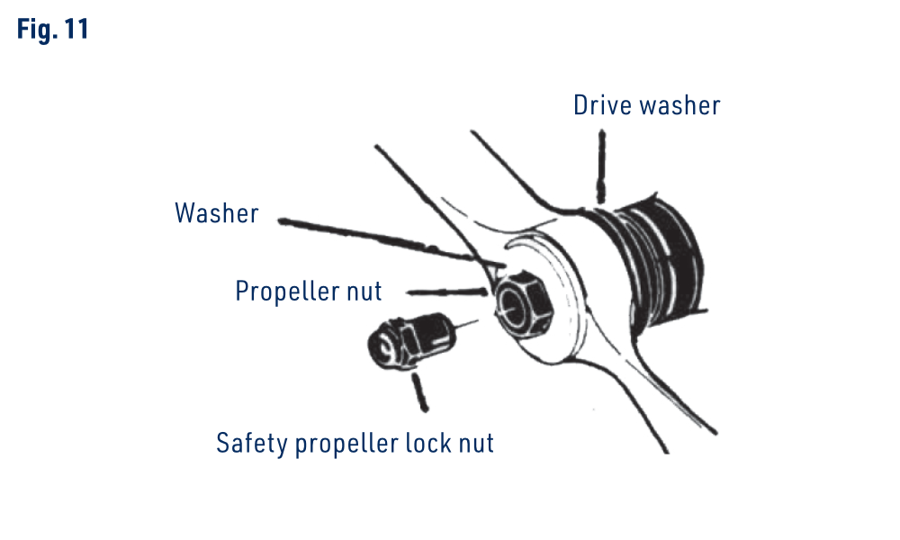
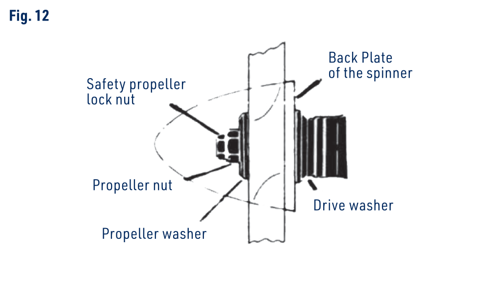
When securing the selected propeller to the FS400AR, it is recommended to use the Propeller Safety Locknut Assembly, included with the engine, to prevent the propeller from flying off or splintering, even if it loosens. Be sure to securely tighten the propeller nut.
The supplied safety locknut suits a propeller hub thickness of 18–28 mm (23/32″–1⅛″). If the hub is thinner than 18 mm, fit a suitable additional washer between the propeller washer and propeller nut. Ensure full, secure engagement of both nuts.
Install the propeller as follows:
- Ream the propeller centre hole to Ø13.4 mm, as specified in the metric drawing. The English text gives approximately 17/32″; check the fit to the actual drive assembly without creating excess clearance.
- Balance the propeller.
- Ensure that the Woodruff Key and drive washer are properly and firmly attached. The Woodruff key allows the drive washer to lock into place, as it is the only place where the washer can slide into place to meet the crankshaft.
- Fit the propeller nut and washer to the propeller, and screw onto the engine shaft. Tighten the nut firmly with wrench.
- Insert the Propeller Safety Locknut Assembly and tighten firmly with wrench, being sure not to use excessive force.
- It is important to remember, especially with wooden propellers, that there is a tendency for propeller materials to shrink due to wear or to heat. Always check to ensure that the propeller is properly secured to the shaft. Tighten the propeller nut if necessary after loosening the Propeller Safety Locknut. Re-tighten the locknut once propeller nut is secure.
Glow-plug heating
A 4 cycle engine fires every 2 revolutions, and it is imperative that a proper glow plug be fitted to the FS400AR. Five 4 Cycle Glow Plugs are included with the FS400AR. The original glow plug is recommended for best all around performance with this engine.
If you choose glow plugs other than the original 4 Cycle, it is important to use the same type for all cylinders.
Onboard glow system
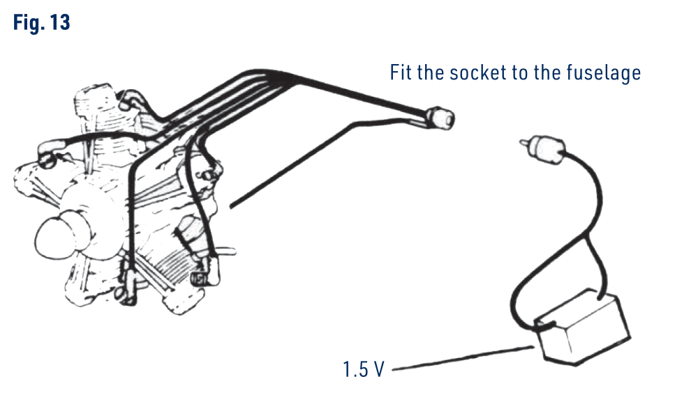
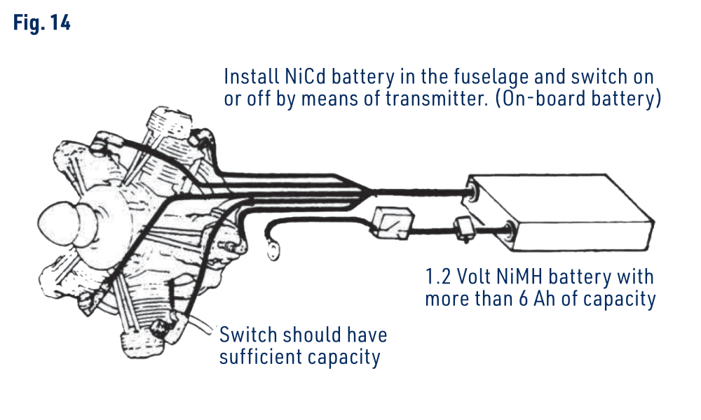
For best performance, use an onboard battery to ignite the glow plugs when the throttle is set at half throttle or less. The onboard glow will ensure that all glow plugs stay „hot“ even when the engine rpm slows.
- The FS400AR includes 10 (5 for spare use) spring loaded connectors for connecting the glow plugs to the battery. These special connecting heads will snap onto the head of the glow plug to ensure firm contact.
- Once the connectors are secure to the glow plugs, join the 5 glow plug leads together. If the connecting wires need to be extended once they have been joined, use an AWG16 wire (approximately 1.3 mm²) or a larger cross-section to employ a single lead.
- The glow plug wires should be connected to the positive battery terminal when in use.
- The Ground Wire can be connected to the engine mount, and will connect to the negative battery terminal.
- A switch rated for at least 15 A should be wired into the negative lead to turn the system on and off during transport and priming procedures. The switch should be easily accessible on the outside of the aircraft.
- A second switch rated for at least 15 A should be wired into the same line as well and linked to the throttle servo to turn on when the throttle is set at half throttle or below. (Or you can use a suitable electronic glow heating device available in model hobby shops.)
- Use a glow supply providing approximately 1.2–1.5 V at the plugs and a battery capacity of 6–10 Ah for the onboard system. The source describes four or five Sub-C cells in parallel; use a properly assembled pack of matched cells. The Czech manual specifies NiMH, while the original English text also mentions NiCd. A lead-acid source requires voltage reduction as described in Glow-plug battery; never connect a 2V cell directly to the plugs.
- As an option, you may want to have a separate power source to use during starting procedures. The use of a separate battery will extend the time between charges of the on-board battery.
- Remember, if using an external battery, the onboard battery should be off. See Glow-plug battery.
Glow-plug battery
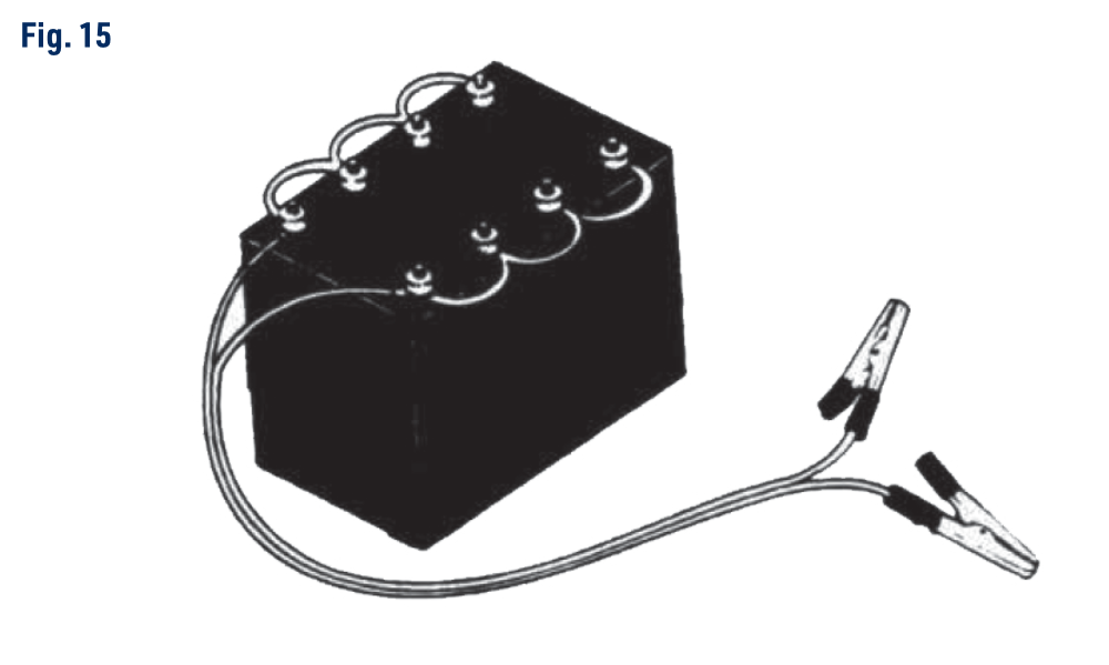
When starting the FS400AR, it is necessary to use a glow plug battery of large capacity, 10 Ah or greater to heat 5 glow plugs simultaneously. A heavy duty 1.5V dry battery or a 1.2V rechargeable NiMH battery (NiCd in the original English source) may be used. A 2V lead-acid cell (accumulator) may also be used but only if a method for reducing the voltage at the plugs is in place, since the plugs are only rated at 1.5 V. Follow the voltage-reduction precautions below for a 2V source.
- If a 2V lead-acid rechargeable cell is used, it is necessary to reduce the applied voltage at the glow plugs to approximately 1.5 V. The recommended method is to insert an appropriate resistor in each individual plug lead. It is seriously discouraged to use a rheostat attached to the 2V cell, or to use extra long leads of at least 2 meters in length, to obtain the required drop in voltage. The disadvantage of this system is that if 1 glow plug should become disconnected, voltage to the remaining 4 glow plugs will be increased dramatically and may cause burning out of the elements.
Fuel
For consistent performance and long life of the engine, it is advisable to use good quality fuel containing not less than 18 % lubricant, castor oil preferred, until a total of 1–2 hours of break-in has been achieved. The original manual mentions reducing oil after break-in, but gives no lower limit and warns of shorter life. Retain at least 18 % oil unless KAVAN confirms a different formulation. The original break-in mixture is shown below. The current catalogue recommends KAVAN 4T Air 5 % nitro for break-in and normal operation, with 10 % or 15 % nitro options after break-in, and at least 18 % castor oil or a castor/synthetic blend for castor-based fuels. These recommendations differ; confirm the approved fuel for your engine before operating it.
| Original manual break-in fuel | Proportion |
|---|---|
| Nitromethane | 10–15 % |
| Castor oil | 18 % |
| Methanol | 67–72 % |
Lubrication
- All parts of the FS400AR are automatically lubricated by the oil content of the fuel mixture.
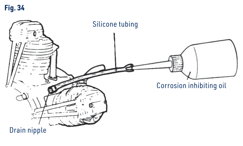
- During the running of the engine, as well as while the engine is sitting properly mounted with the drain nipple pointed down, the excess oil will leave through the drain nipple. To protect your airplane, connect silicone tubing to the drain nipple and have it release the oil outside of your aircraft.
- After you complete your day of flight, let the engine consume residual fuel after safely disconnecting the supply from behind the propeller to remove residual fuel from the engine. The remaining castor oil in the engine will protect the engine. Then apply after-run oil as described next.
- With glow power disconnected, apply suitable after-run oil after each flying session and gently rotate the engine to distribute it. This will prevent rusting in the crankcase as well as preventing the excess castor oil from solidifying and locking the engine.
Operating the engine
Starting precautions
For your safety and the safety of others, please observe the following instructions before attempting to start the FS400AR.
- Read and follow the Safety notes and warnings.
- Make sure that an assistant helps you start the FS400AR. Make sure your assistant, while securely aft of the aircraft, uses both hands and firmly holds the aircraft at the leading edge of the wing.
- Prime the engine properly. Turn the propeller counter clockwise to draw fuel from the fuel tank. BE SURE that the battery is not connected to the glow plugs.
- NEVER start the engine with the throttle fully open. Doing so will cause the aircraft to move forward abruptly due to the strong thrust of the propeller movement.
- Never make any adjustments, other than to the needle valve, while the engine is running.
- The engine should be started by rotating the propeller on counter clockwise, when viewed from the front.
- The engine may be hand-started; however, the use of a high-torque electric starter is strongly suggested.
- After the engine has been run, residual oil will tend to accumulate in the lower 2 cylinders. This also happens in the full size radial engines. Between flying sessions, this accumulation may be great enough to prevent the pistons from passing over top dead centre on the compression stroke, i.e.: a hydraulic lock will occur. Any attempt to start the engine in this condition may cause serious damage. Make sure that this type of damage does not occur by first removing the glow plugs to allow the excess oil to drain out of the glow plug holes.
- Strongly recommended also is to disconnect the tubing from the fuel tank to the carburettor, especially if the fuel level in the tank is above the carburettor, as fuel can be siphoned into the engine if you do not disconnect the tubing.
Starting procedure
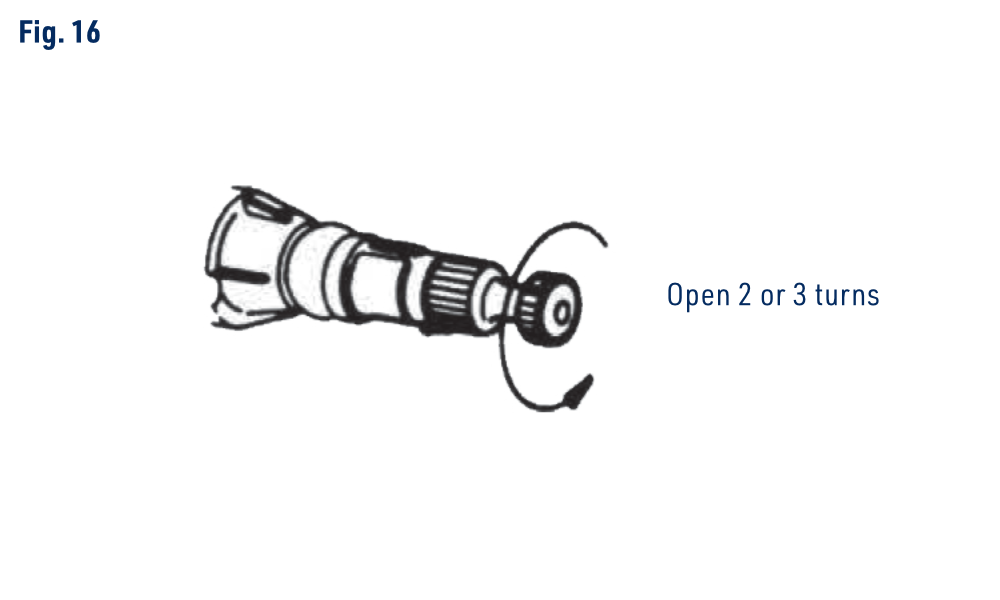
- Disconnect all glow power. Gently close the main needle without forcing the seat, then open it 2–3 turns. (Fig. 16)+(Fig. 17)
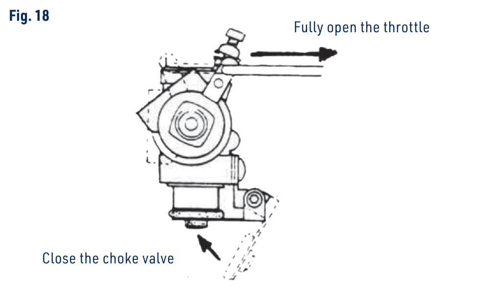
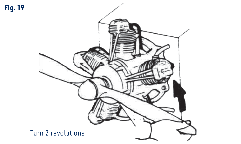
- With glow power still disconnected, fully open the throttle, close the choke and turn the propeller counterclockwise through two complete revolutions, viewed from the front. (Fig. 18)+(Fig. 19)
- If resistance indicates hydraulic locking, do not force the propeller. Remove all glow plugs, open the choke and gently turn clockwise to expel excess fuel. Refit the plugs only after clearing the cylinders.
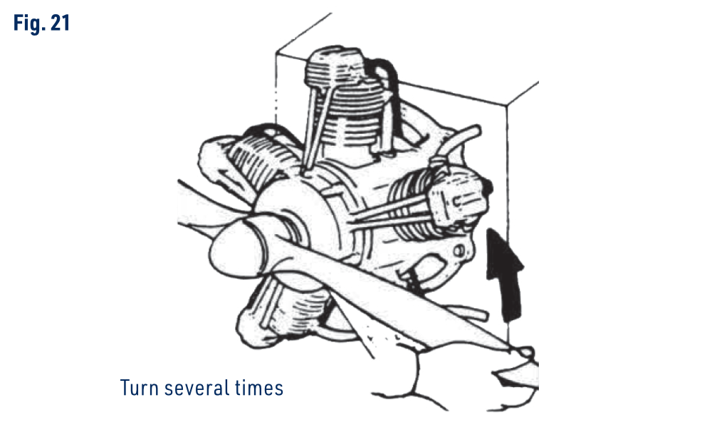
- Open the choke fully and turn the propeller counterclockwise several times to distribute fuel and check free rotation. Fuel-proof the surrounding structure: excess fuel may drip from the carburettor. (Fig. 21)
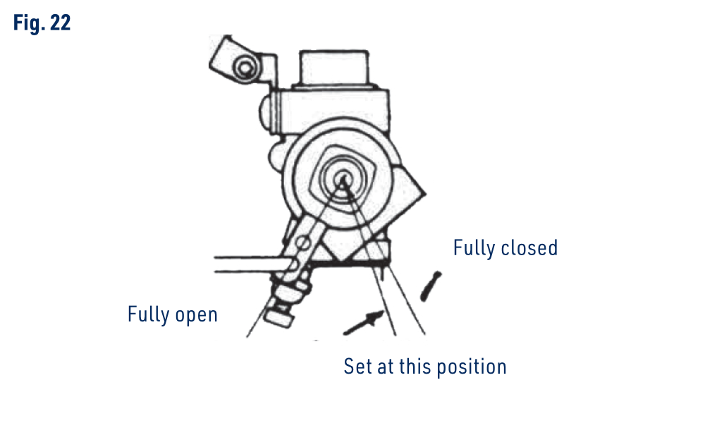
- Set approximately half throttle. Never start at full throttle. (Fig. 22)
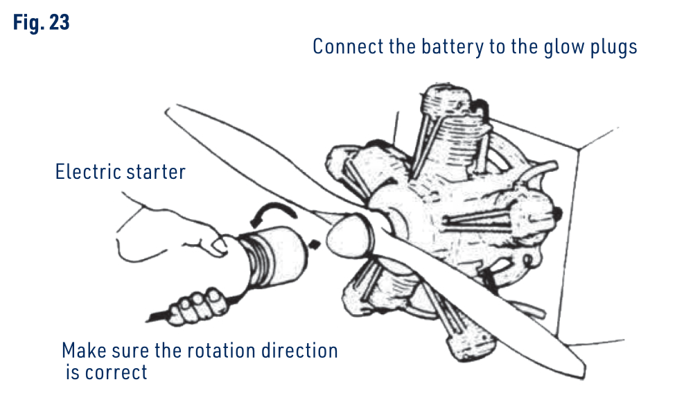
- For electric starting, check the starter’s direction, connect glow power and apply the starter with the choke open. (Fig. 23)
- For manual starting, use a starting stick or heavily padded glove. With glow power disconnected, check that the propeller is mounted horizontally when compression is first felt. Connect glow power, then swing from the middle of the right-hand blade counterclockwise, viewed from the front.
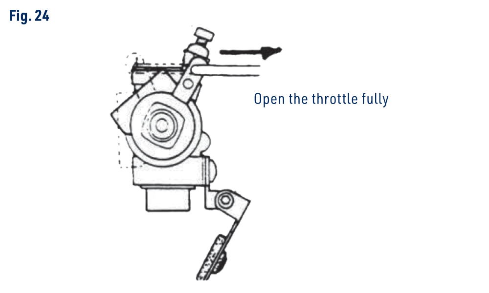
- After the engine starts, open the throttle fully and run for approximately 10 seconds at the initial rich needle setting. (Fig. 24)
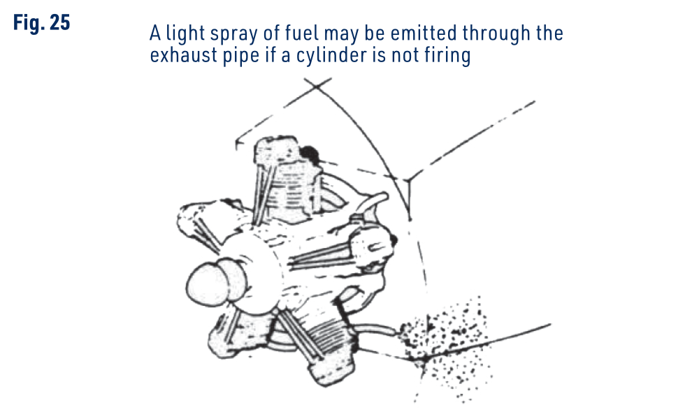
- Check that all five cylinders fire: white smoke should emerge evenly from every exhaust. A fine spray of fuel identifies a cylinder that is not firing. Without an onboard glow system, reduce to half throttle and reconnect glow power if a cylinder stops firing; speed rises when all cylinders resume firing. (Fig. 25)
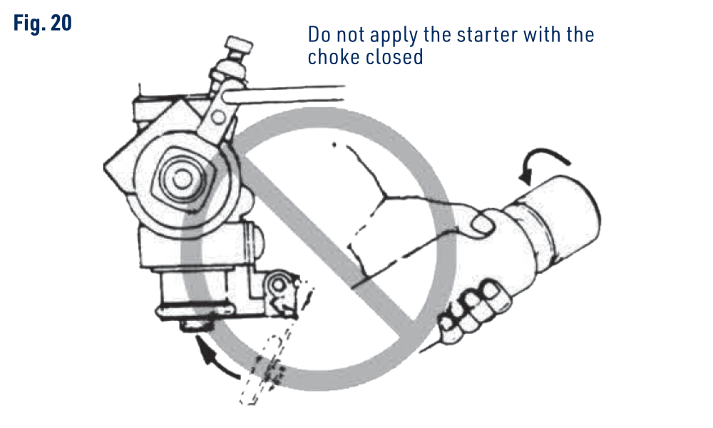
Never use the electric starter with the choke closed or force a hydraulically locked engine. Fuel or oil in a cylinder can cause severe mechanical damage. (Fig. 20)
The firing order is 1, 3, 5, 2, 4, viewed from behind the engine. (Fig. 2)
Adjusting the main needle
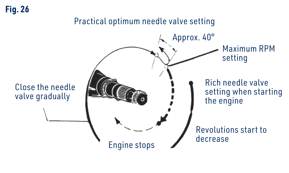
Disconnect external glow power before adjusting the high-speed mixture. Use small movements and pause after each adjustment; the engine responds with a delay, and abrupt changes can stop a new engine. The drawing places the practical running setting approximately 40° richer (farther open) than the maximum-speed position. Keep a richer setting during break-in.
Restarting a warm engine
To re-start the engine when warm, simply re-energise the plugs, and re-apply the starter with the throttle in the idling position. If the engine does not start, disconnect the battery from the glow plugs and re-prime by closing the choke valve while rotating the propeller twice with the throttle open. Initially, the high temperature inside the combustion chambers may turn the liquid fuel into gas and emit it through the exhaust pipes. Therefore, repeat the priming procedure once or twice only as needed, with glow power disconnected and hydraulic-lock checks repeated. Open the choke before applying the starter and use idle throttle for the restart.
Break-in procedure
Break-in allows new working parts to settle under operating temperature and load. The accurately manufactured KAVAN FS engines need a short, simple break-in that can be performed in the model. The original manual recommends an 18×10″ or 20×8″ propeller for break-in; the current catalogue specifies 18×8″. Confirm the approved propeller before running the engine.
Start the engine and run it for about 10 seconds with the main needle adjusted so the engine reaches approximately 6300 rpm, then open the needle valve to reduce speed to approximately 5000 rpm and run for 20 seconds at this cooler setting. Keep the throttle fully open, using only the needle valve to reduce speed.
Repeat this procedure, alternately running the engine fast and slow with the needle valve adjustments, while gradually extending the short period of high speed running until the engine has been run at least 10 minutes. Once this minimum 10 minute ground break-in has been achieved, continue break-in in the air.
For the first few flights, set the needle valve as rich as possible, consistent with necessary take off power and, if necessary, readjust the throttle trim on the transmitter to obtain a reliable idle at low stick, while retaining a separate trim/stop position that fully closes the carburettor.
After every flight, close the needle valve slightly until, after at least 10 flights, establish the normal running setting, slightly richer than peak speed. The carburettor can now be adjusted for optimum throttle performance with the Throttle Valve Adjustments. See Throttle adjustment.
Throttle adjustment
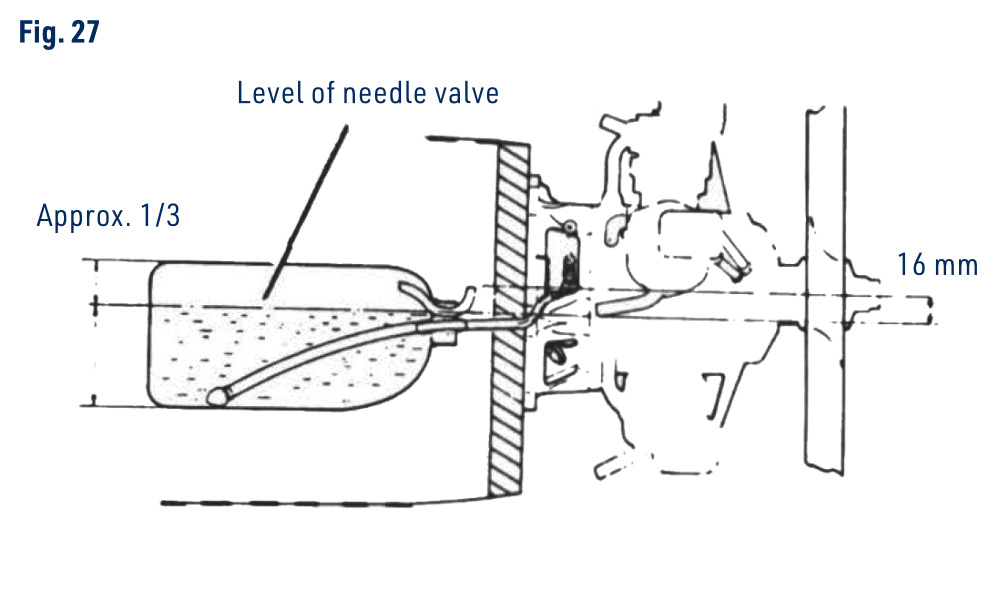
The carburettor of the FS400AR has been set at the factory for best performance with the fuel tank located in the normal position (close to the back of the engine and where the level of the needle valve is at 2/3 of the tank height). However, the settings may, in some cases, vary slightly because of variations of fuel and climate. Additionally, during engine break-in, the needle valve is set rich, thus, the carburettor cannot be expected to show the best response. Therefore, it is recommended that the FS400AR be run first with the throttle settings as set at factory. After proper engine break-in, check the operation of the throttle according to the Idle adjustment sequence below.
Only adjust controls when necessary.
Adjusting the idle mixture
The special carburettor fitted to the FS400AR controls the amount of fuel entering the engine according to the throttle opening and thus, maintains the correct mixture strength at all speeds from idle to full power. As previously explained, the idle mixture control screw is set at the factory, but should be rechecked after proper break-in:
- Start the engine, allow it to warm up, and then close the throttle. Allow engine to idle for a few moments and then reopen the throttle for full power. If engine performs well, continue to Pre-flight check. If engine hesitates, use the appropriate case below.
Any adjustments to engine should be done after engine is shut off.
- If the engine hesitates at this point, while emitting an amount of smoke before acceleration, the setting is too rich. If the setting is too rich, turn the Idle Mixture Control Screw clockwise to lessen the mixture. About 1/12 (30°) turn should correct the mixture setting.
- If the engine stops or is slow to pick up speed, without smoking, it is probable that the idling mixture is too lean. In this case, it will be necessary to turn the Mixture Control screw counter clockwise, approximately 1/12 (30°) turn should correct the mixture setting.
- If the revolutions increase but the engine still appears sluggish, it is possible that one of the cylinders has stopped firing. This can be detected by checking for exhaust from all pipes. The cease firing of the cylinder may be caused by the idling speed being set too low or the idling mixture either being too rich or too lean.
-
Normal safe idling speeds are in the 2000–2200 rpm range.
-
If the idle speed is set too low, reset the idle at a higher rpm using the throttle trim on the transmitter.
-
If the idle mixture is too rich, turn the idle mixture screw clockwise approximately 1/12 turn (30°).
-
If the idle mixture is too lean, turn the Idle Mixture Control Screw counterclockwise approximately 1/12 (30°) turn to correct the mixture setting.
Please note that a 5 cylinder, 4 cycle engine may appear to have a higher idling rpm than actual. It is strongly recommended to always use a tachometer when determining actual idling rpm.
Readjustment of the carburettor may be necessary whenever a change of glow plug or fuel is made.
Resetting the idle mixture
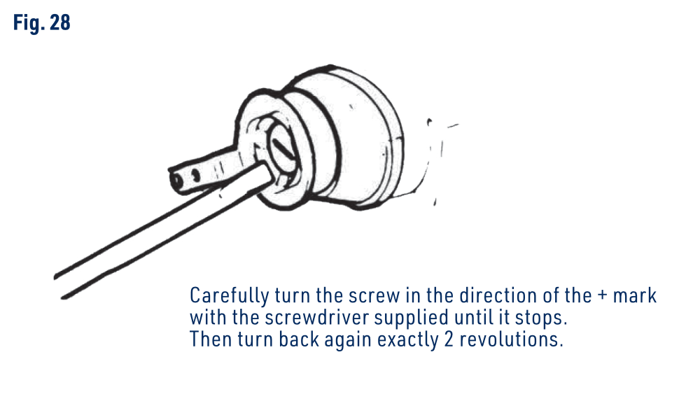
While carburettor adjustments are being made, it is possible that the Mixture Control Screw setting may be unintentionally changed. The pre-set setting can be found as following:
- Gently close the mixture screw against its seat without forcing it.
- Then turn the Screw a full 2 revolutions back.
If an onboard glow system is fitted, it should operate while you assess the idle mixture. Stop the engine and disconnect glow power before physically turning the screw.
Idle adjustment sequence
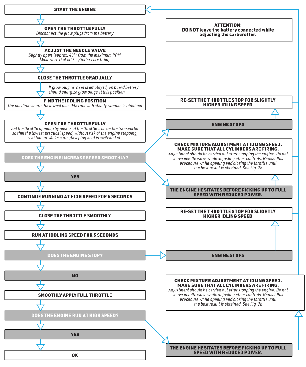
- Warm the engine, open the throttle fully, disconnect external glow power and set the main needle slightly rich of peak, approximately 40° open from peak. Check all five cylinders.
- Close the throttle gradually and find the lowest stable idle. If onboard glow is fitted, it should switch on at this setting; set idle with the system working as it will in flight.
- Open the throttle smoothly and check acceleration. If successful, run at high speed for 5 seconds, close smoothly and idle for 5 seconds, then reopen smoothly to full throttle.
- If it stops, first raise the idle stop/trim setting slightly and repeat. If it hesitates or lacks power, check all cylinders and the idle mixture. Stop the engine and disconnect glow power before turning the idle mixture screw; do not disturb the main needle while changing idle settings. Repeat until transitions are reliable.
Flight
Pre-flight check
- Ensure that all 5 cylinders are firing.
- As with a full size car or airplane engine, it is essential that the FS400AR is properly warmed before flight. Once started, allow the engine to run at full throttle for at least 10 seconds before releasing the model. NEVER attempt to takeoff immediately after the engine has been started.
Valve clearances
Valve clearances are correctly set before any KAVAN four stroke engine leaves the factory. In normal use, the valve clearances are not necessary to adjust until extended running time of the FS400AR. However, in case of loss of power after extended running time or when the related parts are replaced due to crash, etc., valve clearances should be checked and adjusted.
Additionally, we suggest that after proper break-in of the FS400AR carefully check to ensure that the valve clearances are correctly set.
ONLY check and re-set the valve clearances when the engine is cold.
Valve clearances that are too small may cause difficulty in starting your FS400AR because the valve will not be able to close properly, while valve clearances that are too great may cause loss of power because the valve will not be able to open sufficiently.
Checking valve clearances
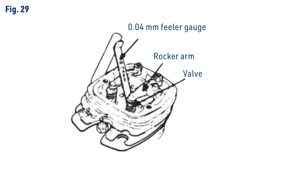
- Remove rocker cover by unscrewing the hex cap screws from the rocker box on the top of the cylinder head. Use the hex key supplied with your FS400AR to remove the hex cap screws.
- Turn propeller until compression is first felt. Once you feel compression, turn the propeller an additional 1/4 turn. At this position, both valves should now be closed.
- With the valves closed, the required valve clearance is 0.04–0.10 mm (0.0015–0.004″) measured between the valve stem and the rocker arm. Use the 0.04 mm and 0.10 mm feeler gauges to check clearances. (See Fig. 29) If the clearance is within range, recheck it as below. Otherwise read the following note and Setting valve clearances.
- It is important to ensure that the valve clearances are consistently within range. It is for this reason that all valve clearance checks are completed. Rotate propeller through compression stroke (approximately 2 rotations) and complete steps 2 & 3 again to ensure that tolerances are within range. Repeat the measurement to confirm consistency, then check both valves of every cylinder.
In most cases, the 0.04 mm feeler gauge should pass through the gap, while the 0.10 mm feeler gauge should not. However, if your engine is starting easily, and running satisfactorily, it may not need any adjustment, even if the valve clearance is below 0.04 mm, and up to 0.14 mm (can be tested by having 0.04 mm and 0.10 mm on top of one another).
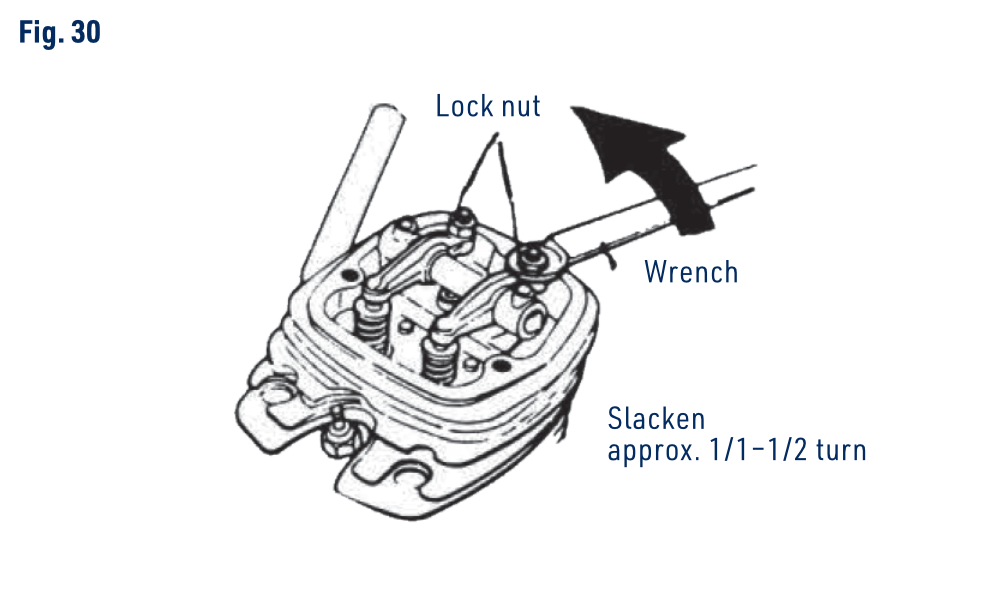
Setting valve clearances
If your engine is not starting easily and running satisfactorily and the gap is found to be less than 0.04 mm or greater than 0.10 mm, reset the valve clearance as follows:
- Using the special offset wrench included with your FS400AR, carefully loosen the locknut on the rocker arm about 1/4 to 1/2 turn. (See Fig. 30)
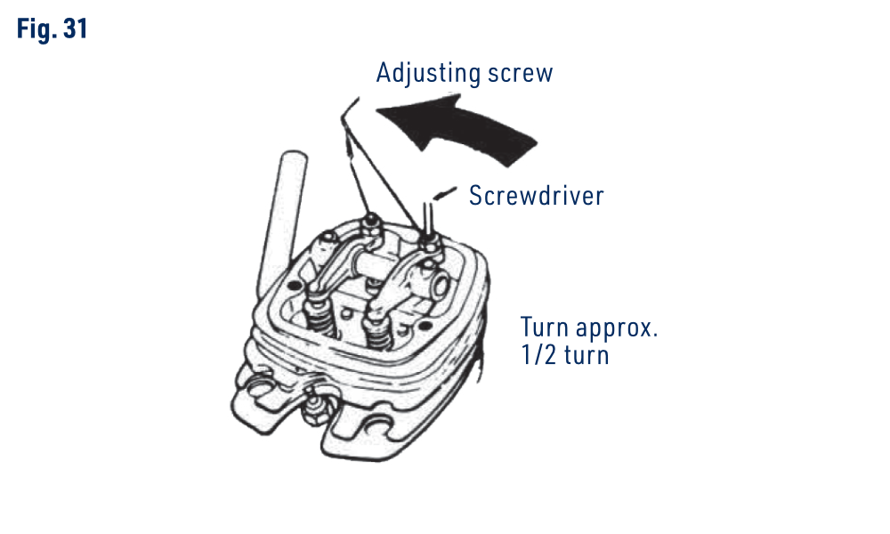
- Using the supplied screwdriver, turn the adjusting screw approximately 1/2 turn counter-clockwise to open gap with matched tool at screw head. (See Fig. 31)
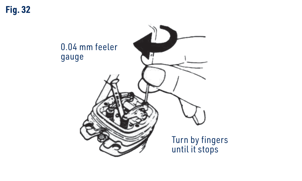
- Insert the 0.04 mm feeler gauge between the valve stem and the rocker arm. Using your fingers, turn the adjusting screw clockwise until it stops. (See Fig. 32)
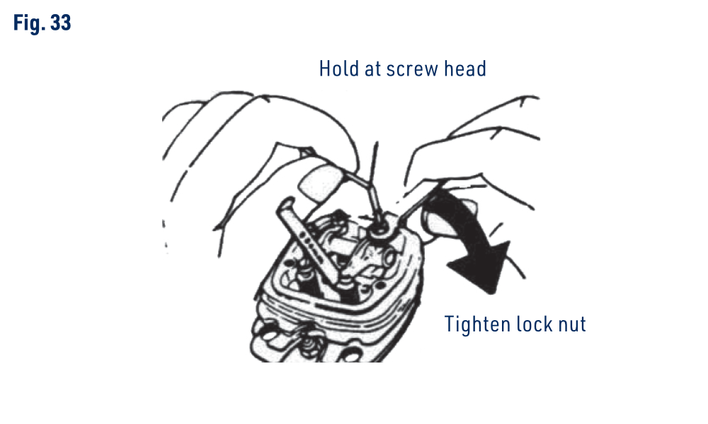
- While the 0.04 mm feeler gauge is still in place, use the screwdriver at screw head to hold adjusting screw in place, and tighten the locknut with special offset wrench. (See Fig. 33)
- Remove the 0.04 mm feeler gauge and re-check valve clearance by completing the Checking valve clearances procedure. If the valve clearance is correctly adjusted, check fit, and secure rocker cover in place.
Care and maintenance
To ensure that you obtain long life and peak performance from your engine, observe the following.
- Avoid running the engine under dusty conditions. If necessary, lay a sheet of plywood under and around the nose of the model when starting the FS400AR.
- Clean fuel is essential to keeping the carburettor clear and the engine running properly. To ensure clean fuel, following these steps:
- Rinse the fuel tank with methanol or clean fuel before installing it in the aircraft.
- Install a fuel filter between tank and carburettor.
- Install a fuel filter between fuel pump and tank.
- Check and clean filters often.
- Keep fuel can closed whenever not in use.
- Do not close the needle valve to too lean a setting. This lean setting will cause overheating and slowdown the engine performance.
- Hot combustion residues can also contribute to internal corrosion. Always set the main needle slightly richer than the peak-speed position.
- After every use, always clean the exterior of the engine with a clean cotton cloth. This will prevent oil and dirt from burning, and blackening the exterior of the FS400AR.
- If the FS400AR is not to be run for more than 2 months at any time, remove the glow plugs and rinse out the interior of the engine by injecting kerosene (not gasoline) into the cylinders through the glow plug holes and into the crankcase through the drain nipple. Once the kerosene is injected, slowly rotate the crankshaft to and fro, distributing the kerosene and dissolve residue throughout the engine. Once this has been accomplished, drain out the kerosene mixture by gently turning the propeller to help remove it from the cylinders. Keep glow power disconnected throughout, and do not apply an electric starter to a liquid-filled engine. Finally, add light machine oil through glow plug holes and drain nipple, rotating crankshaft slowly to distribute oil to all working parts.
Appendix
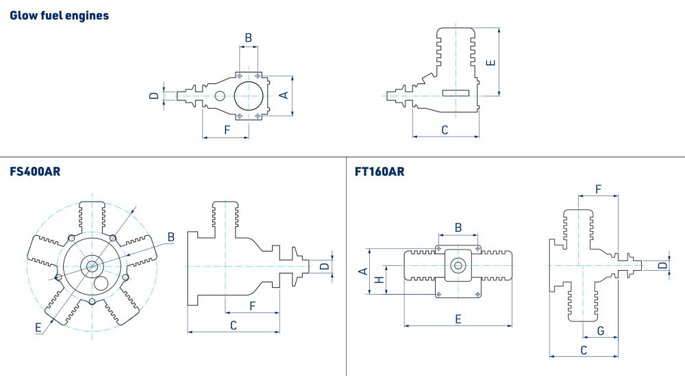
Dimensions (mm)
| A | B | C | D | E | F | G | H | |
|---|---|---|---|---|---|---|---|---|
| AP06A | 24 | 10 | 45 | M4 | 38.5 | 33 | ||
| AP09A | 30 | 11 | 58 | M5 | 43.5 | 41 | ||
| S15AII | 31.5 | 11 | 62 | M5 | 49.8 | 42.8 | ||
| S32AII | 38 | 15 | 74.9 | 1/4″–28 | 56.7 | 53.2 | ||
| S36AII | 38 | 15 | 74.9 | 1/4″–28 | 56.7 | 53.2 | ||
| S40AII | 44 | 17.5 | 84.3 | 1/4″–28 | 70.2 | 60.3 | ||
| S46AII | 44 | 17.5 | 85 | 1/4″–28 | 70 | 60 | ||
| S52AII | 44 | 17.5 | 85.8 | 1/4″–28 | 70.9 | 60.7 | ||
| S61AII | 52 | 25 | 97.8 | 5/16″–24 | 80.3 | 68.5 | ||
| S91A | 52 | 25 | 97.5 | 5/16″–24 | 84.7 | 67 | ||
| 108A | 58 | 25 | 105.3 | 3/8″–24 | 90 | 73.7 | ||
| 180AR | 68 | 36.5 | 133.7 | 3/8″–24 | 108 | 96.6 | ||
| FS-30AR | 36 | 14 | 64.7 | 1/4″–28 | 71 | 46.8 | ||
| FS-52AR | 44 | 17.5 | 80.6 | 1/4″–28 | 82.4 | 59.2 | ||
| FS-70AR | 50 | 21 | 89 | 5/16″–24 | 97.4 | 65.3 | ||
| FS-80AR | 50 | 21 | 90 | 5/16″–24 | 98.3 | 65.3 | ||
| FS-91AR | 52 | 25 | 90 | 5/16″–24 | 100 | 65.3 | ||
| FS-120AR | 58 | 25 | 106 | 5/16″–24 | 116.3 | 78.3 | ||
| FS-180AR | 58 | 25 | 111.8 | 3/8″–24 | 120 | 80.8 | ||
| FT-160AR | 80 | 68 | 120 | 3/8″–24 | 195.3 | 69.5 | 56.5 | 56.5 |
| FS-400AR | Ø122 | 160.5 | 3/8″–24 | Ø227 | 78 |
What to do in the event of a failure?
A guide to the warranty and post-warranty repairs
Warranty Conditions
Since this engine, which requires regular maintenance and care, is intended for operation by the modeller under conditions of much higher performance and load on the model than those to which toys in the ordinary sense of the word are exposed, we cannot assume (and it cannot be supposed) any guarantee relating to how long it takes before individual parts need to be replaced due to wear. Engine parts wear out and require replacement over time. If any part of the engine appears to be damaged, defective or incorrectly installed when the engine is new, before the first start, this part will be repaired or replaced free of charge. Engines are only protected by the warranty against manufacturing defects in material, workmanship or assembly when new (before use). If any part is found to be defective, incorrectly manufactured or incorrectly assembled during the statutory warranty period, it will be repaired or replaced by the importer free of charge. If you believe that the defect in material, workmanship or assembly was not apparent when the model was new and only became apparent after the product was used, then please contact KAVAN Europe s.r.o. (e-mail: info@kavanrc.com, tel. +420 446 260 133). We firmly believe in the quality of the products we sell and will do our utmost to ensure that you are satisfied with them.
Warranty Limitations
This warranty does not cover damage caused by improper or rough handling, negligence, accidents, water or excessive humidity, damage caused by chemicals, improper or negligent maintenance, neglect of maintenance, accidents, acts of God, unauthorised changes or modifications, or use of incorrect fuel. The warranty does not cover engine parts that are considered consumables (spark plugs, oils, etc.). KAVAN Europe s.r.o. does not cover the costs of transporting defective parts from the user.
Role of the Model Shop
The shop where you have purchased the engine is the first place where you should apply for a warranty repair or complaint. The dealer can help with identifying a possible defect and communicating with the importer. Only if, for some reason, it is not possible to use the services of the shop where the model has been purchased, contact KAVAN Europe s.r.o. directly.
Limitation of Liability
KAVAN Europe s.r.o. does not provide - nor can it be assumed to provide - any other warranties. KAVAN Europe s.r.o. is not responsible for any special, incidental or consequential damages arising from the assembly or use of its products, accessories or chemicals required for the use of its products. The moment the product is used or operated, the user assumes all liability arising therefrom. In no event shall KAVAN Europe s.r.o.‘s liability exceed the actual sales price paid for the product.
How to send products for warranty or non-warranty service?
First, email or call the importer or service centre. It often happens that a product may appear defective or malfunctioning simply because it has not been used correctly or requires only a simple adjustment. One email or phone call to our experienced service technicians can solve everything quickly and easily!
When sending your product for service check/repair, please remember to include:
- A copy of your proof of purchase
- A return address
- A telephone number where you can be reached during business hours
- Your email address
- A detailed description of the problem
Preparing Your Motor for Service
The guidelines below will help you save on postage and assist our service technicians in carrying out repairs and returning products.
- Clean the engine before shipping to avoid paying an additional cleaning fee.
- Do not send fuel, batteries, accumulators, chargers, glow plug clips, and glow plug heating devices, operating instructions or other accessories that you use when operating your engine (unless the service technician requests that you send one of these items). You will save on postage and avoid the risk of loss during transportation. KAVAN Europe s.r.o. is not responsible for the loss of unwanted accessories during transportation to the service or repair.
- When sending the product to the service, ensure the product is insured for the price corresponding to the newly purchased product. KAVAN Europe s.r.o. is in no way responsible for the loss of the product during transportation to the service.
- Pack the product thoroughly and securely in a hard cardboard box of appropriate dimensions. A freely moving engine in a large box can only cause additional damage.
- If possible, avoid using shredded paper or foam padding. If this cannot be avoided, place the padding or motor in a sealed plastic bag(s).
- Include all documentation needed to repair the motor, along with as detailed and concise a description of the fault or problem as possible.
- Include a telephone number where you can be reached during the business day and an email address so that the service technician can contact you with additional questions about the repair.
- Include a note with your address. It is surprising how often this is forgotten.