KAVAN FT160AR - Instruction manual
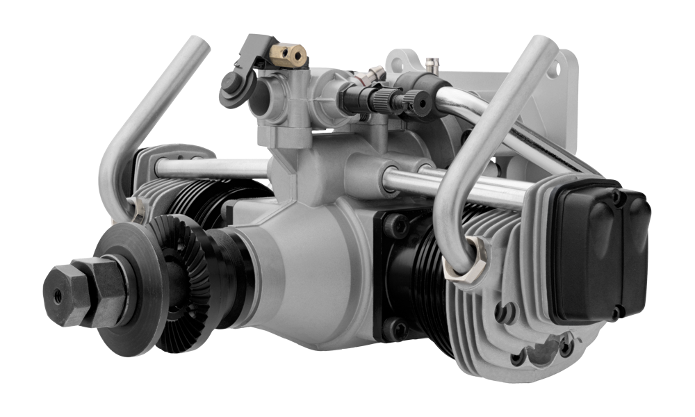
KAVAN FT160AR
Introduction
The KAVAN FT160AR is a flat-twin, overhead-valve four-stroke glow engine with piston rings, designed especially for scale aircraft. It has a twin-needle RC carburettor, a choke and an aluminium engine mount. The crankshaft propeller thread is 3/8″–24 UNF according to the current catalogue; use the supplied safety propeller locknut.
Before starting, read the entire manual and familiarise yourself with the controls. Follow the Safety notes and warnings.
Specifications
| Displacement | 2×12.8 cm³ (2×0.78 in³), 25.6 cm³ total |
|---|---|
| Bore | 26.5 mm (1.043″) |
| Stroke | 23.2 mm (0.913″) |
| Power | 2.2 kW at 8000 rpm |
| Operating speed | 2000–9000 rpm |
| Weight including muffler, as listed in the catalogue | 1265 g (44.6 oz.) |
| Fuel tank in the original manual | 360 ml |
Safety notes and warnings
The engine is not a toy. It is a powerful internal-combustion machine that can injure you or others if misused.
Before the first start, read the entire manual, familiarise yourself with the engine’s controls and features, and pay particular attention to the safety instructions.
Following these instructions helps ensure reliable and safe operation. You are responsible for operating your engine safely; always act thoughtfully and with care. Misuse or failure to observe safety precautions can cause serious injury.
- Do not allow especially small children and other spectators, who could be injured as a result of operating your engine, to come too close. The safe distance is at least 5–6 m (20 feet) away from the engine while it is running. No one should stand in line with the rotating propeller!
- Mount the engine securely in the plane, or on a proper engine test stand using high quality steel hex cap screws, washers and locknuts. Follow the mounting recommendations on the airplane‘s plan and/or instruction manual, or in the test stand described in the directions. DO NOT clamp this engine into a vice!
- Use the correct size propeller and follow the recommended mounting procedures. Follow this instruction manual, the building plan/kit instruction manual; ask an experienced modeller or skilled model shop personnel if in doubts.
- Install your propeller properly (looking from the cockpit of your model, the propeller of an engine installed in the nose rotates clockwise, looking from the front of the model it rotates counter clockwise). Use a proper wrench to tighten the propeller nut. Do NOT use pliers. Four stroke engines and large two stroke ones should use special safety locking propeller nuts.
- Never touch, or allow any object to come into contact with, the rotating propeller and do not crouch over the engine when it is running.
- Beware of the prop, protect your fingers. When hand cranking your engine, always us the „chicken stick“ (available in model hobby shops) or strong leather glove. Preferably, use an electric starter.
- After starting, adjust the main needle only from a safe position behind the rotating propeller.
- To stop your engine, adjust the throttle linkage so that the engine stops when the throttle stick and trim lever on the transmitter are fully retarded. Alternatively, the engine may be stopped by cutting off the fuel supply. Never try to stop the engine physically.
- Discard any propeller which has become split, cracked, nicked or otherwise rendered unsafe. Never attempt to repair such a propeller: destroy it. Do not modify a propeller in any way. Also, check the tightness of all the screws and nuts regularly and frequently
- If you have to carry the model to the take-off point with the engine running, be especially cautious. Keep the propeller pointed away from you and walk well clear of spectators.
- Do not fly your model near or under power lines.
Safety tips
- The wearing of safety glasses is strongly recommended.
- Do not start your engine in an area containing loose gravel or sand. The propeller may throw such material in your face and eyes and cause injury.
- Take care that loose clothing (ties, shirt sleeves, scarves, etc.) do not come into contact with the propeller. Do not carry loose objects (such as pencils, screwdrivers, etc.) in a shirt pocket from where they could fall through the propeller arc.
- Take care that the glow plug clip or battery leads do not come into contact with the propeller.
- If you install a spinner, make sure that the slots for the propeller blades do not touch the blade roots and weaken them.
Warnings
- Model engine fuel is poisonous. Do not allow it to come into contact with the eyes or mouth. Always store it in a clearly marked container and in a cool, dark place out of the reach of children.
- Model engine fuel is also highly flammable. Keep it away from open flame, excessive heat, sources of sparks, or anything else which might ignite it. Do not smoke or allow anyone else to smoke, near to it.
- The engine and exhaust pipes become very hot. Do not touch them before they cool; the cylinder heads and exhausts in particular can cause serious burns.
- Never operate your engine in an enclosed space. Model engines, like automobile engines, exhaust deadly carbon-monoxide. Run your engine only in an open area.
- Remember: Operating any model requires experience and constant attention to safety rules. Model airplanes, boats or cars have a lot of energy that can cause serious personal injury or significant property damage.
Always proceed with caution! If you are a beginner, ask for help and advice from an experienced modeller! Before trying to start the engine for the first time, carefully read the instructions and safety rules!
Main section
Engine installation
Use the strong square aluminium-alloy mount supplied with the FT160AR to bolt the engine securely to the firewall. Install the carburettor below the crankcase to preserve the scale appearance.
The main needle and throttle lever can exchange sides; the choke rod can be fitted on either side. Decide their positions before installing the engine in the fuselage.
Fuel tank
The suggested full tank size is 360 ml or 12-1/2 oz. This will give approximately 12 minutes running time at full power, or about 15–17 minutes when some part throttle operation is included. Fuel consumption also depends, of course, on the size of propeller used.
The ideal fuel tank location is with the top of the tank 5–10 mm (1/4–3/8‘‘) above the needle valve. However, model design will usually require the tank to be located higher than this and there should be no trouble with such a tank location provided that you do not pursue spectacular aerobatics flight. If the tank is located high, fuel will flow into the carburettor when the tank is full. Therefore, pinch the fuel line with a clip, when the engine is not running, to prevent flooding and loss of fuel.
Fuel
Use good-quality model glow-engine fuel. The FT160 engine runs on standard commercially available model glow engine fuel. Fuels containing castor oil and/or synthetic lubricants are acceptable but, for the best performance and reliability, a fuel containing 5-15% nitromethane (KAV54.010.5 / KAV54.011.5 / KAV54.012.5) is recommended.
For consistent performance and long life of the engine, it is advisable to use good quality fuel containing MORE THAN 16% LUBRICANT until a total of one to two hours running time has been accumulated including the running-in period. Generally, the fuel containing a lower lubricant content improves the running characteristics of a four stroke engine slightly, but it may also shorten engine life.
Glow plugs
A four-stroke engine fires every fourth piston stroke, rather than every second stroke, so a conventional two-stroke plug may be unsuitable. The original manual recommends KAVAN PRO KF or O.S. MAX Type F. Use matching four-stroke plugs in both cylinders and follow their rated heating voltage.
Choosing a propeller
Choose the propeller for the model’s size, weight and intended flying style, then confirm the best size by practical trials. The original ranges and catalogue recommendations are:
| Use | Propeller diameter × pitch |
|---|---|
| Starting range | 14×(9–11)″; 15×(8–10)″; 16×(6–8)″; 17×6″; 18×6″ |
| Break-in | 16×8″ |
| Sport and aerobatics | 14×9″; 14×11″; 15×8″; 15×10″ |
| Scale models | 17×6″; 18×6″ |
Use only well-balanced, undamaged propellers. Imbalance causes vibration and power loss. Keep your face and body clear of the entire propeller arc when starting or adjusting the main needle; this engine can drive large propellers.
Propeller installation
A loose propeller nut can allow the propeller to slip or fly off, particularly if an excessively lean mixture or heavy load causes knocking. Use the supplied safety locknut assembly and tighten the main nut securely.
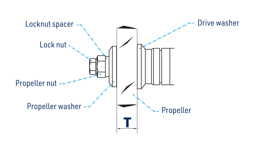
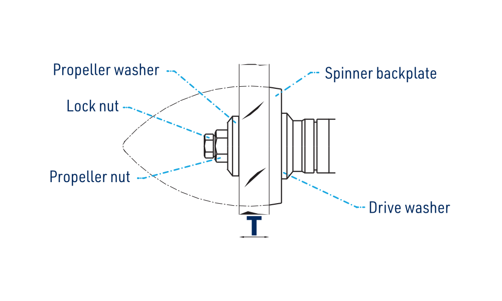
- Ream the centre hole to Ø12 mm (0.472″) and balance the propeller.
- Fit the propeller, washer and sleeve-nut to the shaft. Tighten the sleeve-nut firmly with the supplied 17mm wrench.
- Check dimension „T“ in the drawings: the clamped thickness includes the spinner backplate if fitted. Where a locknut spacer is supplied, use it for T = 14.5–18 mm (0.571–0.709″); the original manual specifies no spacer for T = 18–22.5 mm (0.709–0.886″). Check the actual assembly and secure engagement of both nuts.
- Fit the safety locknut and tighten it firmly with a 14mm wrench, without excessive force.
- Check tightness before every start. Wood can shrink over time or become compressed by the serrated drive washer. Loosen the locknut before retightening the main nut, then secure the locknut again.
Glow-plug wiring
Connect the supplied glow leads and clips to both plugs. Fasten the ground-lead ring terminal to the engine mount with an engine fixing screw.
- Keep the insulated leads and clips clear of the cylinder heads, cooling fins and propeller.
- Route wiring away from the fuel tank to prevent a short circuit from starting a fire.
- Use a suitable high-capacity glow supply for both plugs simultaneously. The original manual gives a rechargeable lead-acid cell of approximately 20 Ah as an example; its capacity does not define a safe plug voltage. Use voltage regulation or individual plug circuits appropriate to the plugs, and never apply a lead-acid cell directly unless its voltage is suitable.
- Use sufficiently thick leads for the several amperes required, preventing excessive voltage drop. The English PDF omits the exact current; the Czech and German sources say several amperes, without specifying a value.
Do not use a single shared rheostat to drop the voltage for both plugs. If one lead disconnects or one filament fails, the remaining plug may receive excessive voltage. The original manual gives a separate battery and rheostat for each plug as an alternative. Keep glow power disconnected during priming and mechanical adjustments.
Carburettor adjustment
Controls
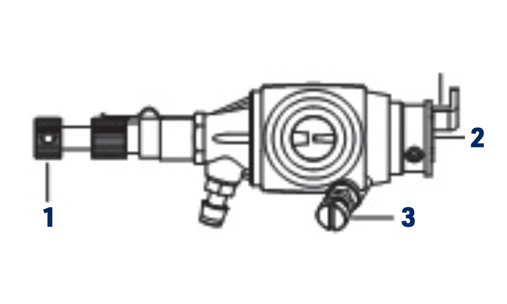
- Main needle: sets the basic air/fuel mixture at full throttle; lower-speed mixture then follows the carburettor’s metering system.
- Idle mixture needle: controls fuel delivery at low speed and during throttle transitions. Start with the factory setting and change it only if necessary.
- Idle stop screw: limits the throttle barrel’s travel.
Throttle servo
With the transmitter throttle trim fully lowered, set the linkage and servo travel so that full stick fully opens the barrel and low stick completely closes it. Raise the trim to obtain a reliable idle. Lowering it again must stop the engine.
Restoring the initial idle mixture setting
With the engine stopped, glow power disconnected and the fuel supply disconnected, use a short, clean, fuel-free tube on the carburettor fuel inlet to check gentle airflow. The legacy procedure uses mouth-blown air; use a clean hand-operated air bulb instead to avoid contact with poisonous fuel. Do not use compressed air.
- Initially close the throttle barrel to an opening no wider than a modeller’s pin, approximately 0.7 mm.
- Fit the clean test tube and open the main needle 1½ turns from gently closed.
- Following the original procedure, close the barrel completely for the airflow check. Apply gentle air and adjust the idle mixture needle until air just begins to pass.
- Open the idle mixture needle a further 1/2 turn.
- Continue the airflow check while opening the barrel. Airflow should change rapidly at about 15° from idle.
- Do not make the mixture excessively rich merely to lower idle speed. Close the throttle barrel slightly farther instead, then repeat the idle mixture adjustment.
Starting
Secure the model and keep people clear of the propeller. An electric starter is preferred; manual starting is described separately below. Rotation is counterclockwise when viewed from the front.
Disconnect both glow plugs from power before priming. Never use an electric starter with the choke closed. Initially turn the propeller no more than 2 revolutions with the choke closed: excess fuel can hydraulically lock and damage the engine. If it will not turn freely, do not force it or apply the starter; disconnect glow power, remove the plugs and drain excess fuel before trying again.
Electric starting
- With glow power disconnected, open the throttle fully. Gently close the main needle without forcing its seat, then open it 3½ turns.
- Close the choke and turn the propeller counterclockwise 2 revolutions by hand, with the throttle fully open.
- Open the choke and immediately turn the propeller counterclockwise several times to distribute fuel and check free rotation.
- Set the throttle about 1/3 open. Connect both glow plugs and apply the starter with the choke open.
- When the engine starts, open the throttle fully and run initially for about 20 seconds at the original rich needle setting. If excessive richness slows the engine, close the main needle gradually by about 1/4–1/2 turn.
- Disconnect glow power, then close the main needle gradually to increase speed. Pause between adjustments; abrupt changes can stop a new, insufficiently run-in engine. Keep the richer break-in setting until running-in is complete.
Manual starting
Use a starting stick or heavily padded leather glove. Never use a bare hand.
- With glow power disconnected, check that the propeller is mounted horizontally at the first point of compression when turned counterclockwise.
- Open the throttle fully and set the main needle 3½ turns open from gently closed.
- Close the choke and turn the propeller counterclockwise 2 revolutions.
- Open the choke and turn the propeller counterclockwise several times to distribute fuel. Check that the engine turns freely.
- Set the throttle about 1/3 open and turn counterclockwise until compression is felt.
- Connect both glow plugs, then swing the propeller sharply counterclockwise from the centre of the right-hand blade, viewed from the front. If it starts and stops, check the fuel supply. Disconnect glow power before repeating the priming steps.
- After starting, open the throttle fully and run for about 20 seconds at the original needle setting. If excessively rich, close the main needle gradually by about 1/4–1/2 turn.
- Disconnect glow power before gradually adjusting the main needle. Avoid abrupt adjustments, especially with a new engine.
Warm restart
Re-energise both plugs and try the starter or manual flick with the throttle at idle. If it will not restart, disconnect glow power, fully open the throttle, close the choke and turn the propeller twice. Hot combustion chambers can vaporise the fuel and discharge it through the exhausts; repeat priming once or twice only if needed. Check for hydraulic locking, reopen the choke and return to idle before reconnecting glow power and restarting.
Excess fuel may drip from the carburettor when the choke reopens. Provide a drain hole in the bottom of the engine bay or cowling and protect surrounding structure with fuel-proof paint.
Break-in
- Install the engine and a suitable propeller; the catalogue recommends 16×8″ for break-in. Run for about 10 seconds at 6000–6500 rpm, set with the main needle.
- Open the main needle to reduce speed to approximately 4000 rpm and run for 20 seconds at this cooler setting. Keep the throttle fully open; control speed with the main needle only.
- Repeat these high/low cycles, gradually lengthening the high-speed periods, until at least 20 minutes of running have accumulated.
- If a tachometer is unavailable, exhaust smoke provides a guide: dense grey smoke becomes less visible as the main needle is closed.
- After the initial 20 minutes on the ground, continue break-in in flight. Use the richest setting that still provides sufficient take-off power. Set trim for a reliable idle at low stick while retaining the separate trim/stop position that fully closes the carburettor.
- Close the main needle slightly on successive flights until normal operation is reached after approximately 10 flights. Retain a setting slightly richer than peak speed, as shown by the idle-adjustment diagram, then optimise throttle response.
Idle adjustment sequence
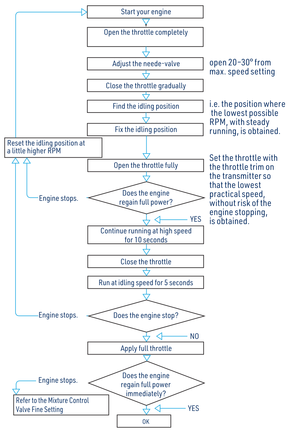
- Start and warm the engine, open the throttle fully and disconnect external glow power. Set the main needle 20–30° farther open than the maximum-speed position.
- Close the throttle gradually to find the lowest steady speed. Set the transmitter trim for the lowest practical idle without stopping.
- Open the throttle fully. If the engine stops, raise the idle setting slightly and repeat.
- Once full power returns, run at high speed for 10 seconds, close the throttle and idle for 5 seconds.
- Apply full throttle again. If it stops or does not regain full power promptly, follow Fine idle mixture adjustment, then repeat the sequence until transitions are reliable.
Fine idle mixture adjustment
Start the engine, gradually close the throttle and set idle. Hold the model securely and slowly raise its nose from level. Adjust from behind the propeller; stop the engine and disconnect glow power before touching a control that cannot be reached safely.
- If speed rises, close the idle mixture needle slightly and repeat until speed remains unchanged when the nose is raised.
- If the engine runs irregularly or stops, open the idle mixture needle slightly and repeat.
The main and idle mixture settings affect each other. A substantial change to either may require fine adjustment of the other.
Exhaust-pipe adjustment
Loosen the pipe-to-head nut with the supplied spanner and set the exhaust direction to suit the installation. Flexible exhaust extensions of 12 cm or 24 cm are mentioned in the original manual; ask a model specialist for a compatible part.
Lubrication and breather
Oil in the fuel lubricates the engine automatically. Fit silicone tubing with an internal Ø2.5–3 mm to the brass breather nipple under the timing case and route escaping oil outside the model. Never block or restrict this nipple.
Valve clearances
Valve clearances are set at the factory and seldom need adjustment. Check them after prolonged running if power falls, or after dismantling or repair following a crash.
Check and adjust valve clearances only with the engine cold and glow power disconnected.
Checking the clearances
- Use the supplied hex key to remove the two socket-head screws and rocker cover from each cylinder head.
- Turn the propeller 2 revolutions counterclockwise and observe both valves. From the inlet valve finishing its movement to the exhaust valve beginning to open, the propeller travels approximately 260° with both valves closed. From the exhaust opening point, turn clockwise approximately 130° to place the piston at top dead centre on compression.
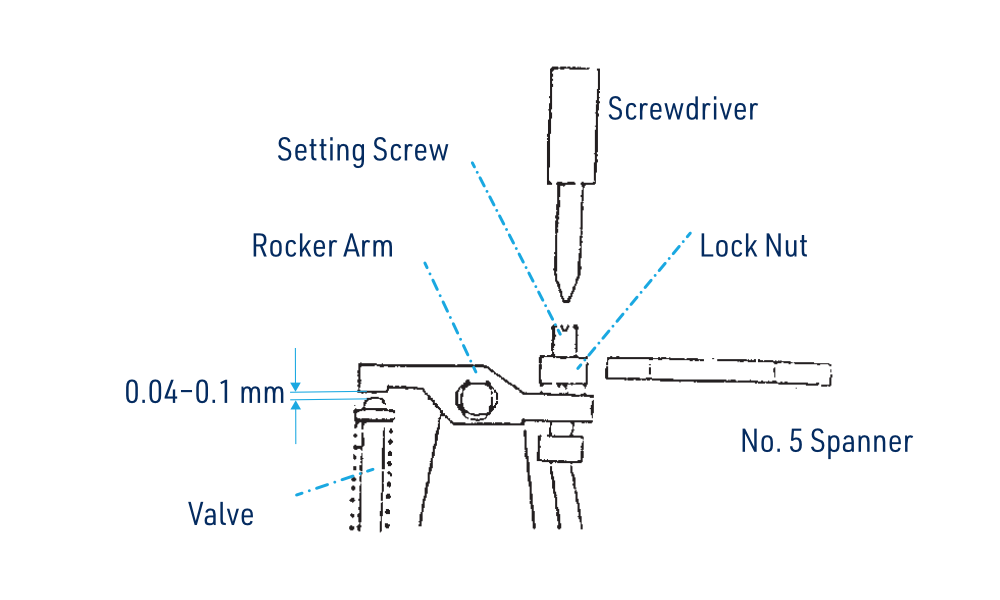
- Measure between the valve stem and rocker arm. The required clearance is 0.04–0.10 mm (0.0015–0.004″). A 0.04mm feeler should pass; a 0.10mm feeler should not.
Adjusting the clearances
- Carefully loosen the rocker-arm locknut with the supplied No. 5 spanner.
- Turn the adjusting screw approximately 1/2 turn counterclockwise to open the gap.
- Insert the 0.04mm feeler between the valve stem and rocker arm. Turn the screw gently clockwise with a screwdriver until it just contacts the gauge.
- Hold the adjusting screw still with the screwdriver and retighten the locknut.
- Remove the 0.04mm feeler, rotate the propeller exactly two revolutions and recheck. Check and adjust the other valve if necessary, then refit the rocker cover.
- Check the other cylinder and adjust it in the same way if required.
Appendix
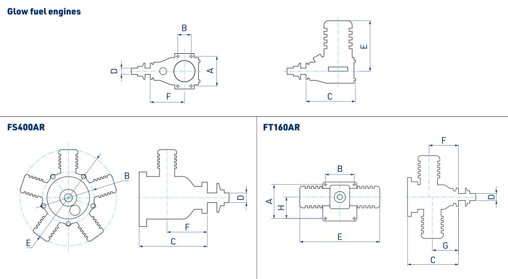
Dimensions (mm)
| A | B | C | D | E | F | G | H | |
|---|---|---|---|---|---|---|---|---|
| AP06A | 24 | 10 | 45 | M4 | 38.5 | 33 | ||
| AP09A | 30 | 11 | 58 | M5 | 43.5 | 41 | ||
| S15AII | 31.5 | 11 | 62 | M5 | 49.8 | 42.8 | ||
| S32AII | 38 | 15 | 74.9 | 1/4″–28 | 56.7 | 53.2 | ||
| S36AII | 38 | 15 | 74.9 | 1/4″–28 | 56.7 | 53.2 | ||
| S40AII | 44 | 17.5 | 84.3 | 1/4″–28 | 70.2 | 60.3 | ||
| S46AII | 44 | 17.5 | 85 | 1/4″–28 | 70 | 60 | ||
| S52AII | 44 | 17.5 | 85.8 | 1/4″–28 | 70.9 | 60.7 | ||
| S61AII | 52 | 25 | 97.8 | 5/16″–24 | 80.3 | 68.5 | ||
| S91A | 52 | 25 | 97.5 | 5/16″–24 | 84.7 | 67 | ||
| 108A | 58 | 25 | 105.3 | 3/8″–24 | 90 | 73.7 | ||
| 180AR | 68 | 36.5 | 133.7 | 3/8″–24 | 108 | 96.6 | ||
| FS-30AR | 36 | 14 | 64.7 | 1/4″–28 | 71 | 46.8 | ||
| FS-52AR | 44 | 17.5 | 80.6 | 1/4″–28 | 82.4 | 59.2 | ||
| FS-70AR | 50 | 21 | 89 | 5/16″–24 | 97.4 | 65.3 | ||
| FS-80AR | 50 | 21 | 90 | 5/16″–24 | 98.3 | 65.3 | ||
| FS-91AR | 52 | 25 | 90 | 5/16″–24 | 100 | 65.3 | ||
| FS-120AR | 58 | 25 | 106 | 5/16″–24 | 116.3 | 78.3 | ||
| FS-180AR | 58 | 25 | 111.8 | 3/8″–24 | 120 | 80.8 | ||
| FT-160AR | 80 | 68 | 120 | 3/8″–24 | 195.3 | 69.5 | 56.5 | 56.5 |
| FS-400AR | Ø122 | 160.5 | 3/8″–24 | Ø227 | 78 |
What to do in the event of a failure?
A guide to the warranty and post-warranty repairs
Warranty Conditions
Since this engine, which requires regular maintenance and care, is intended for operation by the modeller under conditions of much higher performance and load on the model than those to which toys in the ordinary sense of the word are exposed, we cannot assume (and it cannot be supposed) any guarantee relating to how long it takes before individual parts need to be replaced due to wear. Engine parts wear out and require replacement over time. If any part of the engine appears to be damaged, defective or incorrectly installed when the engine is new, before the first start, this part will be repaired or replaced free of charge. Engines are only protected by the warranty against manufacturing defects in material, workmanship or assembly when new (before use). If any part is found to be defective, incorrectly manufactured or incorrectly assembled during the statutory warranty period, it will be repaired or replaced by the importer free of charge. If you believe that the defect in material, workmanship or assembly was not apparent when the model was new and only became apparent after the product was used, then please contact KAVAN Europe s.r.o. (e-mail: info@kavanrc.com, tel. +420 446 260 133). We firmly believe in the quality of the products we sell and will do our utmost to ensure that you are satisfied with them.
Warranty Limitations
This warranty does not cover damage caused by improper or rough handling, negligence, accidents, water or excessive humidity, damage caused by chemicals, improper or negligent maintenance, neglect of maintenance, accidents, acts of God, unauthorised changes or modifications, or use of incorrect fuel. The warranty does not cover engine parts that are considered consumables (spark plugs, oils, etc.). KAVAN Europe s.r.o. does not cover the costs of transporting defective parts from the user.
Role of the Model Shop
The shop where you have purchased the engine is the first place where you should apply for a warranty repair or complaint. The dealer can help with identifying a possible defect and communicating with the importer. Only if, for some reason, it is not possible to use the services of the shop where the model has been purchased, contact KAVAN Europe s.r.o. directly.
Limitation of Liability
KAVAN Europe s.r.o. does not provide - nor can it be assumed to provide - any other warranties. KAVAN Europe s.r.o. is not responsible for any special, incidental or consequential damages arising from the assembly or use of its products, accessories or chemicals required for the use of its products. The moment the product is used or operated, the user assumes all liability arising therefrom. In no event shall KAVAN Europe s.r.o.‘s liability exceed the actual sales price paid for the product.
How to send products for warranty or non-warranty service?
First, email or call the importer or service centre. It often happens that a product may appear defective or malfunctioning simply because it has not been used correctly or requires only a simple adjustment. One email or phone call to our experienced service technicians can solve everything quickly and easily!
When sending your product for service check/repair, please remember to include:
- A copy of your proof of purchase
- A return address
- A telephone number where you can be reached during business hours
- Your email address
- A detailed description of the problem
Preparing Your Motor for Service
The guidelines below will help you save on postage and assist our service technicians in carrying out repairs and returning products.
- Clean the engine before shipping to avoid paying an additional cleaning fee.
- Do not send fuel, batteries, accumulators, chargers, glow plug clips, and glow plug heating devices, operating instructions or other accessories that you use when operating your engine (unless the service technician requests that you send one of these items). You will save on postage and avoid the risk of loss during transportation. KAVAN Europe s.r.o. is not responsible for the loss of unwanted accessories during transportation to the service or repair.
- When sending the product to the service, ensure the product is insured for the price corresponding to the newly purchased product. KAVAN Europe s.r.o. is in no way responsible for the loss of the product during transportation to the service.
- Pack the product thoroughly and securely in a hard cardboard box of appropriate dimensions. A freely moving engine in a large box can only cause additional damage.
- If possible, avoid using shredded paper or foam padding. If this cannot be avoided, place the padding or motor in a sealed plastic bag(s).
- Include all documentation needed to repair the motor, along with as detailed and concise a description of the fault or problem as possible.
- Include a telephone number where you can be reached during the business day and an email address so that the service technician can contact you with additional questions about the repair.
- Include a note with your address. It is surprising how often this is forgotten.