KAVAN S15–S180A/R, FS30–FS180AR - Instruction manual
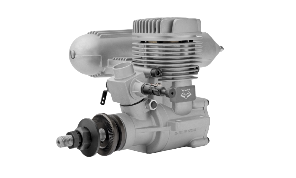
Two-stroke engines
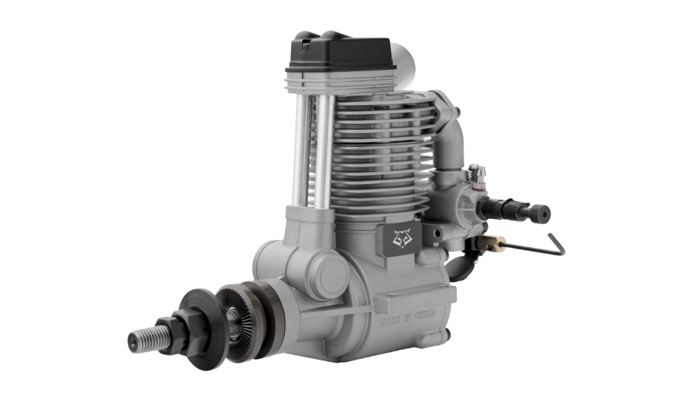
Four-stroke engines
Introduction
KAVAN glow engines are designed for sport, aerobatic and scale model aircraft. This manual covers the single-cylinder S-series two-stroke engines, including ABC and piston-ring designs, and the single-cylinder FS-series overhead-valve four-stroke engines. Correct installation, running-in and regular maintenance are essential for reliable operation.
Before starting, read the entire manual and familiarise yourself with the controls. Follow the Safety notes and warnings.
Specifications
The tables use current catalogue specifications where available. S32AII retains the legacy wiki data. Propeller sizes are diameter × pitch in inches; choose a balanced propeller suited to the model and intended flying style.
Two-stroke engines
| Model | AP06A | AP09A | S15AII | S32AII | S36AII | S40AII | S46AII | S52AII | S61AII | S91A | 108A | 180AR |
|---|---|---|---|---|---|---|---|---|---|---|---|---|
| Displacement (cm³) | 0.994 | 1.47 | 2.49 | 5.3 | 5.81 | 6.47 | 7.45 | 8.47 | 9.95 | 14.95 | 17.22 | 29.82 |
| Power (kW) | 0.20 | 0.35 | 0.51 | 0.86 | 1.02 | 1.20 | 1.34 | 1.47 | 1.68 | 2.30 | 2.40 | 4.10 |
| At speed (rpm) | 18 000 | 16 500 | 16 500 | 17 500 | 17 500 | 17 500 | 17 500 | 17 500 | 17 500 | 16 000 | 17 000 | 7600 |
| Bore (mm) | 11.25 | 12.5 | 15.2 | 19.5 | 20.5 | 20.5 | 22 | 22.4 | 24 | 27.7 | 28.5 | 35 |
| Stroke (mm) | 10 | 12 | 13.7 | 17.6 | 17.6 | 19.6 | 19.6 | 21.5 | 22 | 24.8 | 27 | 31 |
| Operating speed (rpm) | 5000–25 000 | 3000–17 000 | 3000–17 000 | 2000–18 000 | 2000–18 000 | 2000–17 500 | 2000–17 500 | 2000–17 500 | 2000–18 000 | 2000–17 000 | 2000–17 500 | 1800–7800 |
| Weight (g) | 55 | 165 | 164 | 333 | 335 | 385 | 472 | 397 | 552 | 595 | 676 | 1250 |
| Fuel tank (ml) | 20–55 | 50–60 | 60–120 | 150–230 | 150–230 | 200–250 | 200–300 | 250–350 | 250–350 | 400–500 | 400–500 | 500–700 |
Four-stroke engines
| Model | FS30AR | FS52AR | FS70AR | FS80AR | FS91AR | FS120AR | FS180AR | FT160AR | FS400AR |
|---|---|---|---|---|---|---|---|---|---|
| Displacement (cm³) | 5.0 | 8.56 | 11.5 | 12.8 | 14.95 | 19.96 | 29.52 | 2×12.8 | 5×12.8 |
| Power (kW) | 0.40 | 0.71 | 1.05 | 1.11 | 1.30 | 1.60 | 2.30 | 2.20 | 5.55 |
| At speed (rpm) | 9500 | 9500 | 11 000 | 11 000 | 10 500 | 10 500 | 8800 | 8000 | 7250 |
| Bore (mm) | 19.7 | 23 | 25.8 | 26.5 | 27.7 | 30.4 | 36 | 26.5 | 26.5 |
| Stroke (mm) | 16.4 | 20.6 | 22 | 23.2 | 24.8 | 27.5 | 29 | 23.2 | 23.2 |
| Operating speed (rpm) | 2500–10 000 | 2000–10 000 | 2000–11 000 | 2000–11 500 | 2000–11 000 | 2000–11 000 | 2000–9500 | 2000–9000 | 1800–9000 |
| Weight (g) | 275 | 455 | 606 | 620 | 640 | 888 | 1050 | 1265 | 2800 |
| Fuel tank (ml) | 100–170 | 200–250 | 300–350 | 300–350 | 350–400 | 450–500 | 500–600 | 360 | 500–600 |
Weights are catalogue values including the standard muffler where supplied; FS400AR includes its mount. See the dedicated manuals for the multi-cylinder engines.
Propeller selection
| Model | Break-in or basic recommendation | Sport and aerobatics | Scale or high-wing models |
|---|---|---|---|
| AP06A | 5.7×3″ | — | — |
| AP09A | 7×4″ | 7×3″ | — |
| S15AII | 8×4″ | 8×4″; 8×5″ | 8×4″ |
| S32AII | 10×5″ | 9×(6–7)″ | 11×(4–5)″ |
| S36AII | 10×6″ | 9×6″; 9×7″; 10×6″ | 11×4″; 11×5″ |
| S40AII | 10×6″ | 10.5×6″ | 11×5″ |
| S46AII | 11×5″ | 11×6″ | 12×5″ |
| S52AII | 12×5″ | 11×7″; 11×8″ | 12×5″; 12×6″ |
| S61AII | 12×6″ | 12×8″; 12×9″ | 13×5″ |
| S91A | 13×6″ | 13×8″; 13×10″ | 15×8″ |
| 108A | 14×10″ | 15×10″ | 14×10″; 15×10″ |
| 180AR | 16×12″ | 16×12″ | 18×8″ |
| FS30AR | 9×6″ | 9×6″ | 10.5×6″; 11×5″ |
| FS52AR | 11×7″ | 10×9″; 11×7″ | 12×6″; 12.5×6″ |
| FS70AR | 12×6″ | 11×9″; 12×7″ | 13×6″; 14×6″ |
| FS80AR | 13×8″ | 12×7″; 12×8″ | 14×6″; 15×4″ |
| FS91AR | 13×8″ | 12×10″; 12×11″ | 15×6″; 16×6″ |
| FS120AR | 15×8″ | 13×11″; 14×10″ | 16×6″; 16×8″; 17×6″ |
| FS180AR | 16×8″ | 16×10″; 16×12″ | 18×6″; 18×8″ |
| FT160AR | 16×8″ | 14×9″; 14×11″; 15×8″; 15×10″ | 17×6″; 18×6″ |
| FS400AR | 18×8″ | 18×12″; 20×8″; 20×10″ | 20×8″; 20×10″; 22×8″ |
Safety notes and warnings
The engine is not a toy. It is a powerful internal-combustion machine that can injure you or others if misused.
Before the first start, read the entire manual, familiarise yourself with the engine’s controls and features, and pay particular attention to the safety instructions.
Following these instructions helps ensure reliable and safe operation. You are responsible for operating your engine safely; always act thoughtfully and with care. Misuse or failure to observe safety precautions can cause serious injury.
- Do not allow especially small children and other spectators, who could be injured as a result of operating your engine, to come too close. The safe distance is at least 5–6 m (20 feet) away from the engine while it is running. No one should stand in line with the rotating propeller!
- Mount the engine securely in the plane, or on a proper engine test stand using high quality steel hex cap screws, washers and locknuts. Follow the mounting recommendations on the airplane‘s plan and/or instruction manual, or in the test stand described in the directions. DO NOT clamp this engine into a vice!
- Use the correct size propeller and follow the recommended mounting procedures. Follow this instruction manual, the building plan/kit instruction manual; ask an experienced modeller or skilled model shop personnel if in doubts.
- Install your propeller properly (looking from the cockpit of your model, the propeller of an engine installed in the nose rotates clockwise, looking from the front of the model it rotates counter clockwise). Use a proper wrench to tighten the propeller nut. Do NOT use pliers. Four stroke engines and large two stroke ones should use special safety locking propeller nuts.
- Never touch, or allow any object to come into contact with, the rotating propeller and do not crouch over the engine when it is running.
- Beware of the prop, protect your fingers. When hand cranking your engine, always use the „chicken stick“ (available in model hobby shops) or strong leather glove. Preferably, use an electric starter.
- After starting, adjust the main needle only from a safe position behind the rotating propeller.
- To stop your engine, adjust the throttle linkage so that the engine stops when the throttle stick and trim lever on the transmitter are fully retarded. Alternatively, the engine may be stopped by cutting off the fuel supply. Never try to stop the engine physically.
- Discard any propeller which has become split, cracked, nicked or otherwise rendered unsafe. Never attempt to repair such a propeller: destroy it. Do not modify a propeller in any way. Also, check the tightness of all the screws and nuts regularly and frequently
- If you have to carry the model to the take-off point with the engine running, be especially cautious. Keep the propeller pointed away from you and walk well clear of spectators.
- Do not fly your model near or under power lines.
Safety tips
- The wearing of safety glasses is strongly recommended.
- Do not start your engine in an area containing loose gravel or sand. The propeller may throw such material in your face and eyes and cause injury.
- Take care that loose clothing (ties, shirt sleeves, scarves, etc.) do not come into contact with the propeller. Do not carry loose objects (such as pencils, screwdrivers, etc.) in a shirt pocket from where they could fall through the propeller arc.
- Take care that the glow plug clip or battery leads do not come into contact with the propeller.
- If you install a spinner, make sure that the slots for the propeller blades do not touch the blade roots and weaken them.
Warnings
- Model engine fuel is poisonous. Do not allow it to come into contact with the eyes or mouth. Always store it in a clearly marked container and in a cool, dark place out of the reach of children.
- Model engine fuel is also highly flammable. Keep it away from open flame, excessive heat, sources of sparks, or anything else which might ignite it. Do not smoke or allow anyone else to smoke, near to it.
- The engine and exhaust pipes become very hot. Do not touch them before they cool; the cylinder heads and exhausts in particular can cause serious burns.
- Never operate your engine in an enclosed space. Model engines, like automobile engines, exhaust deadly carbon-monoxide. Run your engine only in an open area.
- Remember: Operating any model requires experience and constant attention to safety rules. Model airplanes, boats or cars have a lot of energy that can cause serious personal injury or significant property damage.
Always proceed with caution! If you are a beginner, ask for help and advice from an experienced modeller! Before trying to start the engine for the first time, carefully read the instructions and safety rules!
How a glow engine works
A glow plug in the cylinder head ignites the fuel mixture through the heat of its filament and the catalytic action of platinum. For starting, use a suitable glow supply, normally 1.2–1.5 V, with enough current to make the filament glow bright orange. Inspect a removed plug secured in its clip away from fuel; shield it from ambient light without touching the hot filament. Once running, the engine sustains ignition without external glow power while fuel and air are supplied.
Main section
Fuel
For the two-stroke engines covered by this guide, use model glow fuel containing 20 % castor oil, or a suitable equivalent synthetic or castor/synthetic formulation. Non-nitrated FAI fuel is permitted; the current catalogue also recommends formulations with 1–15 % nitromethane for easier adjustment and more reliable idle and throttle transitions.
After running-in, the catalogue permits 15 % castor oil for S46AII and larger models. The original family manual describes this reduction for engines above 7.5 cm³ (0.45 in³). Keep the higher oil content during break-in, and do not apply this reduction to the smaller engines or the separate AP-series manuals.
For the single-cylinder four-stroke engines, the catalogue recommends KAVAN 4T Air with 5 % nitromethane for break-in and normal running, with 10 % or 15 % permitted after break-in. For castor-based fuel it specifies at least 18 % castor oil or a castor/synthetic blend and 5–15 % nitromethane. The legacy manual also allows non-nitrated fuel, but recommends nitromethane for four-strokes and large two-strokes. Use the model-specific fuel recommendation; percentages refer to the complete fuel mixture.
Glow plugs
Choose the plug for the engine type, displacement and fuel. KAVAN GP-1 is listed as a general-purpose plug for these two- and four-stroke engines. Start with the recommended plug, then assess alternatives only to improve reliable running.
The legacy general guide recommends a hot or medium plug below 3.5 cm³ (0.21 in³), a cold plug for 3.5–10 cm³ (0.21–0.60 in³), and a very cold or bridged plug above 10 cm³ (0.60 in³). Current model-specific catalogue recommendations take precedence:
| Models | Recommended alternative plugs |
|---|---|
| S15AII | O.S. MAX No. 6 (formerly A3); KAVAN Premium No. 1 |
| S36AII, S40AII, S46AII | O.S. MAX No. 6 or KAVAN Premium No. 1; with higher nitromethane, O.S. MAX No. 8 or KAVAN Premium No. 3 |
| S52AII, S61AII, S91A | O.S. MAX No. 8; KAVAN Premium No. 3 |
| 108A, 180AR | O.S. MAX No. 8 or KAVAN Premium No. 3; with higher nitromethane, O.S. MAX No. 10 (formerly A5) |
| FS30AR–FS180AR | KAVAN PRO KF / Long four-stroke plugs: O.S. MAX F |
Preparing a new engine
KAVAN engines do not require any special procedure or special preparations. We recommend that you simply flush the engines with kerosene before starting them for the first time to remove any possible preservative residues. However, do not flush the carburettor with kerosene, as this could damage the silicone sealing rings.
Flushing two-stroke engines
- Remove the glow plug and add a small amount of kerosene through its hole. Turn the engine’s crankshaft - ONLY AROUND BOTTOM DEAD CENTRE; do NOT turn it THROUGH TOP DEAD CENTRE.
- Drain the kerosene and repeat 2–3 times.
- Refit the plug and, with only a small residual amount of kerosene, carefully turn the engine through top dead centre. Never force it against trapped liquid.
- Remove the plug again and drain all remaining kerosene.
Caution
The ABC two-stroke must not be rotated past top dead centre without a spark plug screwed in!
Flushing four-stroke engines
- Remove the glow plug and add a small amount of kerosene through its hole and through the crankcase breather nipple.
- Turn the engine gently by hand, drain it and repeat 2–3 times. Remove all liquid before refitting the plug.
Do not use an electric starter during flushing. If the engine will not turn freely, stop and drain it. Forcing an engine against trapped liquid can bend or break internal parts.
Installation and starting equipment
A short test run on a stand helps you become familiar with the engine. Use a rigid hardwood or plywood mount with a U-shaped opening matching the crankcase width between the mounting lugs. Use steel bolts at least 25 mm long, of the largest diameter that fits the mounting holes, with washers and locknuts. Fasten the stand firmly to a stable bench.
Allow full propeller clearance and safe access to the needles and glow plug. Remove loose objects that could be drawn into the propeller or moved by vibration and airflow.
Run the engine outdoors in an open area. Exhaust contains poisonous carbon monoxide. The legacy reference to a ventilated workshop does not override the prohibition on running indoors.
- Secure the fuel tank with its outlet at the same height as the carburettor’s main needle. Fill it with the recommended fuel.
- Prepare a suitable glow supply, but leave it disconnected: a regulated Power Panel powered by a 12V battery, or a 1.2–1.5V glow battery of at least 1700 mAh. The 12 V is the panel’s input voltage, never the voltage to apply directly to the plug.
- Fit the recommended propeller so that its blade is at the „two o’clock“ position when the piston reaches top dead centre, viewed from the front. Tighten the propeller nut correctly and use the specified safety locknut where supplied.
The Czech and German legacy instructions also describe a 2V lead-acid cell with at least 3 m of lead to reduce voltage. Lead length alone does not specify its resistance or ensure the correct plug voltage. Use a suitable regulated glow supply instead; do not connect a 2V cell directly to a plug rated for 1.2–1.5 V.
Carburettor adjustment
Controls
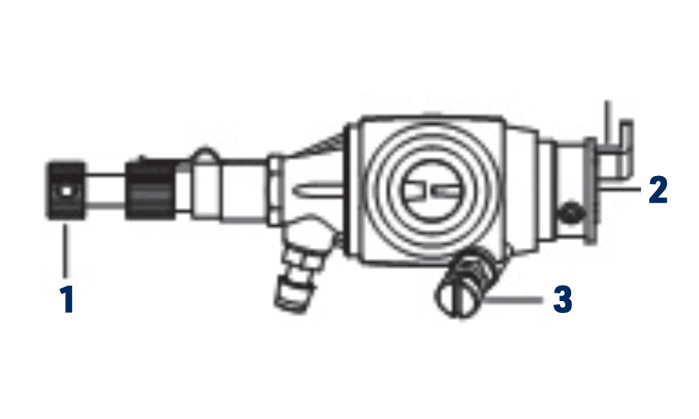
- Main needle: sets the basic air/fuel mixture at full throttle; lower-speed mixture then follows the carburettor’s metering system.
- Idle mixture needle: controls fuel delivery at low speed and during throttle transitions. Start with the factory setting and change it only if necessary.
- Idle stop screw: limits the throttle barrel’s travel.
Throttle servo
With the transmitter throttle trim fully lowered, set the linkage and servo travel so that full stick fully opens the barrel and low stick completely closes it. Raise the trim to obtain a reliable idle. Lowering it again must stop the engine.
Restoring the initial idle mixture setting
With the engine stopped, glow power disconnected and the fuel supply disconnected, use a short, clean, fuel-free tube on the carburettor fuel inlet to check gentle airflow. The legacy procedure uses mouth-blown air; use a clean hand-operated air bulb instead to avoid contact with poisonous fuel. Do not use compressed air.
- Initially close the throttle barrel to an opening no wider than a modeller’s pin, approximately 0.7 mm.
- Fit the clean test tube and open the main needle 1½ turns from gently closed.
- Following the original procedure, close the barrel completely for the airflow check. Apply gentle air and adjust the idle mixture needle until air just begins to pass.
- Open the idle mixture needle a further 1/2 turn.
- Continue the airflow check while opening the barrel. Airflow should change rapidly at about 15° from idle.
- Do not make the mixture excessively rich merely to lower idle speed. Close the throttle barrel slightly farther instead, then repeat the idle mixture adjustment.
Starting
Rotation is counterclockwise when viewed from the front. Secure the model or stand, keep everyone clear of the propeller and start with the recommended rich setting.
- With glow power disconnected, gently close the main needle without forcing its seat, then open it 1½ turns. Set the throttle about 1/3 open.
- For manual starting, cover the carburettor intake and turn the propeller counterclockwise several times to draw in fuel. Uncover the intake after priming. Alternatively, the original manual permits a few drops above the piston through the exhaust or plug opening, or briefly inverting the installed model. Use only enough fuel to prime; avoid flooding and refit removed parts before starting.
- For electric starting, leave the carburettor intake open. Choking while using an electric starter can draw in excessive fuel and cause hydraulic locking.
- Turn the propeller by hand with glow power disconnected to check free movement. A single revolution does not guarantee that all excess fuel has drained. If movement is obstructed, follow Clearing a flooded engine before applying power.
- Connect the glow supply. Apply the electric starter, or use a starting stick or heavily padded leather glove to flick the propeller sharply. Never use a bare hand.
- When the engine starts, slowly open the throttle fully and gradually close the main needle until the sound changes and speed rises. Disconnect glow power. If it stops because the mixture is too rich, close the needle about 30° and restart.
- Once running-in permits normal adjustment, close the main needle in 10–15° steps, pausing for the speed to respond, until further closure no longer increases speed. Then return to the richer operating setting, 20–30° open from peak, as shown in the idle sequence. Do not run a new engine at a lean peak-speed setting.
- If it never fires, check the glow plug and supply. If it starts for a few seconds and stops, open the main needle 1/2 turn, disconnect glow power, prime as required and retry. Look for fuel advancing through the supply tube as the initial priming charge is consumed.
Clearing a flooded engine
Disconnect glow power, close the main needle and remove the glow plug. Turn the engine with its plug opening down and gently move the propeller by hand to drain excess fuel away from people and ignition sources. For ABC engines, observe the restriction on passing top dead centre with the plug removed. Do not force the crankshaft or use the electric starter. Refit the plug and restore the needle setting once free rotation is confirmed; do not prime again immediately.
Break-in
Running-in allows the moving parts to bed together under operating temperature and load. Do not rush it.
- Fit the appropriate propeller, open the main needle 1½ turns from gently closed and start. Run for 2–3 minutes at the lowest speed that sustains running with a rich mixture.
- Close the main needle enough to increase speed and run for 10 seconds. Reopen it to the original rich position for another 10 seconds. Repeat until the tank is empty.
- Set a reliable idle using the sequence below.
- Restart, open the main needle a further 1/2–1 turn for rich running and run through 3–4 tanks.
- On subsequent flights or runs, gradually close the main needle towards the normal setting. After about 6–10 flights, the engine should run reliably at its normal setting. Retain the slightly rich margin described below.
Idle adjustment sequence
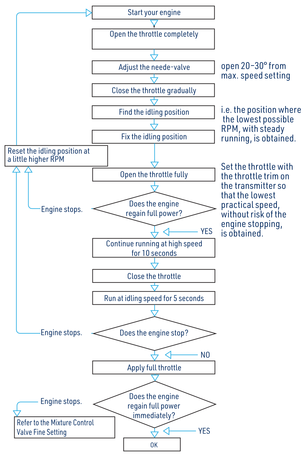
- Start and warm the engine, open the throttle fully and disconnect external glow power. Set the main needle 20–30° farther open than the maximum-speed position.
- Close the throttle gradually to find the lowest steady speed. Set the transmitter trim for the lowest practical idle without stopping.
- Open the throttle fully. If the engine stops, raise the idle setting slightly and repeat.
- Once full power returns, run at high speed for 10 seconds, close the throttle and idle for 5 seconds.
- Apply full throttle again. If it stops or does not regain full power promptly, follow Fine idle mixture adjustment, then repeat the sequence until transitions are reliable.
Fine idle mixture adjustment
Start the engine, gradually close the throttle and set idle. Hold the model securely and slowly raise its nose from level. Adjust from behind the propeller; stop the engine and disconnect glow power before touching a control that cannot be reached safely.
- If speed rises, close the idle mixture needle slightly and repeat until speed remains unchanged when the nose is raised.
- If the engine runs irregularly or stops, open the idle mixture needle slightly and repeat.
The main and idle mixture settings affect each other. A substantial change to either may require fine adjustment of the other.
Troubleshooting
Stop the engine and disconnect glow power before inspecting, removing or replacing parts. Reconnect it only for a controlled starting test.
| Symptom | Cause | Remedy |
|---|---|---|
| Engine does not fire | Insufficient starting speed | Recharge the starter battery; use a firm, safe starting action. |
| Discharged glow battery | Recharge the battery. | |
| Burnt-out glow filament | Replace the plug and check that the glow supply does not exceed its rated voltage, normally 1.2–1.5 V. | |
| Faulty glow lead or clip | Check the wiring and test with a known good plug. | |
| Flooding | Follow the flooded-engine procedure above; do not prime again before the next attempt. | |
| Insufficient priming | Repeat the priming procedure with glow power disconnected. | |
| Engine fires but does not keep running | Incorrect glow heating | Check for glow voltage that is too low or too high. |
| Mild flooding | After about 10 unsuccessful flicks, disconnect glow power and wait a few minutes. Check free rotation before retrying. If it still will not run, drain excess fuel as described above. | |
| Insufficient starting speed | Use a firmer safe flick, or recharge the starter battery. | |
| Engine fires once or twice, then no longer fires | Discharged glow battery | Recharge the battery. |
| Insufficient priming | Repeat the priming procedure with glow power disconnected. | |
| Engine starts, loses speed and stops | Mixture too rich | Close the main needle 1/2 turn (180°), wait a few minutes and restart without priming. |
| Engine starts, gains speed and stops | Fuel is not reaching the engine | Check the tank contents, kinked or split fuel tubing, and dirt in the carburettor. |
| Engine stops when glow power is disconnected | Mixture too rich | Close the main needle slightly. |
| Unsuitable plug/fuel combination | Use a suitable fuel or glow plug. |
Maintenance
Fuel-system cleanliness
Do not run the engine in dusty conditions. Protect it from dust stirred up during ground running. Flush the tank with methanol or fresh glow fuel before installation. Fit an in-line filter between tank and engine and a pickup filter in the fuel supply bottle or at the pump inlet. Keep the supply bottle closed when not in use. Inspect and clean the filters and carburettor nozzle regularly.
After flying
- Drain the tank at the end of the session.
- With the model secured in the normal outdoor running position, reconnect glow power and restart as necessary to consume fuel remaining in the engine. When it no longer fires, disconnect glow power and turn it with the starter for 4–5 seconds while still warm.
- With glow power still disconnected, introduce a small amount of fresh glow fuel containing lubricant but no nitromethane. Turn gently by hand to check free rotation, then use the starter for 4–5 seconds to distribute lubricant. Drain residue. This flush is particularly useful after nitromethane fuel to limit corrosion from combustion residue.
- Before extended storage, apply a few drops of suitable after-run oil to protect internal parts from corrosion.
Four-stroke valve inspection
Valve clearances are set at the factory. Check them periodically; if you fly every weekend, inspect about every 3–4 months. Also check after prolonged operation with reduced power, dismantling or repair following a crash. See Four-stroke valve clearance in the appendix.
Appendix
Dimensions (mm)
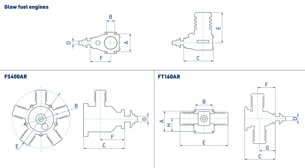
| A | B | C | D | E | F | G | H | |
|---|---|---|---|---|---|---|---|---|
| AP06A | 24 | 10 | 45 | M4 | 38.5 | 33 | ||
| AP09A | 30 | 11 | 58 | M5 | 43.5 | 41 | ||
| S15AII | 31.5 | 11 | 62 | M5 | 49.8 | 42.8 | ||
| S32AII | 38 | 15 | 74.9 | 1/4″–28 | 56.7 | 53.2 | ||
| S36AII | 38 | 15 | 74.9 | 1/4″–28 | 56.7 | 53.2 | ||
| S40AII | 44 | 17.5 | 84.3 | 1/4″–28 | 70.2 | 60.3 | ||
| S46AII | 44 | 17.5 | 85 | 1/4″–28 | 70 | 60 | ||
| S52AII | 44 | 17.5 | 85.8 | 1/4″–28 | 70.9 | 60.7 | ||
| S61AII | 52 | 25 | 97.8 | 5/16″–24 | 80.3 | 68.5 | ||
| S91A | 52 | 25 | 97.5 | 5/16″–24 | 84.7 | 67 | ||
| 108A | 58 | 25 | 105.3 | 3/8″–24 | 90 | 73.7 | ||
| 180AR | 68 | 36.5 | 133.7 | 3/8″–24 | 108 | 96.6 | ||
| FS-30AR | 36 | 14 | 64.7 | 1/4″–28 | 71 | 46.8 | ||
| FS-52AR | 44 | 17.5 | 80.6 | 1/4″–28 | 82.4 | 59.2 | ||
| FS-70AR | 50 | 21 | 89 | 5/16″–24 | 97.4 | 65.3 | ||
| FS-80AR | 50 | 21 | 90 | 5/16″–24 | 98.3 | 65.3 | ||
| FS-91AR | 52 | 25 | 90 | 5/16″–24 | 100 | 65.3 | ||
| FS-120AR | 58 | 25 | 106 | 5/16″–24 | 116.3 | 78.3 | ||
| FS-180AR | 58 | 25 | 111.8 | 3/8″–24 | 120 | 80.8 | ||
| FT-160AR | 80 | 68 | 120 | 3/8″–24 | 195.3 | 69.5 | 56.5 | 56.5 |
| FS-400AR | Ø122 | 160.5 | 3/8″–24 | Ø227 | 78 |
Four-stroke valve clearance
Use 0.04mm and 0.10mm feeler gauges, a 2mm hex key, a No. 5 open-ended spanner and a small flat screwdriver. The original manual lists O.S. MAX set No. 72200060 as an alternative tool set; confirm its suitability and availability with a model specialist.
Check and adjust valve clearances only with the engine cold and glow power disconnected.
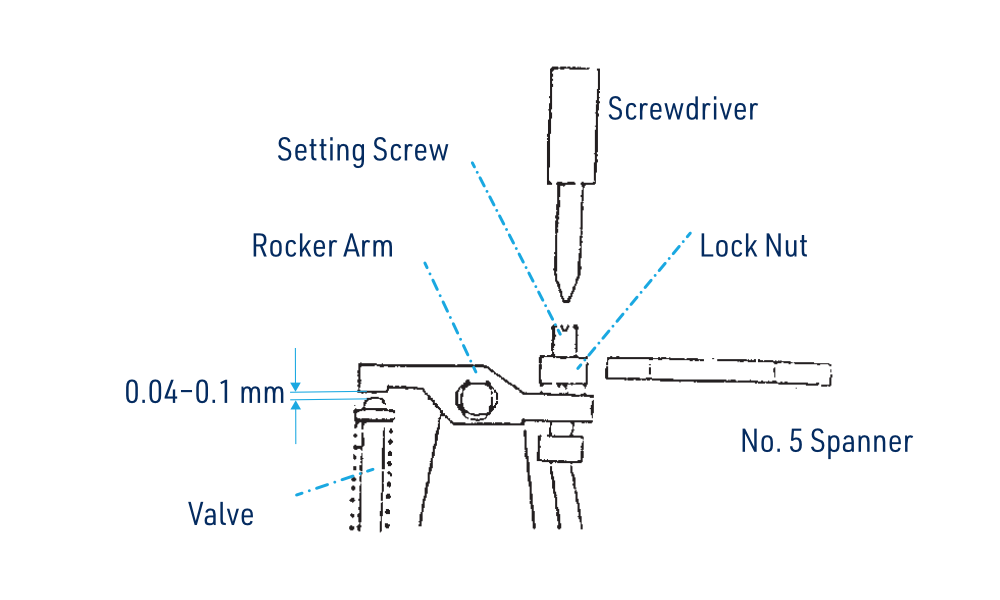
- Loosen the two socket-head screws and remove the rocker cover.
- Turn the propeller 2 revolutions counterclockwise, observing the valves. Continue until compression is felt, then turn a further 1/4 revolution to bring the piston to top dead centre on compression, with both valves closed.
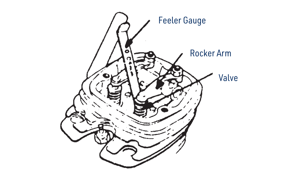
- Measure between the rocker arm and valve stem. The required clearance is 0.04–0.10 mm: the 0.04mm feeler should pass, while the 0.10mm feeler should not.
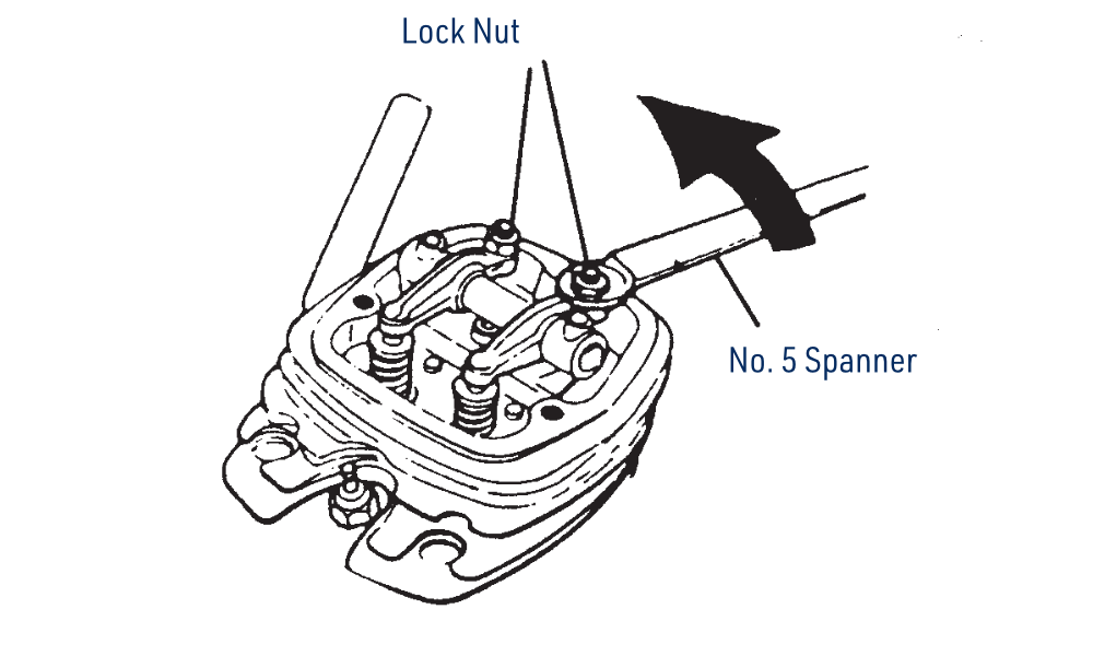
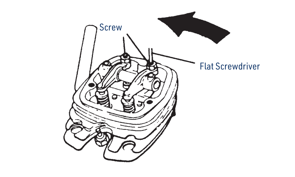
- If adjustment is necessary, loosen the rocker-arm locknut carefully with the No. 5 spanner and turn the adjusting screw about 1/2 turn counterclockwise to increase the gap.
- Insert the 0.04mm feeler and turn the screw gently clockwise until it just touches the gauge.
- Hold the screw still and retighten the locknut. Remove the gauge, turn the engine through its cycle and recheck both valves. Refit the rocker cover.
Too little clearance can prevent a valve from closing properly and make starting difficult. Excessive clearance reduces valve opening and can reduce power.
Preparing the engine for service
- Clean the engine and drain all fuel. Include proof of purchase, a concise but detailed fault description, your return address, daytime telephone number and e-mail address.
- Send only the items requested by the service technician. Do not include fuel, batteries, chargers, glow equipment, manuals or unrelated accessories.
- Pack the engine securely in a strong, correctly sized cardboard box so that it cannot move. Keep loose paper or foam particles out of the engine; place the engine or loose packing in a sealed bag if necessary.
- Agree shipping arrangements with the service centre and use suitable tracking and insurance. Keep a record of the shipment.