KAVAN Mirai V-tail 1995mm - Instruction manual
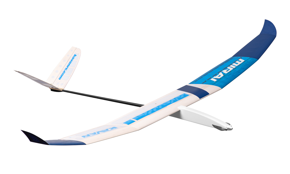
KAVAN Mirai V-tail - kit
Introduction
The KAVAN Mirai V-tail is a 1995mm thermal glider kit with a V-tail, a light balsa and plywood structure and a carbon tail boom. Parts are supplied for both the unpowered glider and electric glider versions. It is intended for recreational and competition flying with rudder, elevator and airbrake control; the electric version also has throttle control.
The interlocking CNC-cut parts help with alignment, but this kit is intended for modellers with some building experience. Construction uses the balsa, plywood and spruce techniques needed for larger models. The removable tail and sectional wing simplify transport.
Before you start
- If you are not an experienced RC pilot, plan to have a fully competent pilot check your completed model and help you with your first flights. Even though we have tried to provide you with a thorough instruction manual, RC models are rather complicated, and an experienced modeller can quickly check over your model to ensure your first flights are successful.
- Please assemble your model according to these instructions. Do not modify or change your model in any way. Doing so may adversely change its flying characteristics.
- Before you begin, check the entire contents of this kit to make sure no parts are missing or damaged. It will also help you to become familiar with each component of your plane. If you find that any of the parts are either missing or damaged, contact your dealer immediately for replacement.
- Trial fit each part before gluing it in place. Before assembling, make sure you are using the correct part and that it fits well. No amount of glue can make up for a poorly fitting part.
- The manual contains a drawing showing the default Centre of Gravity (CG) position and recommended control surface throws. Please note it is essential to keep the recommended CG position for the first flight, or the model could be unstable, hard to control or even unable to fly. Later, you can fine-tune the CG position to suit your flying style and skills.
Your dealer cannot accept kits for return if construction has begun.
Precautions
This RC model is not a toy. Use it with care and strictly following the instructions in this manual.
Assemble this model following strictly these instructions. DO NOT modify or alter the model. Failure to do so, the warranty will lapse automatically. Follow the instructions to obtain a safe and solid model at the end of the assembly.
Children under the age of 14 must operate the model under the supervision of an adult.
Make sure the model is in perfect condition before every flight, check that all the equipment works correctly and that the model is undamaged in its structure.
Fly only on days with a light breeze and in a safe place away from any obstacles.
This RC model you will build and fly is not a toy! Although it may seem light and slow in flight it is capable of serious bodily harm and property damage. It is your responsibility and yours alone to build this model correctly, properly install RC equipment and motor, test the model and fly following all safety standards (and common sense) as set down in Safety Codes valid in your country. If you are just starting RC modelling, consult your local hobby shop or an experienced modeller in your local RC club to find a good instructor.
You must build the model according to the instructions. Do not alter or modify the model, as doing so may result in an unsafe or unflyable model. Take time to build straight, true and strong. Use proper radio and other equipment that is in first-class condition, properly install all the components and test their correct operation before the first and any further flight. Fly the model only with competent help from a well-experienced modeller if you are not already an experienced RC pilot.
We, as the kit manufacturer, can provide you with a top-quality kit and instructions, but ultimately the quality and flyability of your finished model depends on how you build it. Therefore we cannot in any way guarantee the performance of your completed model, and no representations are expressed or implied as to the performance or safety of your completed model.
Features
- High-performance thermal glider or electric glider
- Designed and manufactured in the Czech Republic
- Extensively pre-processed
- Easy to build
- Great flight characteristics
Technical specifications
| Wingspan | 1995 mm |
|---|---|
| Length | 1210 mm |
| All-up weight | From 420 g |
| Wing section | Special RES HB |
| CG position | 80 mm nominal; 78–82 mm adjustment range; 78 mm for the first flight |
| Controls | Rudder, elevator, airbrake, (throttle) |
Set contents
CNC-cut balsa and plywood parts, spruce spars and balsa sheeting, carbon tail boom, set of accessories, sticker decals sheet, construction plan in 1:1 scale, and a user manual.
Recommended RC equipment
- Rudder and elevator servo: 2× KAVAN GO-09 Plus, 2× Hitec HS-53
- Airbrake servo: KAVAN GO-13MG, Hitec HS-65MG, Dymond D47
- Receiver battery: Panasonic Eneloop AAA 800mAh 4.8 V pack
- Brushless motor: KAVAN PRO 2225-1600
A V-tail mixer is required to combine rudder and elevator commands on the two ruddervators. The glider needs at least 3 channels with the airbrake, or 2 without it. The electric version needs an additional throttle channel. The catalogue recommends 9–15g micro servos with 1.5–2 kg·cm torque. The electric installation uses a Ø22mm, 150–200W brushless motor, a compatible 20A ESC and a 2S or 3S LiPo 450mAh battery. Match the motor, propeller, ESC and battery as a complete system; do not assume every battery and propeller combination is suitable.
Recommended glues
Unless stated otherwise, use medium cyanoacrylate (CA) glue (KAV56.9952). D-box sheeting and wing ribs are better glued using a water-resistant white aliphatic resin, like our White Glue SUPER KAV56.9960/KAV56.9961 (alternatively, you can use this sort of glue for most of the wood-to-wood joints). The highly loaded parts (wing roots, wing main spars, firewall etc.) should be glued together using 30-minute (or slower) epoxy (KAV56.9965 / KAV56.9966 / KAV56.9967) offering high strength and enough time for the correct positioning.
Recommended covering material
Iron-on films such as KAVAN Covering film, ORACOVER® or ORALIGHT® are suitable for the Mirai. Use a light covering to preserve the model’s performance.
Tools and accessories
- Very sharp precision knife (KAV66.770 with no. 11 blades)
- Scissors
- Electric drill with drill bits
- Wire cutter
- Long nose pliers
- Screwdrivers
- Razor saw
- Sandpaper No. 80, 100, 180, 360–400
- Needle files
- Soldering iron and solder
- Clothing pegs
- Modeller's pins (KAV66.0355)
- Epoxy mixing stick and vessel
- Masking tape, clear sticky tape
- Rubbing alcohol (for cleaning up excessive epoxy)
- Paper tissue or soft cloth (for cleaning up excessive epoxy)
- Straightedge with scale
- Square edge
- Thin clear plastic film (for protecting the building plan)
- Permanent marker
- Modeller’s sealing iron (KAV66.8335), heat gun (for covering)
- Lightweight balsa filler (KAV56.9980 / KAV56.9981 / KAV56.9982)
Main section
Model assembly
Tail surfaces
Everything has been designed extremely light; yet strong enough. The tail feathers are removable for easy transport/storage.
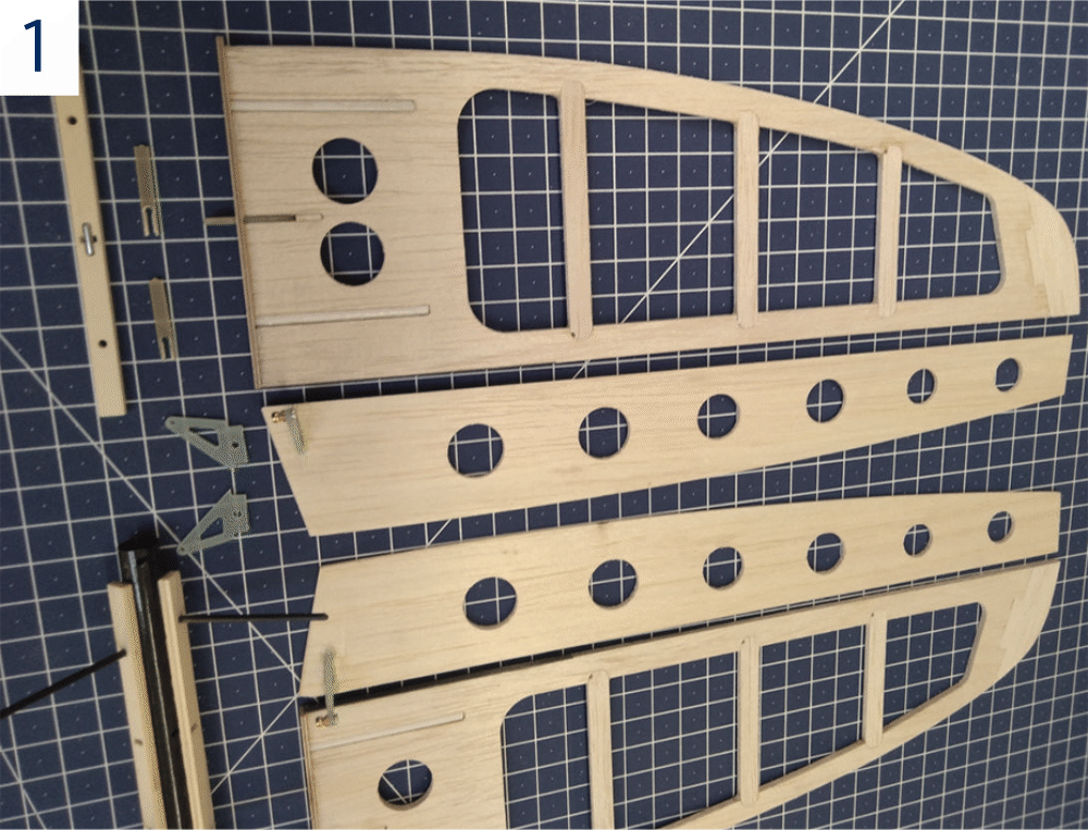
- Trial fit the parts of the stabilisers and control surfaces – no glue yet! Sand as necessary to obtain a perfect fit. (Fig. 1)
- Tack glue the plastic tubes V14 into the stabilizers with a few drops of CA.
- Roughen the surface of the 3×0.5mm V10 carbon spars using no. 150 sandpaper and glue them with medium CA to the trailing edges of the stabilizers.
- Glue together all the balsa parts using medium CA or aliphatic resin.
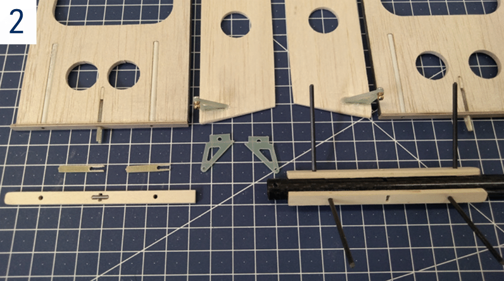
- Glue the stabilizer root ribs V4L/V4R (1.2 mm plywood). Use the V16 carbon rods inserted into the V14 tubes as alignment pins for the root ribs. Double-check the root ribs were straight and square to the stabilizers. Take care the V16 rods were not glued into the stabilizers in this step. (Fig. 2)
- Put the tail surfaces aside for now. They will be finished after the tailplane seats are installed to the tail boom.
Fuselage (glider version)
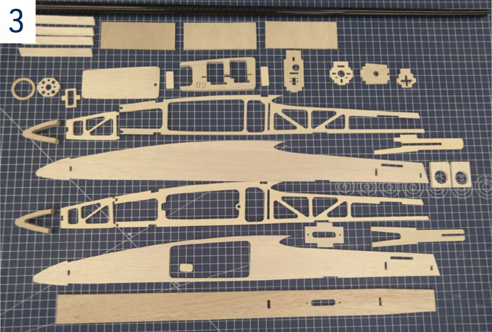
- Trial fit the parts of the fuselage – no glue yet! Sand as necessary to obtain perfect fit. (Fig. 3)
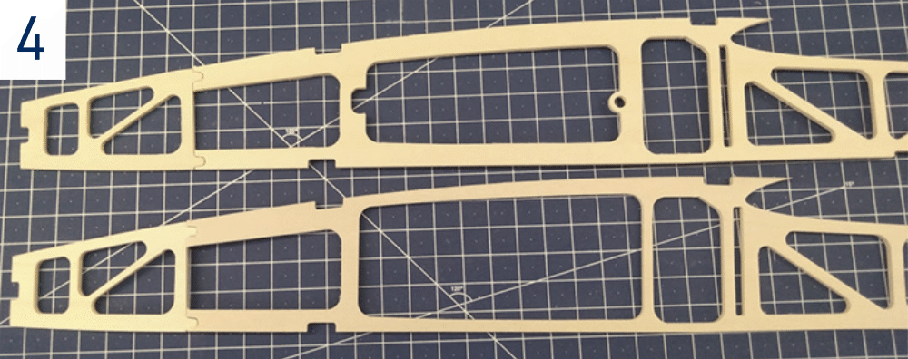
- Glue the Lite Ply reinforcement plates F3 and F5L to the inner side of the F17L fuselage side (with the large opening for the F16 hatch). Glue the plates F3 and F5R to the inner side of the F17R fuselage side (without the hatch opening). (Fig. 4)
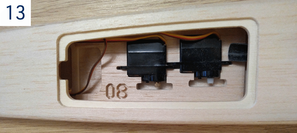
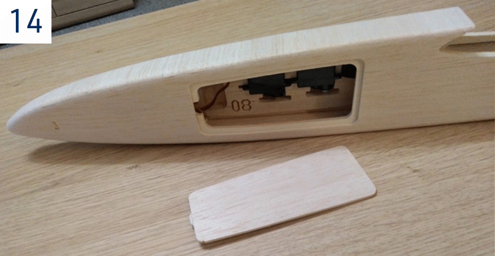
- Glue the F6 locking plate to the front of the F16 hatch. The locking plate has to match the position of a notch in the F5L reinforcement plate and the hatch matched the opening in the F17L fuselage side. The pair of F21 magnets will be epoxied into the F16 hatch and F5L plate only after the fuselage is covered – otherwise the high temperature of your sealing iron might demagnetize the magnets. (Fig. 14)
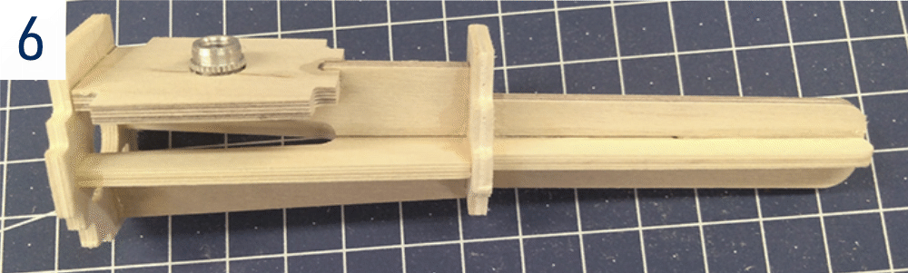
- Epoxy together the tail boom holder consisting of the Lite Ply part F13 and plywood parts F10 and F14. Attach the F9 wing bolt plate with the M5 aluminium captive nut epoxied in place. Insert the entire assembly of the tail boom holder between the fuselage sides. Now you can start gluing the fuselage from the rear to the nose. (Fig. 6)
- Glue together the nose part of the fuselage; do not forget bevelling the edges of the fuselage formers and F18 and F19 Lite Ply braces as required. (Fig. 9)
- Epoxy the F9 wing bolt plate and the tail boom holder assembly in place.
- Bevel the F1 nose blocks and glue in place.
- Partially cut (ca 1 mm deep) and crack the fuselage sides along the front edge of the F2 fuselage former and glue them to the F1 blocks (the cut line is to be soaked with thin CA before the final sanding).
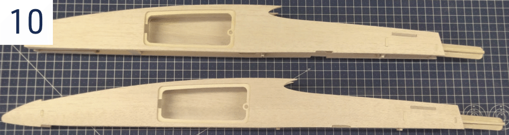
- Epoxy the tow hook plate F15 in place. Glue the F20 carbon ballast tube into the holes in F7 and F8 formers. (Fig. 10)
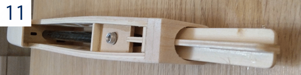
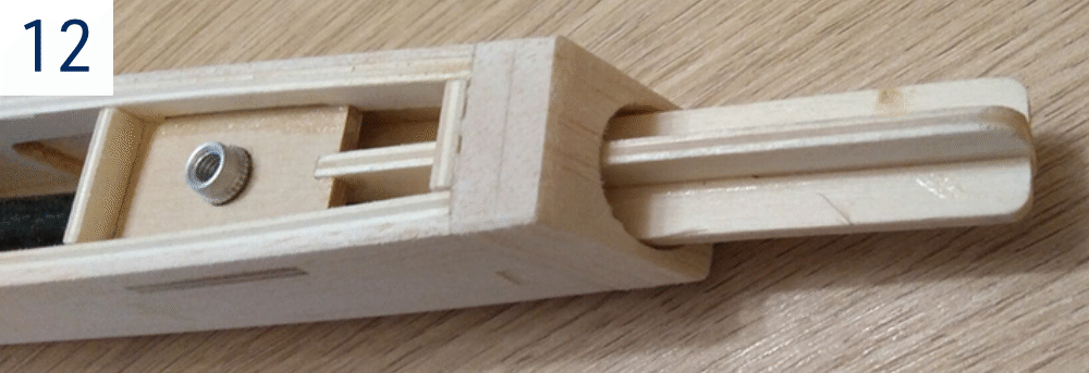
- Glue the upper and lower 2.5 mm balsa sheeting to the fuselage. Slide the tail boom tube F22 onto the tail boom holder – do not glue yet. Fit and glue the balsa fairing plates F11 and F12 in place. Carefully match all the parts so the tail boom had a tight fit but remained still easily detachable. (Fig. 11)+(Fig. 12)
- Sand the entire front part of the fuselage. Ensure the parts including the F11/F12 fairing created a smooth transition between the fuselage and the tail boom. (Fig. 14)
- Insert the V16 carbon rods into the pre-drilled holes in the tail boom; glue them in place. The bottom ends of the rods should stick out by ca 0.5 mm from the tail boom (there is an opening in the bottom side of the tail boom to accommodate the tail skid V12) – refer to Det. D on the building plan. (Fig. 2)
Fuselage (electric version)
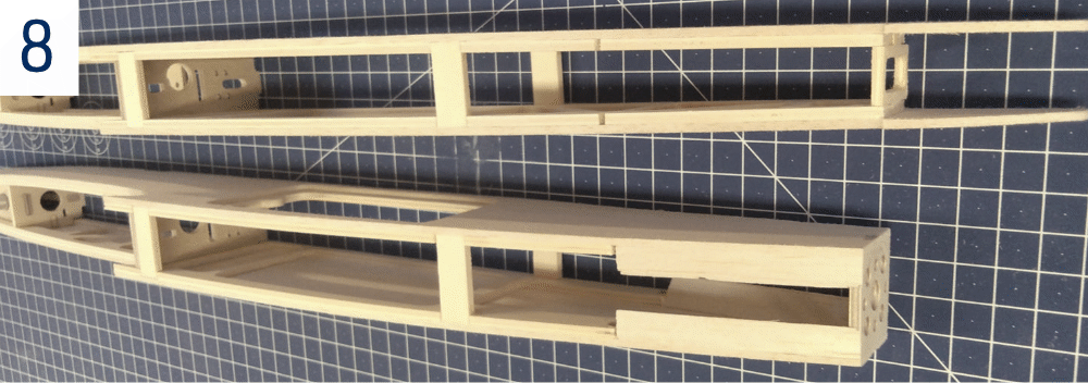
- The building sequence of the electric version fuselage is basically the same as with the glider version except for the firewall, nose and servo tray. Also, the F20 ballast tube is not to be used.
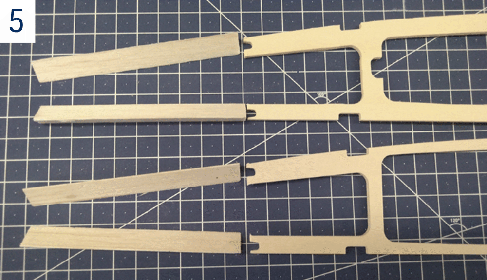
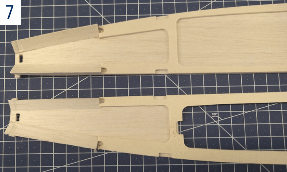
- Instead of Lite Ply F3 reinforcement plates, glue the balsa triangular sticks E4 along the edges of fuselage sides F17L and F17R. (Fig. 5)+(Fig. 7)
- Epoxy the E3 servo tray behind the F7 fuselage former.
- Epoxy the firewall E2 in place. Before you epoxy the firewall in, make sure the openings and holes in the firewall match your motor – make any changes as necessary or cut a new firewall to match your motor perfectly.
- Once the bottom and upper sheeting is in place cut the fuselage sides flush with the front edge of the E2 firewall. Temporarily install your motor and use the spinner as a jig to align the E1 plywood ring. Once satisfied, epoxy it in place. Sand the nose to the desired shape matching your spinner. (Fig. 9)+(Fig. 10)
Tail surfaces - continued
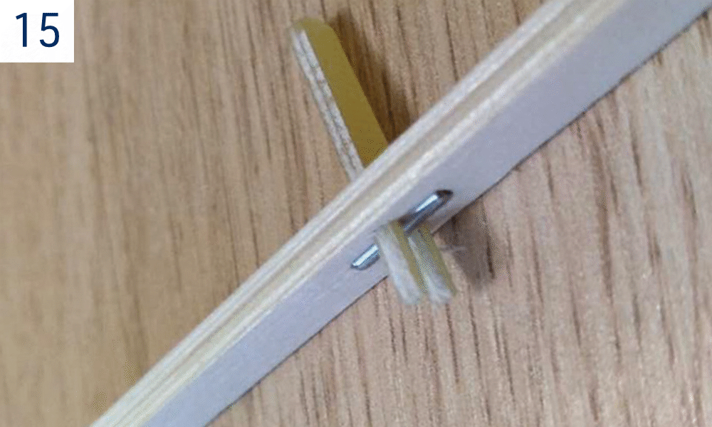
- Glue the V9 pins into the tailplane seats V8L and V8R. (Fig. 15)
- Slide tailplane seats V8L and V8R onto the V16 carbon rods.
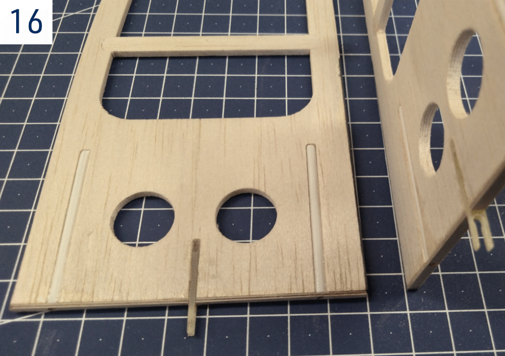
- Insert the V13 tailplane locks into the notches in the stabilizers (do not glue yet). (Fig. 16)
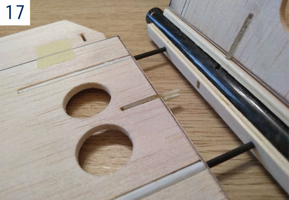
- Slide the stabilizers onto the V16 carbon rods and push against the V8R/V8L seats until you hear the click announcing the V13 lock has engaged the V9 pin of the stabilizer seat. Tack glue the locks into the stabilizers with a few drops of CA. (Fig. 17)
- Push the stabilizers together with the tailplane seats to the tail boom and tack glue the seats to the tail boom (apply the cyano sparsely; keep away from the locks and V16 carbon rods).
- Remove the stabilizers and epoxy the V8R/V8L seats to the tail boom. Work thoroughly, but apply the epoxy sparsely. Prevent the glue from running into the openings for the stabilizer locks.
- The ruddervator horns V11 as well as the V12 tail skid will be glued in later after the tail surfaces are covered.
Wing
Wing centre section
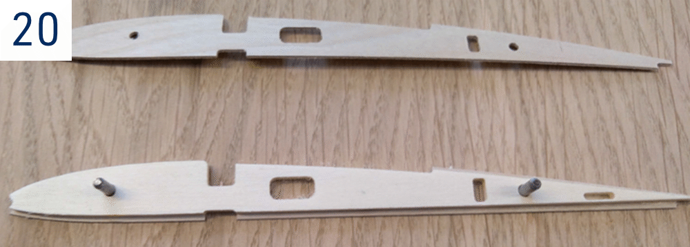
- Epoxy together the wing central ribs W3 and W4. Insert 3 mm beech dowels into the holes in order to obtain the correct match.
Note
Make a left and right pair of ribs. (Fig. 20)
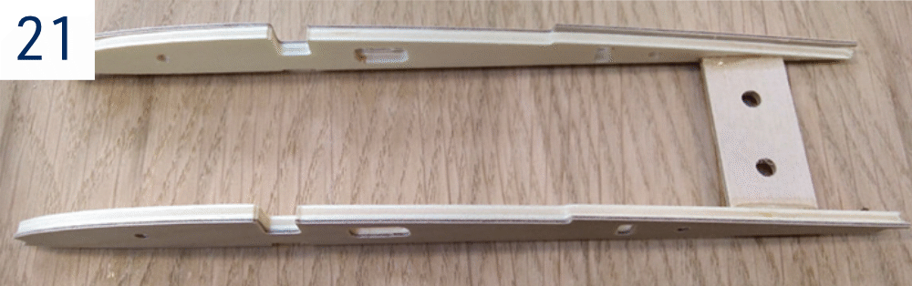
- Epoxy the W10 wing fixing bolt plate between the central ribs. (Fig. 21)
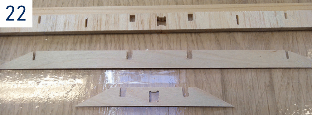
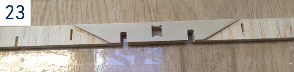
- Epoxy together the parts of the W13 main spar shear webbing; the short 0.8 mm ply W11 joiner (with a hole in the centre) to the front side, the W12 long joiner to the rear side. (Fig. 22)+(Fig. 23)
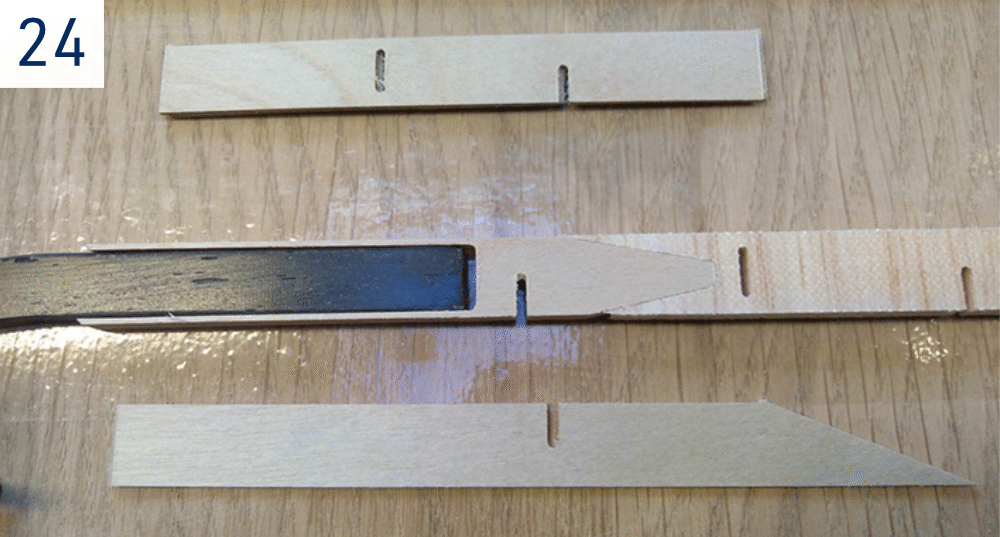
- Make bays for P32 wing carbon joiners; epoxy together the W14 front (shorter) 0.8 mm ply plate, 5 mm ply central plate W15 and rear 0.8 mm ply (longer, slanted edge) W16 plate. Prevent the epoxy hardening inside the bays – put the parts together with the P32 carbon joiner inserted, then immediately remove the joiner (do not forget to clean the joiner using paper tissue and rubbing alcohol before the glue sets). (Fig. 24)
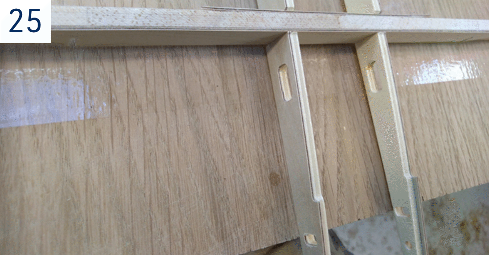
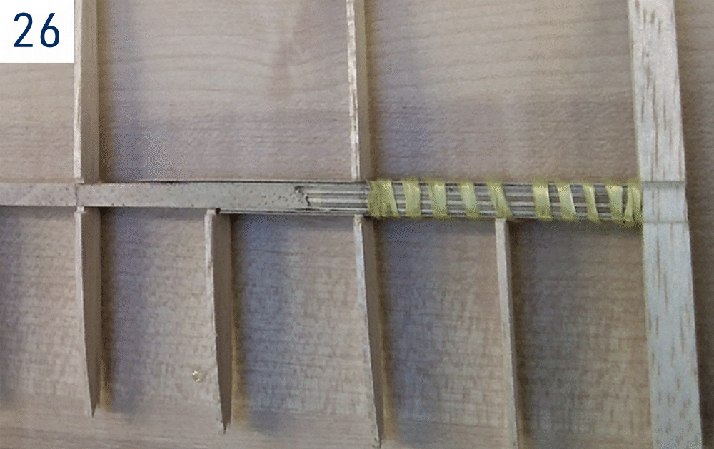
- Slide all ribs onto the mains spar shear webbing (no glue yet!). Bind the joiner bays with the provided Kevlar thread and soak with medium CA. (Fig. 25)+(Fig. 26)
- Engage the ribs in the notches of W17 to establish their spacing. Initially glue the 5×5mm W30 leading edge only to the W5 end ribs.
- Insert the W27 rear spar and trial fit the W30 leading and W17 trailing edges. Sand to fit as necessary. Build the wing centre section over the plan protected with thin clear plastic film. Glue the structure with medium CA, or use aliphatic resin for the ribs at the W13 main spar webbing. Keep the leading edge bonded only to the end ribs until fitting the upper sheeting in the next step.
- Edge glue together the W24 upper D-box sheeting (1.5 mm balsa) and the W26 upper 8×2 mm spruce stick main spar. Once cured, glue it to the wing using aliphatic resin. Use a hardwood stick positioned along the leading edge to push the balsa sheeting straight and even to the W30 leading edge.
- Glue the W26 lower 8×2 mm spruce stick main spar in place.
- Bevel both W5 end ribs of the wing centre section using the supplied 7° dihedral jig. Then glue the W6 3 mm Lite Ply end ribs. You might find easier doing it later; with the P32 joiners inserted and finished wing outer panels attached.
- Glue the W21 airbrake frame to the upper side of the wing. Insert and glue the airbrake bay reinforcement plate W20 (balsa 1.5 mm) into W5, W7 and W8 ribs. Cyano the W34 fibreglass bushings for the airbrake torsion bar onto W3/W4 and W7 ribs. Insert the 3 mm carbon torsion bar W37 into the bushings. Do not forget to slide the W36 control horn in the centre. Do not glue yet! The control horn and airbrake levers are to be glued in place once the wing is covered and the servo and airbrakes fitted (refer to Det. C).
- Glue the W29 magnet holders to the bottom side of W21 airbrake frames. The pairs of W33 magnets will be epoxied into the holders W29 and airbrakes W22 and W23 only after the wing is covered.
- Glue the 1.5 mm balsa W28 upper centre sheeting (supplied in 2 pieces) and the bottom W19 sheeting in place over the W3 ribs.
- Do not glue the W25 airbrake servo hatch. It will remain removable for easy access to the servo. You can secure it using e.g. small wood screw (not supplied in the kit) to the 5 mm plywood holders W32. Do not forget to cut the opening for the wing fixing bolt into the balsa sheeting.
- Epoxy the W1 central riblet with the wing alignment pin sandwiched between two W2 riblets in place. Glue the 1.5 mm front bottom sheeting W18 between the W3/W4 ribs.
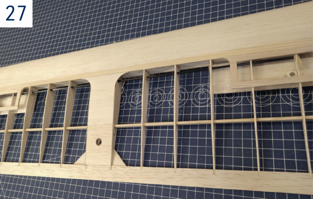
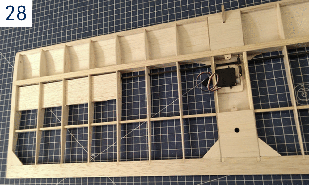
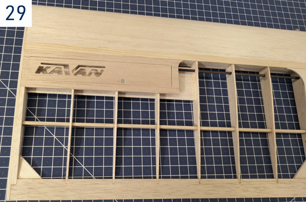
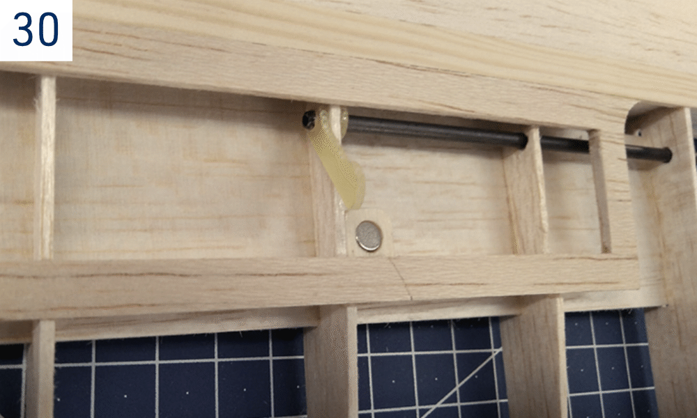
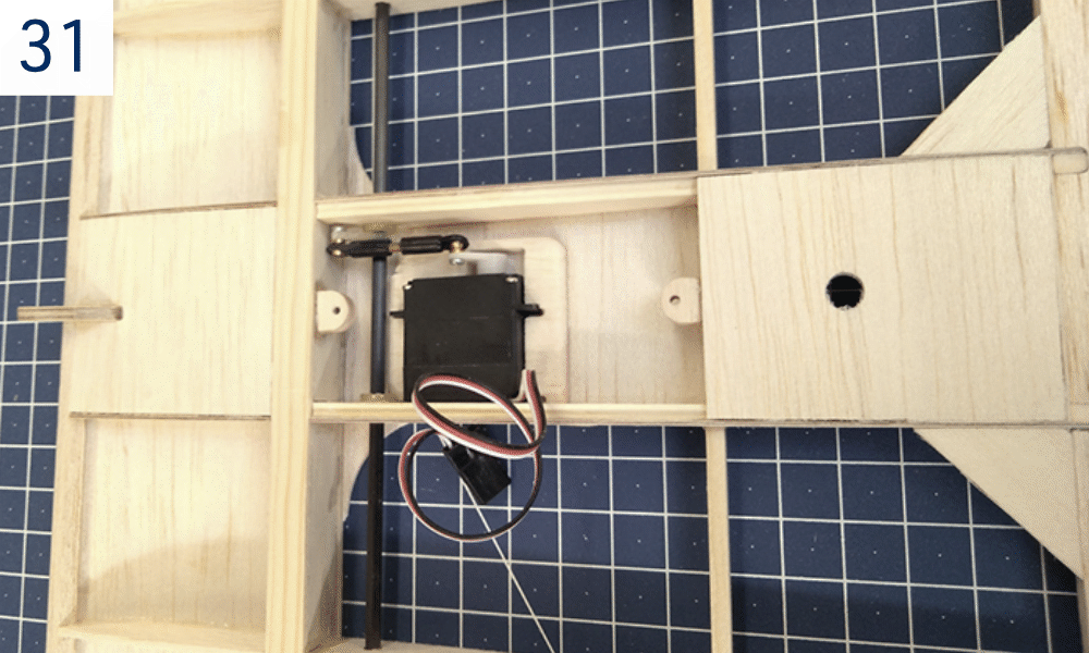
- Sand to fit and glue the 2.5 mm balsa gussets W38 in place. (Fig. 27)+(Fig. 28)+(Fig. 29)+(Fig. 30)+(Fig. 31)
- Fine sand the entire wing centre section (incl. the airbrake).
Wing outer panels
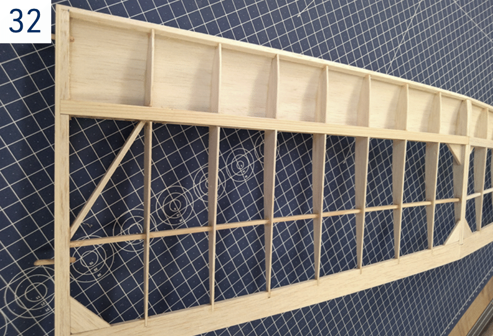
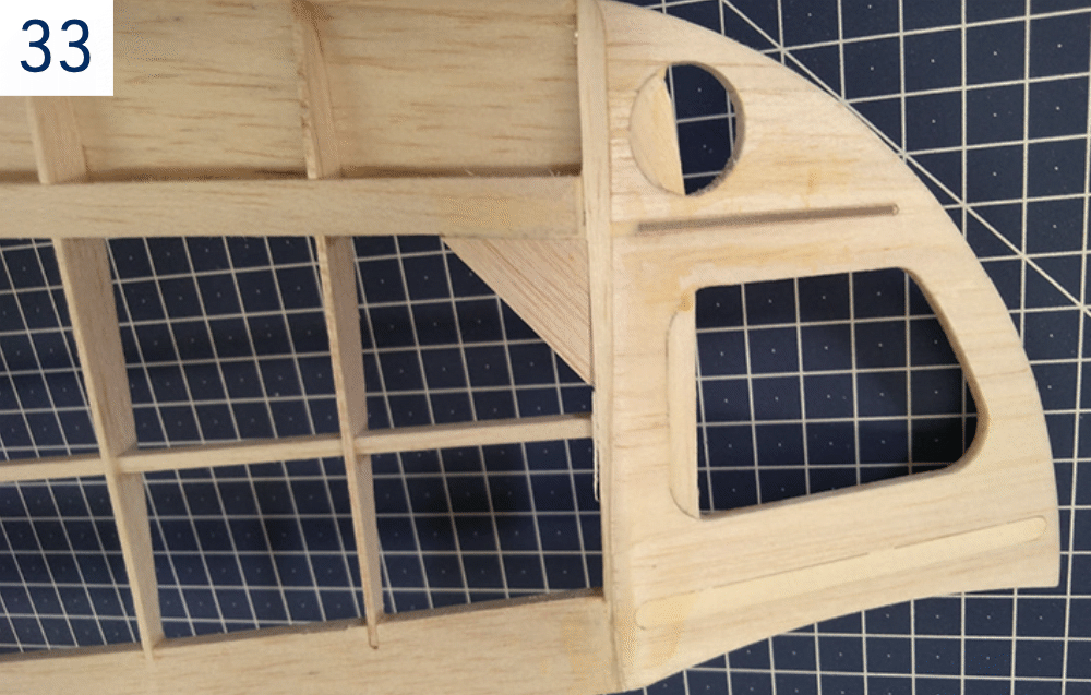
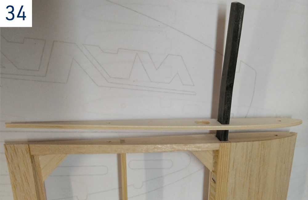
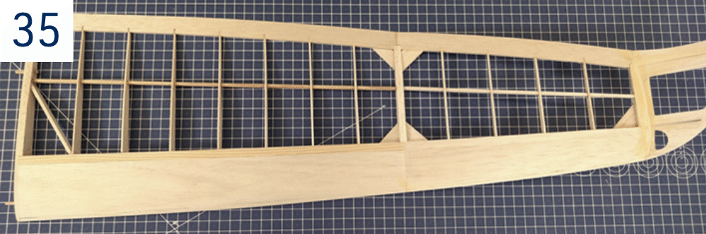
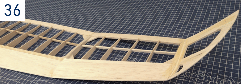
(Fig. 32)+(Fig. 33)+(Fig. 34)+(Fig. 35)+(Fig. 36)
- The wing outer panels are to be constructed in the same manner as the wing centre section. The main difference is that the inner part and the outer winglet are built as one part on a flat surface. Once the structure is finished, you will cut it between the end/root ribs; then bevel to obtain the correct dihedral and glue together.
- Glue together both two wing outer panels over the building plan protected with a sheet of thin clear plastic film (remember – you are building left and right wing panels!). Please note the inner spars are made of spruce sticks P33 resp. P23, whilst the winglet spars are made of balsa sticks (P34 and P31).
- Glue the top D-box sheeting P27 and P28 in the same manner as the wing centre sheeting W24.
- Sand the wing tip flat, glue the P17 winglet fairing in place and bevel it to the required 35° angle. Insert the P29 plywood joiner and sand the P18 wing tip to fit. Once satisfied glue the joiner and wing tip in place.
- Sand to fit and glue the 2.5 mm balsa gussets P33 and the P34 diagonal braces made of 5×3 mm spruce stick in place.
- Cut off the outer winglets between the end ribs P10 and P11; bevel the P11 ribs using the supplied 7° dihedral jig. Epoxy the wing panels and winglets together.
- Bevel the P2 root ribs of the wing outer panels using the supplied 7° dihedral jig. Trial fit the P32 carbon wing joiner into the respective bays; there should be a tight fit, no play. If there is a significant play, put some epoxy into an appropriate area of the joiner and sand as necessary once the glue hardens.
- Glue the 3 mm Lite Ply P1 root ribs with 3 mm beech alignment pins P30 in place.
- Fine sand the entire wing's outer panels.
Covering
- Thoroughly sand the surface of all parts with no. 360–400 sandpaper and carefully vacuum all the dust (the iron-on film does not stick well to a dusty surface; the dust also contains hard grains released off the sandpaper capable of ruining the smooth coating of your sealing iron quickly).
- Use as light iron-on film as you can get (KAVAN Covering film, Oracover®, Oralight® etc. – not supplied in the kit). Follow the instruction manual supplied with the covering film of your choice please.
Hinging the control surfaces
- Use strips of high-quality hinging tape (available in hobby shops) or strips of the same iron-on film you used for the covering. Remember to apply the tape with the control surface deflected to the limit in order to get free movement of the particular control surface.
Pushrod installation
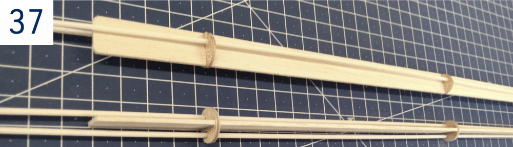
- Tack glue the pushrod tubes at a minimum of five points to the 1.5 mm balsa holder with the three plywood formers supplied in the kit. Do not shorten the tubes yet – they will have to go all the way into the front part of the fuselage. The push rod tubes go all the way through the tail boom tube. (Fig. 37)
- Insert the balsa holder with pushrod tubes into the tail boom; align with the front part of the fuselage. Once satisfied tack glue the holder to the tail boom tube.
Tail boom installation
- Attach the wing centre section to the fuselage and secure with the M5 nylon bolt. Attach and secure the tail surfaces to the tail boom with the push rod tubes installed in their holder (the holder prevents the tubes from getting loose and keeps any unwanted play in the elevator and rudder linkage next to zero). Slide the tail boom onto the holder on the fuselage front part. Thread the push rod tubes through the holes in F10, F8 and F7 formers.
- Check that the fuselage is straight-looking from above. Align the V-tail symmetrically to the trailing edge of the wing when looking from behind. Once satisfied use 30 min epoxy to secure the tail boom in place. Double-check the correct alignment of the wing, fuselage and tailplane before the glue hardens.
Servo installation
Rudder and elevator servos installation
- The ruddervator servos are to be installed into their servo tray F23 under the F16 hatch (glider) or into the E3 servo tray under the wing (electric version). Cyano the pushrod tubes into the fuselage formers.
- Solder the M2 brass threaded couplers to one end of the piano wire pushrods, attach the M2 ball links and fasten them to the ruddervator horns. (Fig. 1)+(Fig. 2)
- Fit the V-tail to the fuselage; insert the control horns into the ruddervators – do not glue yet. Set the servos in a neutral position with your radio on and mark the correct length of the push rod wires. Make a „Z“ bend on the end of the pushrod and fit it to the servo arms. Check once again and only then cyano the control horns in place. Do not forget to glue the end of the push rod tubes to the fuselage.
Spoiler servo installation
- The spoiler servo is to be installed using a strip of double-sided foam tape (not supplied in the kit) to the W28 balsa sheeting. First, apply thinned epoxy or thin cyano to the inner surface of the sheeting to be sure the double-sided foam tape will stick. Reinforce the inner surface of the W22 and W23 airbrakes in the same manner.
- Epoxy the W33 magnets into the holes in W22 and W23 airbrakes and W29 holders on the airbrake frames. Please check the polarity of the magnets first – they must attract each other. (Fig. 30)+(Fig. 31)
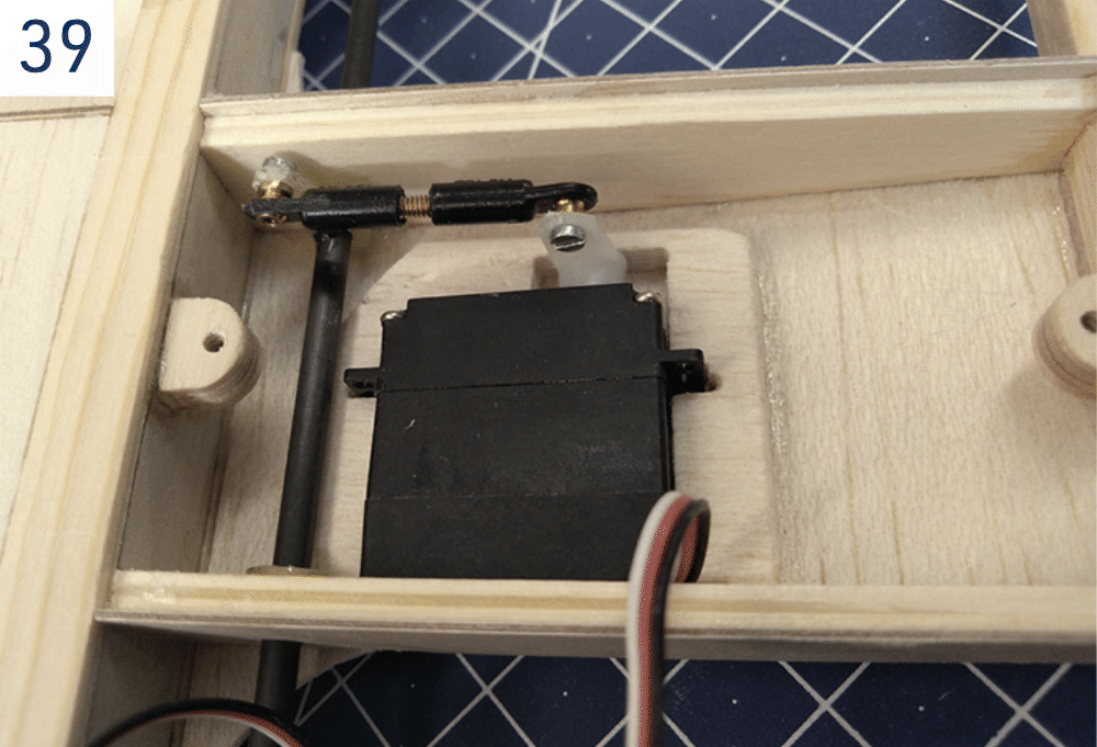
- Refer to the Det. C on the building plan during the final airbrake servo installation. Link the servo horn and the W36 torsion bar lever with two ball links joined together with an M2 threaded rod (saw off the head of the supplied M2×10 mm screw).
- Once you check the servo can move freely within the required range, cyano the W36 lever to the W37 carbon torsion bar. (Fig. 39)
- With your radio on, set the airbrake servo to the „airbrake fully extended“ position. One at a time set the W22 and W23 airbrakes in the fully extended position (−24 mm), push the corresponding lever W35 to the airbrake and secure with a small drop of cyano to the W37 torsion bar. Take care the position of both airbrakes is exactly the same! Once satisfied, secure the joints of W35 and W36 levers with the W37 torsion bar using a sparse amount of epoxy.
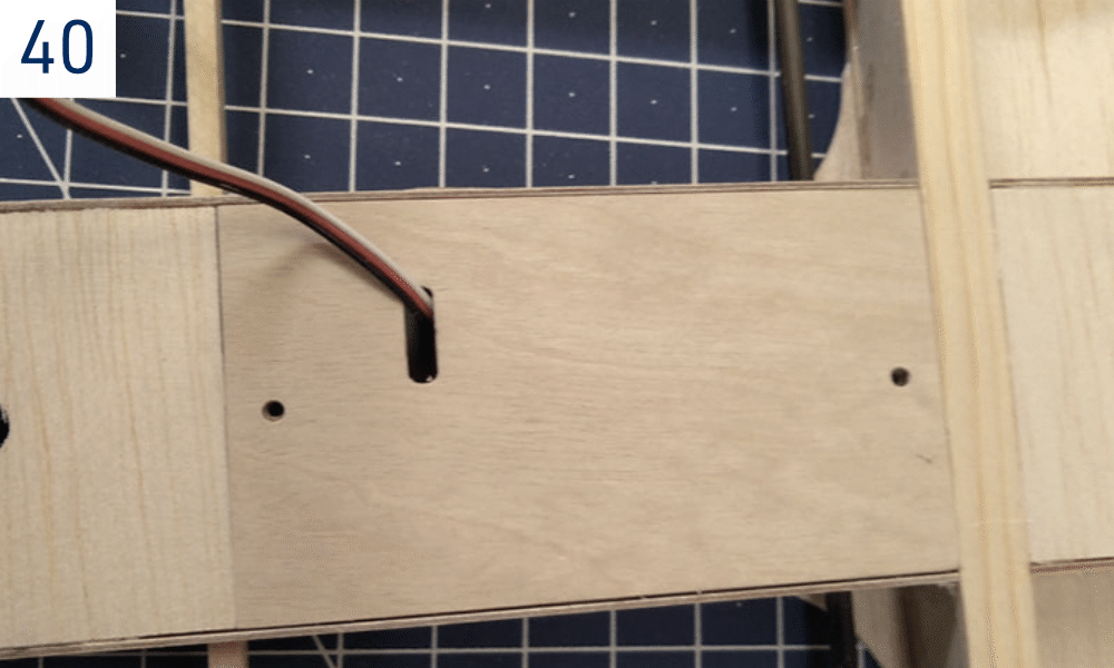
- Finally, cut an opening into the W25 hatch to allow free movement of the airbrake servo arm (if necessary) and secure it to the W32 holders. (Fig. 40)
Wing root ribs
- Glue the pairs of W31 magnets using 5 min epoxy into the openings in W6 and P1 ribs. Please check the polarity of the magnets first – they must attract each other.
Tow hook (glider)
- Install the tow hook to the pre-drilled holes in the F15 plate.
- Keep the recommended CG position 78–82 mm behind the wing leading edge.
- Set the tow hook 10 mm in front of the CG for the first flight.
- You have to loosen the front screw in order to move the tow hook.
Power system installation (electric version)
- Attach the motor to the firewall with suitable screws. Secure the ESC and flight battery in the nose with hook-and-loop fastening.
- Remove the propeller before checking motor rotation. Switch the transmitter on, then connect the flight battery. The motor must turn counterclockwise when viewed from the front.
- If rotation is incorrect, disconnect the flight battery before swapping any two motor wires, or change the ESC direction setting as its manual describes. Repeat the check without the propeller.
- Disconnect the battery and fit a Ø30mm spinner with folding blades matched to the motor and battery. Keep clear of the propeller whenever the battery is connected.
Pre-flight preparation
Centre of gravity and control throws
Measure the CG behind the wing leading edge at the root, with the model assembled and ready to fly. The nominal specification is 80 mm; the adjustment range is 78–82 mm.
Start with the CG at 78 mm. Do not move it behind 82 mm. Recheck the balance after changing the battery or adding ballast.
| Function | Setting |
|---|---|
| Rudder | ±13 mm |
| Elevator | ±13 mm |
| Airbrake | −24 mm |
| Airbrake → elevator mix | −2 mm elevator at full airbrake |
The airbrakes deploy upwards; the negative value follows the building plan’s notation. Confirm the elevator compensation direction against the plan and test it progressively at a safe height. Check that no linkage binds at full travel.
Flying
Be sure you are using fully charged batteries. Now (and before any further flight again) check the correct function of the whole radio equipment, motor and moving of control surfaces. Be sure any part of flight equipment cannot move during flight. We strongly recommend making a range check (see your radio instruction manual for details).
The first flight
Wait for a calm day with wind below 3 m/s. Fly only on a safe site as an RC club flying field. Glider will be very happy on your favourite slope on a calm day. The very light lift will allow perfect fine trimming out.
Glider
Switch your transmitter and then the receiver on and check all the working systems one more. Facing INTO the wind hold your transmitter in one hand; grip the model in the other hand near the centre of gravity. Hold it at head level and launch it with a smooth, positive push directly into the wind; wings level, nose slightly down. Your model should now glide in a long, flat and straight path without needing any help from you. Use the controls gently if necessary, and adjust the trim tabs until your Mirai glides the above-described way. After landing, check the position of the control surfaces; set the length of pushrods to bring back trim tabs on your transmitter to a neutral position if necessary (we strongly recommend doing it in any way). Check again the gliding of your Mirai.
Once the glide is trimmed, use a 100–150m towline with a pennant, or a bungee set matched to the model’s wingspan and flying weight. Have an experienced helper launch the model if possible.
Electric version
- Switch the transmitter on before connecting the flight battery and repeat the control checks. Have an experienced helper launch the model into the wind at full throttle. Allow it to gain flying speed before climbing; avoid a steep, stalled climb.
- Climb gently into the wind to a safe trimming height within the limits of the flying site. Check the powered flight, then reduce power to establish straight, level flight and switch the motor off to assess the glide.
- Trim and check the glide first. Compare powered flight with the trimmed glide when assessing motor thrust alignment. Make mechanical adjustments only after landing with the battery disconnected. Recheck the CG before changing motor downthrust.
Final fine-tuning
During the next flights trim out your Mirai to find optimal setting – safe climbing and good gliding – it is a compromise, of course. You might find it useful to program a spoiler → elevator mix (if your radio allows) that will eliminate the nose pitching when the spoiler is deployed. In general, the CG position should be located between 78–82 mm behind the wing leading edge. By moving the CG back you get better gliding performance whilst reducing the stability. It makes your model more sensitive on controls and increases the model reaction on thermal. The back CG position makes the model more difficult to fly and requires more attention from you, while a nose-heavy model is easier to fly but you will lack the performance. We recommend starting with the CG at 78 mm behind the leading edge. Beyond 82 mm the increasing lack of stability prevails over the gain of gliding performance. On windy days, you can improve the penetration of the glider version by putting additional ballast into the F20 ballast tube.
Enjoy your new Mirai, have a ball!
Assembly illustrations
Please note the pictures are just for illustration only – some show our prototype that might differ slightly from the actual, regular series production kits.

Appendix
Main parts
| Part | Quantity | Building plan no. | Material |
|---|---|---|---|
| Building plan 1:1 | 1 | ||
| Instruction manual | 1 | ||
| Sheet of stickers | 1 | ||
| Pushrod set | 2 | Plastic tube + 0.8 mm piano wire | |
| Tail boom | 1 | F22 | Carbon tube Ø18×10 mm |
| Pushrod holder + formers | 1+1 | Balsa 1.5 mm + 0.8 mm Plywood |
Bag no. 1 - small parts
| Part | Quantity | Building plan no. | Material |
|---|---|---|---|
| Adjustable tow hook w. M3 socket screw | 1 | Fibreglass + metal | |
| Magnet | 6 | F21, W33 | Neodymium 3×3 mm |
| Magnet | 4 | W31 | Neodymium 10×3 mm |
| Wing bolt M5 | 1 | Nylon | |
| Captive nut M5 | 1 | Aluminium | |
| Rudder horn | 2 | V11 | Fibreglass 1.5 mm |
| Wing outer panel alignment pin | 4 | P30 | Beech dowel Ø3 mm |
| Fuselage corner radius template | 1 | Lite Ply 3 mm | |
| Nose shape template | 1 | Lite Ply 3 mm | |
| Dihedral jig 7° | 1 | Lite Ply 3 mm | |
| Airbrake magnet holder | 2 | W29 | Lite Ply 3 mm |
| Fuselage hatch lock | 1 | F6 | |
| Kevlar thread | 1 | ||
| Carbon rod | 4 | V16 | Carbon rod Ø2 mm |
| Ruddervator servo tray | 1 | F23 | |
| Airbrake lever set | 1 | W34+W35+W36 | Fibreglass plate 1.5 mm |
| V-tail seat with pin | 1+1 | V8L/R, V9 | Lite Ply 3 mm, steel Ø1.5 mm |
| Ball link short M2 | 4 | ||
| Threaded coupler M2 | 2 | Brass M2/0.8 mm | |
| Airbrake link bolt M2 | 1 | M2×10 mm machine screw | |
| Tail skid | 1 | V12 | Balsa 3 mm |
Bag no. 2
| Part | Quantity | Building plan no. | Material |
|---|---|---|---|
| Nose block | 2 | F1 | Balsa 10 mm |
| Towhook plate | 1 | F15 | Plywood 1.5 mm |
| Wing bolt plate | 1 | F9 | Plywood 3 mm |
| Fuselage former | 1 | F7 | Plywood 3 mm |
| Fuselage former | 1+1+1 | F2, F8, F9 | Lite Ply 3 mm |
| Horizontal tail boom holder | 1 | F13 | Lite Ply 3 mm |
| Vertical tail boom holder | 1 | F14 | Plywood 3 mm |
| Fuselage cross-brace | 3 | F18, F19 | Lite Ply 3 mm |
Bag no. 3
| Part | Quantity | Building plan no. | Material |
|---|---|---|---|
| Wing rib | 2 | W3 | Lite Ply 3 mm |
| Wing rib | 4 | W6, P1 | Lite Ply 3 mm |
| Wing rib | 2 | W4 | Plywood 0.8 mm |
| Main spar shear webbing joiner short | 1 | W11 | Plywood 0.8 mm |
| Main spar shear webbing joiner long | 1 | W12 | Plywood 0.8 mm |
| Wing joiner bay plate | 2+2+2+2 | W14, W16, P25, P26 | Plywood 0.8 mm |
| Riblet with wing alignment pin | 1 | W1 | Plywood 3 mm |
| Riblet | 2 | W2 | Plywood 0.8 mm |
| Wing bolt plate | 1 | W10 | Plywood 2 mm |
| Wing joiner bay | 2+2 | W15, P22 | Plywood 5 mm |
| Wing centre sheeting | 1+1+1+1 | W18, W19, W28a, W28b | Balsa 1.5 mm |
| Airbrake bay reinforcement plate | 2 | W20 | Balsa 1.5 mm |
| Airbrake servo hatch | 1 | W25 | Plywood 1.2 mm |
| Winglet joiner | 2 | P29 | Plywood 1.5 mm |
| Airbrake servo hatch holder | 2 | W32 | Plywood 5 mm |
| Wing joiner 2 pieces | 2 | P32 | Carbon |
Bag no. 4 - V-tail
| Part | Quantity | Building plan no. | Material |
|---|---|---|---|
| Stabilizer | 2 | V1L/R | Balsa 3 mm |
| Ruddervator | 2 | V2 | Balsa 3 mm |
| Stabilizer tip | 2 | V3 | Balsa 3 mm |
| Stabilizer ribs | 2+2+2 | V5, V6, V7 | Balsa 3 mm |
| Carbon stabilizer reinforcement | 2 | V10 | Carbon 0.5×3 mm |
| Plastic tube | 4 | V14 | Plastic tube Ø3 mm |
| Stabilizer root rib | 1+1 | V4L/R | Plywood 1.2 mm |
| Stabilizer lock | 2 | V13 | Fibreglass 1.5 mm |
Bag no. 5
| Part | Quantity | Building plan no. | Material |
|---|---|---|---|
| Firewall | 1 | E2 | Plywood 3 mm |
| Balsa triangle stock | 4 | E4 | Balsa 8×8 mm |
| Spinner ring | 1 | E1 | Plywood 1.2 mm |
| Servo tray electric | 1 | E3 | Lite Ply 3 mm |
| Battery tray | 1 | E5 | Balsa 5 mm |
| Fuselage cross-brace | 3 | F18, F19 | Lite Ply 3 mm |
Bag no. 6
| Part | Quantity | Building plan no. | Material |
|---|---|---|---|
| Wing centre section rib | 6 | W7 | Balsa 1.5 mm |
| Wing centre section rib | 2 | W8 | Balsa 1.5 mm |
| Wing centre section rib | 4 | W9 | Balsa 1.5 mm |
| Wing outer panel rib set | 2 each | P3–P9, P12–P15 | Balsa 1.5 mm |
| Wing outer panel root rib | 2 | P2 | Balsa 5 mm |
| Wing outer panel end/Winglet root rib | 2+2 | P10, P11 | Balsa 5 mm |
| Winglet end rib | 2 | P16 | Balsa 5 mm |
| Wing centre section trailing edge | 1 | W17 | Balsa 5×20 mm |
| Wing outer panel trailing edge | 1+1 | P24R/L | Balsa 5×20 mm |
| Leading edge 1+2 pieces | 1+1+1 | W30, P20 | Balsa 5×5 mm |
| Wing centre section D-box sheeting | 1 | W24 | Balsa 1.5 mm |
| Wing outer panel D-box sheeting | 2 | P27+P28 | Balsa 1.5 mm |
| Wing centre section main spar | 2 | W26 | Spruce 2×8×690 mm |
| Wing centre section rear spar | 1 | W27 | Spruce 3×6×690 mm |
| Wing centre section main spar shear webbing | 1+1 | W13 | Balsa 5 mm |
| Wing outer panel main spar shear webbing | 2 | P21 | Balsa 5 mm |
| Wing outer panel main spar | 4 | P33 | Spruce 2×8×380 mm |
| Wing outer panel rear spar | 2 | P23 | Spruce 3×5×380 mm |
| Wing outer panel main spar (outer) | 4 | P34 | Balsa 2×8×260 mm |
| Wing outer panel rear spar (outer) | 2 | P31 | Balsa 3×5×200 mm |
| Wing gusset set | 1 | W38, P33 | Balsa 2.5 mm |
| Wing tip | 2 | P18 | Balsa 3 mm |
| Wing tip reinforcement | 2 | P19 | Balsa 3 mm |
| Winglet fairing | 2 | P17 | Balsa 10 mm |
| Airbrake | 1+1 | W22, W23 | Balsa 2.5 mm |
| Airbrake torsion bar | 1 | W37 | Carbon rod Ø3 mm |
| Wing outer panel diagonal brace | 1 | P34 | Spruce 3×5×200 mm |
Bag no. 7
| Part | Quantity | Building plan no. | Material |
|---|---|---|---|
| Fuselage side | 1+1 | F17L/R | Balsa 2 mm |
| Fuselage bottom sheeting | 1 | Balsa 2.5 mm | |
| Fuselage upper sheeting | 3 | Balsa 2.5 mm | |
| Tail boom fairing | 1+1 | F11, F12 | Balsa 8 mm |
| Fuselage side reinforcement plate (front) | 2 | F3 | Lite Ply 3 mm |
| Fuselage side reinforcement plate (rear) | 1+1 | F5L/R | Lite Ply 3 mm |
| Servo hatch | 1 | F16 | Balsa 2 mm |
| Ballast tube | 1 | F20 | Carbon tube Ø10 mm |