KAVAN Flix 850mm - Instruction manual
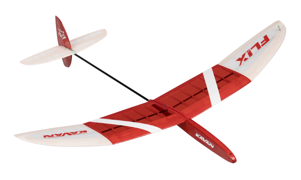
KAVAN Flix - kit
Introduction
The small discus launch RC glider (DLG) Flix has been designed with beginners in mind. This kit introduces classic balsa construction and covering with lightweight iron-on film or tissue. Some experience of building simple models is recommended. You will need some basic modeller’s tools, glues and dopes – you will find these handy with any of your future projects as well. Please make yourself familiar with the building plans and this manual before you actually start the assembly.
Before you start
- If you are new to model aircraft, ask an experienced modeller to check your completed model and help you with the first flights. Your model shop or local model flying club can help you find an instructor.
- Build the model according to these instructions. Do not alter or modify it, as this can make it unsafe or unable to fly. Take time to build everything straight, true and strong.
- Check the kit for missing or damaged parts before starting. Familiarise yourself with each component and contact your dealer immediately if a replacement is needed.
- Trial fit every part before gluing. Check that you have the correct part and that it fits properly; extra glue cannot compensate for a poor fit.
- Set the centre of gravity (CG) and control throws as described in Pre-flight preparation before the first flight. Incorrect balance can make the model unstable or unable to fly.
Check the contents and report missing or damaged parts before starting construction.
Safety precautions
This model is not a toy. Even though it is light and slow in flight, incorrect handling can cause injury or damage. Build, test and fly it responsibly, following the instructions, applicable model flying safety rules and common sense.
Use suitable tools and accessories in good condition. Install all parts correctly and check the model before the first and every subsequent flight. Do not fly a damaged model. Beginners should fly with help from an experienced modeller.
Children under the age of 14 must operate the model under adult supervision. Fly in calm weather or a light breeze at a safe site away from obstacles.
Features
- Small, high-performing glider kit
- Designed and manufactured in the Czech Republic
- Discus launched
- CNC pre-cut parts
- Controlled rudder and elevator
Technical specifications
| Parameter | Value |
|---|---|
| Wingspan | 850 mm |
| Length | 867 mm |
| Wing area | 12.98 dm² |
| All-up weight | 140–150 g |
Set contents
CNC-cut balsa and plywood parts, carbon wing-spar tubes, carbon tail boom, accessory set, sticker sheet, full-size building plan and instruction manual.
Recommended RC equipment
- At least a two-channel transmitter with a miniature receiver suitable for direct power from a 1S LiPo battery.
- Two KAVAN GO-02+ servos or similar 2–3g servos with approximately 0.5 kg·cm torque, suitable for the same supply voltage.
- A 1S LiPo receiver battery with a nominal voltage of 3.7 V and capacity of 350–450 mAh.
Recommended glues
You can use solvent-based modeller's glue (UHU® Hart etc.), water-resistant white glue (KAV56.9960 / KAV56.9961, BISON® Super Wood etc.) or CA (KAV56.9951 Power CA Thin, KAV56.9952 Power CA Medium, KAV56.9953 Power CA Thick) with an accelerator (KAV56.9983 KAVAN PRO Accelerator CA Spray), and 5min epoxy (KAV56.9962 KAVAN Epoxy 5min).
Covering material
Oralight® iron-on film or 13–17 g/m² covering tissue (KAV524.13 Japan paper white 13 g/m²)
Recommended dopes
For tissue covering, use KAVAN Standard adhesive dope (KAV56.9988), shrinking dope (KAV56.9986), protective dope (KAV56.9989) and matching thinner (KAV56.9992 / KAV56.9992A). KAVAN Color coloured shrinking dopes (KAV56.9987.x) may also be used.
Tools and accessories
You will need a perfectly flat building board (at least 300×700 mm), modeller’s knife (KAV66.770) with no. 11 blades, razor saw, drill with a drill bit set including a 3.5mm bit, model hobby sealing iron (KAV66.8335), sanding blocks with No. 120, 180, 240 and 360–400 grit sandpaper, modeller’s pins (KAV66.0355), scissors, flat and round fine file, soft flat (1/4"–3/8") brush, thin clear plastic film to protect the building plan (a large PE bag cut in half will work), paper masking tape, clear sticky tape 10–20 mm.
Main section
Building plan and illustrations
Use the full-size plan supplied with the kit to identify parts and check their alignment. The numbered drawing references below correspond to the original instruction PDF.
Use glues, dopes and thinners in a well-ventilated area, away from flames, sparks and other ignition sources. Follow the product labels and avoid inhaling vapours or sanding dust.
Assembly
Lay the building plan on the building board and put a sheet of a thin clear plastic film to protect the building plan.
Before applying the glue, please always double check the correct size, shape and alignment of the particular part.
Fuselage
- Use thick CA to glue together parts T1+T13, T2+T3 and T2+T3A. (Fig. 1)
- Use thick CA to glue together parts T13+T11. (Fig. 2)
- Sand the assembled parts smooth carefully. (Fig. 3)
- Glue the servo tray T12 into the fuselage centre T13. Once the glue has set sand the surface smooth. (Fig. 4)
Note
The openings in parts T3A and T12 are to match the KAVAN GO-02+ servos. If you are using other servos, it may be necessary to modify their (T3A and T12) shape or make new ones to fit your servos. In any case, test whether your servos can be inserted into the fuselage before gluing the T4 and T4A side panels (see the side-panel fitting drawings) in place.
- Insert pins T6 and T8 into part T13 so that they protrude equally on both sides. Then glue parts T9 to both sides of T13 with dispersion glue. (Fig. 5)
- Glue parts T3, T3A and T5 with white glue as shown. (Fig. 6)
- Glue T7 with white glue to both sides of the fuselage as shown. (Fig. 7)
- Sand the nose to the profile shown, preserving the 8mm dimension indicated in the drawing. (Fig. 8)
- Glue parts T4A (on the right side) and T4 (on the left side) to the fuselage with white glue. After securing with clamps, remove the hatch T4B from part T4. Then use a damp cloth to remove any glue residue in the corners. (Fig. 9)+(Fig. 10)
- Sand the fuselage smooth, round the edges and the tip of the fuselage and sand the rear part according to the plan. The shape is marked on the drawing. (Fig. 11)
- Insert the T10 part into the fuselage groove. It must be easy to insert; if it does not slide freely, sand the T10 carefully until it fits without resistance. (Fig. 12)
Now you can sand the entire fuselage with fine sandpaper No. 360–400 and cover it with a thin Oralight® iron-on film, thin paper (10–14 g/m²) or non-woven fabric (Vlies) or just paint it twice with a protective dope.
Tail
Lay the building plan on the building board and put a sheet of a thin clear plastic film to protect the building plan.
- Insert the S6 and S7 stiffeners into the S4 fin and glue them with thin CA. (Fig. 13)
- Cut the fin and rudder ribs from the supplied 2×3 mm balsa stick to the correct length and glue them in place with white glue. (Fig. 14)
- Sand the glued rudder into a wedge shape by 1 mm as shown in the picture; round the leading edge of the fin. (Fig. 15)
- Chamfer the leading edge of the rudder so that a deflection of at least 12 mm to the side is possible. (Fig. 16)
- Insert the V6 reinforcement into the horizontal stabilizer V1 (with the hole forward) and glue it with thin CA. Cut the stabilizer and elevator ribs from the supplied 2×3 mm balsa stick to the correct length and glue them in place with white glue. (Fig. 17)
- Insert the V4 coupling into the elevator V3 and glue it with thin CA. (Fig. 18)
- Sand off the balsa bridge on the leading edge of the elevator. (Fig. 19)
- Sand the elevator into a wedge (as you did with the rudder). (Fig. 20)
- Finally, cut through the connecting bridge on the trailing edge. Place the elevator on a flat surface to make sure that both halves are flush and its leading edge is straight. (Fig. 21)
- Round off the leading edge of the stabilizer, chamfer its trailing edge so that the elevator can be deflected downwards by at least 12 mm. (Fig. 22)+(Fig. 23)
Bevel the stabilizer’s trailing edge; leave the elevator edge intact to avoid weakening the V4 joiner.
Wing
Lay the building plan on the building board and put a sheet of a thin clear plastic film to protect the building plan.
- Cut out the ribs K11 to K12U as shown. DO NOT BREAK THEM OUT, CUT THEM OUT! (Fig. 24)
- Connect the ribs K11, K12 and K12U by inserting the plastic tubes P1. DO NOT GLUE! (Fig. 25)
- Pin the leading edge K14 to the plan protected by the plastic film and glue the wing tips K16 to it with thick CA. (Fig. 26)
- Glue the trailing edges K13 to the wing tips K16 with thick CA and pin them to the plan. Then glue the prepared ribs K11, K12 and K12U in place. (Fig. 27)
- Cut out the individual ribs K1 to K9 and insert them one by one into the positions marked on the plan. Place each rib according to its number, which corresponds to the numbering on the plan. (Fig. 28)+(Fig. 29)
- Glue the individual ribs with thin CA as shown. (Fig. 30)
- Apply thin CA to the corners at the leading and trailing edges as well. (Fig. 31)
- Glue the balsa wing tip plate K15 with thick CA as shown in the picture. (Fig. 32)+(Fig. 33)
- Cut the end of the balsa wing tip with a knife. (Fig. 34)
- Mark the centre of the leading edge with a pencil on the leading edge for better orientation when sanding. (Fig. 35)
- Shape the leading edge with a razor blade plane. (Fig. 36)
- Sand the bottom side of the wing. Sand in the chordwise direction shown, between the leading and trailing edges, without pressure; do not sand along the span, this will prevent unwanted under-sanding of the ribs. (Fig. 37)
For easy sanding of the wing, we recommend sticking 120 grit sandpaper onto a board measuring approximately 150×900 mm.
- Apply paper masking tape to the top side of the wing to prevent unwanted under-sanding of the ribs. Then sand the trailing edge. (Fig. 38)
- Apply paper masking tape to the top side to prevent unwanted undercutting of the ribs when sanding the leading edge. (Fig. 39)
- Sand the leading edge; use the touch templates as shown in the profile-template drawing below to check that its shape is correct. Sand lightly to keep the shape right. Use 120 grit sandpaper. (Fig. 40)+(Fig. 41)+(Fig. 42)
- Carefully cut the sanded wing into individual parts. (Fig. 43)
- Place the Pk1 bevel jig on the edge of the worktop and sand the bevels on the individual parts of the wing as shown in the picture. (Tip: After sanding, use these parts to put together the balancing jig. Glue two Pk1 plates in the middle of the P60×60 plywood plate so that there is a 30 mm gap between them.) (Fig. 44)
- Connect the centre part of the wing with the outer wing panel using paper tape and check the correct dihedral as shown in the picture. (Fig. 45)+(Fig. 46)
- Connect the wing halves with paper tape and check the correct dihedral according to the picture. (Fig. 47)
- Round the end of the carbon tube K214 with sandpaper. (Fig. 48)
- Bevel one end of the carbon tube K176 over the 10mm length shown in the drawing. (Fig. 49)
- Insert the carbon tube K176 into the right and left wing panels with the bevelled side up to the position shown in the drawings below, so that it is recessed into the root rib by 2 mm. (Fig. 50)+(Fig. 51)
- Insert the carbon tube K214 into the left and right centre parts of the wing so that it is recessed into the end and root ribs by 2 mm. (Fig. 52)
- Glue the K18 parts to the bottom and top of the groove in the wing tips, apply thin CA to the joint, spray with activator and sand the wing tips smooth. (Fig. 53)
- First glue the wing centre and the outer panel to the dihedral. Coat the contact surfaces of the ribs and the S1 connector with 5min epoxy, position the parts as shown, place plastic foil under the joint, secure the centre with tape and support the wing panel with a block of the required height. Check the correct dihedral of 45 mm. Immediately remove any excess glue squeezed out of the joint by wiping it with a paper towel moistened with rubbing alcohol. Then join the two centre panels in the same way, setting the 40mm dihedral measurement at the outer end of the raised centre panel as shown, rather than at the wingtip. (Fig. 54)+(Fig. 55)+(Fig. 56)
- Sand the glued joints smooth. (Fig. 57)
- Apply strips of self-adhesive tape on the fuselage as shown to prevent the wing from sticking to the fuselage. Insert the T10 part into the fuselage and screw it with the M3×16 screw in place. (Fig. 58)
- Place the wing on the T10 holder and check that it fits well to the fuselage and that it can be positioned on the fuselage with symmetrical dihedral on both sides. Once you are satisfied, apply 5min epoxy to the contact surface of the T10 part, place the wing and secure it with pins. Before the glue hardens double check that the wing is placed symmetrically on the fuselage. (Fig. 59)
Covering
Thoroughly sand the surface of all parts with No. 360–400 sandpaper and carefully vacuum all the dust (the iron-on film does not stick well to a dusty surface; the dust also contains hard grains released off the sandpaper capable to ruin the smooth non-sticking coating of your sealing iron quickly).
Use lightweight Oralight® iron-on film for the wing and tail. Follow the film manufacturer’s tacking and shrinking temperatures; avoid excessive heat on the light structure.
For tissue covering, use the method described in the Vinx manual, while retaining the Flix geometry and washout specified here.
Iron-on film covering
- Rudder and fin: Place the film on the bottom side, tack it to the frame with the tip of your iron first and then iron it down; then cut the film along the edges. Proceed in the same way with the top cover, then set your iron to the film manufacturer’s shrinking temperature and shrink the entire cover smooth. (Fig. 60)
- Connect the rudder and fin with a strip of clear self-adhesive tape (special tape for hinges from a model shop or 3M/Scotch Crystal® tape from a stationery store) and create a hinge as shown in the picture, aligning the parts edge to edge, joining them with tape along the entire length of the joint and bending the tape to create a functional, freely movable hinge. Fold the rudder back and apply the second strip on the opposite side as shown. (Fig. 61)
- Horizontal stabilizer and elevator: Place the film on the bottom side, tack it to the frame with the tip of your iron first and then iron it down; then cut the film along the edges. Proceed in the same way with the top cover, then set your iron to the film manufacturer’s shrinking temperature and shrink the entire cover smooth. (Fig. 62)
- Connect the horizontal stabilizer and elevator on the top with a strip of clear adhesive tape and create a hinge as shown in the picture, aligning the parts with their edges together, joining them with tape along the entire length of the joint and bending the tape to create a functional, freely moving hinge. Fold the elevator back and apply the second strip on the underside as shown. (Fig. 63)
- Wing: Prepare iron-on film for the bottom side of the right half of the wing with an overlap of about 1 cm around the outline. Make two holes in each rib with a pin so that the cover does not puff up when shrinking. Place the film on the underside of the outer wing panel, tack it to the frame with the tip of your iron first and then iron it down. (Fig. 64)
- Prepare iron-on film for the bottom of the left half of the wing with an overlap of about 1 cm around the outline. Make two holes in each rib with a pin. Place the film on the underside of the outer wing panel, tack it to the frame with the tip of your iron first and then iron it down. (Fig. 65)
- Trim the excess film cleanly around the edges and iron it so that there are no burrs anywhere. (Fig. 66)
- First, iron on the cover of the left and right wing outer panels. Prepare an iron-on film with an overlap of about 1 cm around the outline. Place the film on the top side of the wing panel, tack it to the frame with the tip of your iron first and then iron it down. (Fig. 67)
- Trim the excess film outside the trailing edges. Iron the leading edge. Iron the film on the trailing edge with an overlap to the underside. (Fig. 68)
- Then iron on the left and right centre parts of the wing. Prepare an iron-on film with an overlap of about 1 cm in width and 5 mm in length. Place the film on the top of the left centre, tack it to the frame with the tip of your iron first and then iron it down. Cover the right centre in the same way. (Fig. 69)
- Cut off the overlapping film outside the trailing edges. Iron the leading edge. Iron the film on the trailing edge with an overlap to the bottom. (Fig. 70)
- On the wing, create the washout so that the trailing edge of both outer wing panels is 2 mm higher at the wing tips than at their roots. Check on a flat board on which you place the entire wing. Heat the upper and lower covering of the given part with an iron, twist to the desired washout (preferably a little more, the wing panel is flexible – once you release the grip after cooling, the twist will decrease somewhat) and hold in the twisted position until it cools down. Make sure that the washouts on both wing outer panels are identical. (Fig. 71)
Finishing the tail
- Glue the fibreglass rudder horn P1 into the rudder – cut through the film covering the hole for the horn. Lightly sand the horn so that it fits into the groove as shown in the picture, and then glue it with 5-minute epoxy in place. Immediately wipe off any excess glue with a paper towel moistened with rubbing alcohol. (Fig. 72)
- Glue the M2 nut to the top of the horizontal stabilizer by first carefully tapping it into place with a hammer and then securing it with a drop of thin CA. (Fig. 73)
- Glue the fibreglass elevator horn P1 into the elevator – cut through the film covering the hole for the horn on the bottom side of the elevator, lightly sand the horn so that it does not protrude and fits into the groove like the rudder lever, and then glue it with 5-minute epoxy in place. (Fig. 74)
Finishing the wing
- Stick the paper masking tape along the left and right sides as shown in the picture at a distance of 1 mm from the T10 holder. Apply white glue to the resulting corner. Wipe off the excess glue with your finger, then remove the tape and let the glue set. (Fig. 75)
- Cut through the film covering the hole for the pin (for right-handed people on the left wing tip and for left-handed people on the right wing tip). Round the ends of the pin with sandpaper and soak them with thin or medium CA so that the ends do not fray and there is no risk of a carbon splinter getting stuck in your finger. Insert the pin symmetrically into the hole in the wing. (Fig. 76)
- Glue the pin on both sides with thin CA and spray with activator. (Fig. 77)
Finishing the fuselage
- Screw the horizontal stabilizer to the tail boom T15 with an M2×10 screw and align it so that the dividing line between the stabilizer and the elevator is perpendicular to the boom. Apply 5min epoxy to the inner part of the boom tube and the S6 reinforcement of the fin and insert the fin into the boom. Slide the Ps1 alignment jig onto the fin, press it against the horizontal stabilizer and hold until the glue hardens. (Fig. 78)
- After gluing the fin to the tail boom, attach part V5 to the horizontal stabilizer and glue it with thin CA. Apply one drop each at points 1–6 marked in the picture. (Fig. 79)
- Screw the K bracket onto the T4B receiver compartment hatch using a 1.6×6 mm screw. Insert the magnet and coat the hole in the fuselage with 5min epoxy. Then insert the hatch with the magnet into the fuselage so that the magnet is seated exactly. After the glue has hardened, remove the cover from the fuselage. (Fig. 80)
- Insert the BW push rod outer tubes into the fuselage as shown in the picture. (Fig. 81)
- Insert the Ø0.6 mm piano wires into the outer tubes. (Fig. 82)
- Insert the carbon tail boom with the empennage into the fuselage. Insert the push rod tubes into the carbon tube and slide the entire tail boom inside; the push rod tubes with wires serve as a guide for precise insertion of the tail boom. Screw the wing onto the fuselage; check its symmetric alignment with respect to the horizontal tailplane. (Fig. 83)+(Fig. 84)
- Once satisfied, glue the tail boom to the fuselage with medium CA and spray with CA activator to harden it. (Fig. 85)
- As shown in the picture, create a hinge for the receiver compartment hatch using two strips of clear sticky tape. Use two strips next to each other, each 15–20 mm wide, so that each extends approximately 20 mm over the fuselage and the hatch. (Fig. 86)
- Close the hatch and secure it with one strip of 15–20 mm wide adhesive tape as shown in the picture. (Fig. 87)
- Carefully sand off the servo mounting lugs as shown in the picture so that the servos can be inserted into the prepared tray in the fuselage. (Fig. 88)
- Test whether the servo can be inserted into the tray in the fuselage; adjust the tray if necessary. Pull the servo out of the fuselage using needle-nose pliers (grab them as shown in the picture). (Fig. 89)
- Prepare the servo arms according to the pictures. Attach the push rod connectors Tb1 to the arms so that they rotate easily, but at the same time have no play (do not wobble). (Fig. 90)
- Prepare the piano wire push rods Ø0.6 mm according to the drawings, observing the 10mm clearances shown at the tail linkages; insert them into the holes in the control horns and into the guide tubes in the fuselage. (Fig. 91)+(Fig. 92)+(Fig. 93)
- Set the servo to neutral (centre) position with your radio on (or with the help of a servo tester), attach the servo arm and insert the servo into the fuselage. Insert the rudder push rod through the push rod connector Tb1, secure the rudder in the centre position and tighten the setting screw of the push rod connector. Then cut off the excess part of the push rod. Secure the servo in place with a few drops of hot melt glue. (Fig. 94)
- Install the elevator servo and push rod in the same way. (Fig. 95)
- Install the receiver and the receiver 1S LiPo battery 350–450 mAh into the fuselage according to the pictures. Soak the parts of the fuselage to which you will stick the self-adhesive foam tape or Velcro for attaching the receiver and battery with thin CA first. (Fig. 96)+(Fig. 97)
Pre-flight preparation
Centre of Gravity (CG)
- Support the model at the centre of gravity and, if necessary, add supplied ballast in the nose ballast compartment. The centre of gravity should be 75 mm behind the leading edge of the wing and the nose of the model should be pointing slightly towards the ground. Seal the ballast compartment opening with a strip of clear self-adhesive tape. (Fig. 98)
Recommended control throws
- Since the model flies in two significantly different modes – high-speed takeoff and relatively slow glide, it is ideal to program two flight modes on the transmitter (if it features flight modes). In both modes, the rudder and elevator have a travel rate of ±12 mm right/left or up/down. For the moment of launching, a switch or button on the transmitter should turn on the flight mode with the rudder fixed deflection in the direction opposite to the direction of the throw (for a right-handed person who throws the model in a left swing into a right turn, the rudder is to be deflected to the right). For our prototype and the swing of our right-handed test pilot, the optimal deflection was 8 mm to the right – the size depends on the execution of the takeoff and the strength of the swing. (Fig. 99)
| Start | Gliding | Expo | |
|---|---|---|---|
| Rudder | deflected 8 mm against the direction of the throw | ±12 mm | 20 % |
| Elevator | ±12 mm | 45 % |
The recommended exponential rates are for reducing sensitivity around neutral (different brands of transmitters may use negative or positive values to achieve that – refer to the instruction manual of your RC set).
Flying
Be sure you are using fully charged batteries. Now (and before any further flight again) check correct function of whole radio equipment and movement of the control surfaces. Be sure any part of flight equipment cannot move during flight. We strongly recommend making a range check (see your radio instruction manual for details).
- The first flight: Choose calm weather or a light breeze below 3 m/s. Fly only on a safe site as a RC club flying field. Glider will be very happy on your favourite slope on a calm day. The very light lift will allow perfect fine trimming out. (Fig. 100)
Switch your transmitter and then the receiver on and check all the working systems one more time. Facing INTO the wind hold your transmitter in one hand; grip the model in the other hand near the centre of gravity. Hold it at head level and give the model a fairly powerful push exactly into wind; wings level, nose slightly down. Your model should now glide in a long, flat and straight path without needing any help from you. Use the controls gently if necessary, and adjust the trim tabs until your Flix DLG glides above described way. Now check the position of control surfaces; set length of pushrods to bring back trim tabs on your transmitter to central position if necessary (we strongly recommend doing it in any way). Check again gliding of your Flix DLG.
You can also fine-tune gliding flight by adjusting the horizontal stabilizer (recommended):
- The model descends too steeply – the model has too small an angle of incidence. Insert a thin shim under the rear of the horizontal stabilizer.
- The model repeatedly pitches up and down – the angle of incidence is too large. Insert a thin shim under the leading edge of the horizontal stabilizer.
Now you are ready to make your first discus launch.
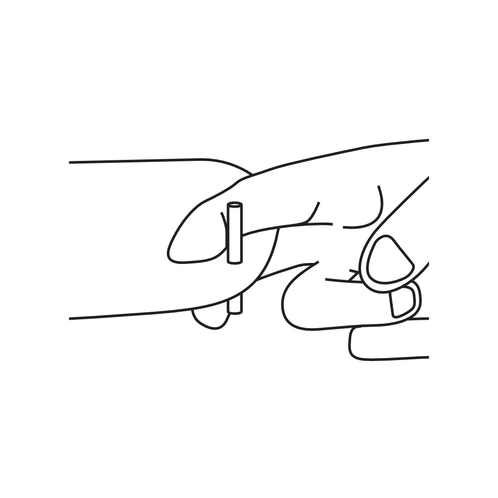
Discus launch
The discus launch allows your model to reach quite a high altitude without much effort. As it is with any „sports performance“, it will require some training to do it right – our step-by-step manual makes it easy. We will describe the procedure for a right-handed pilot; with the launching pin attached to the left wingtip. The „left-handed“ procedure is the mirror image.
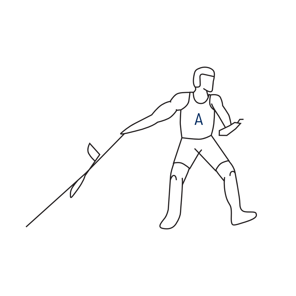
Position A – getting ready
Your right index finger and middle finger should be wrapped around the launch pin at the left wing tip. Your thumb is to be gently pressed against the leading edge of the wing. Stand with your left shoulder into the wind and the right wing tip pointing at ca 45° angle to the ground. Hold the transmitter in your extended left hand.
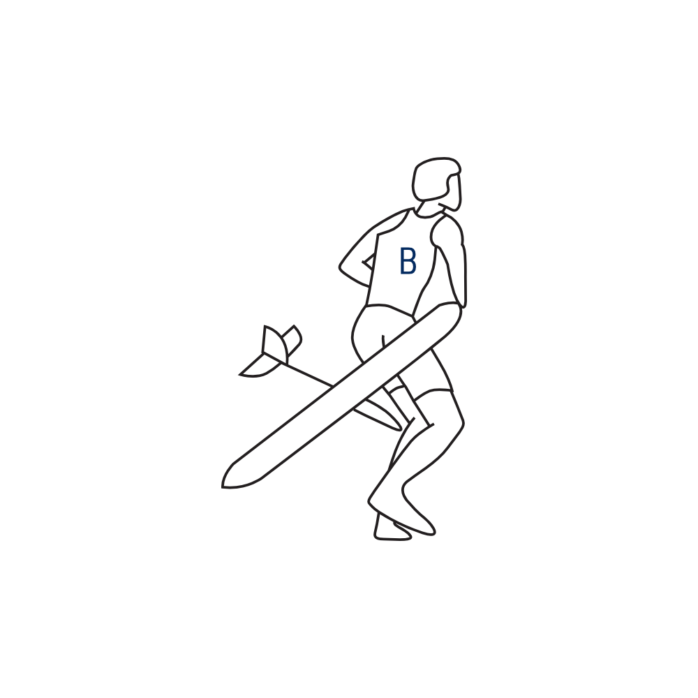
Position B – the first step
Take a long step with your left foot pulling the Flix up and forward with your right arm.
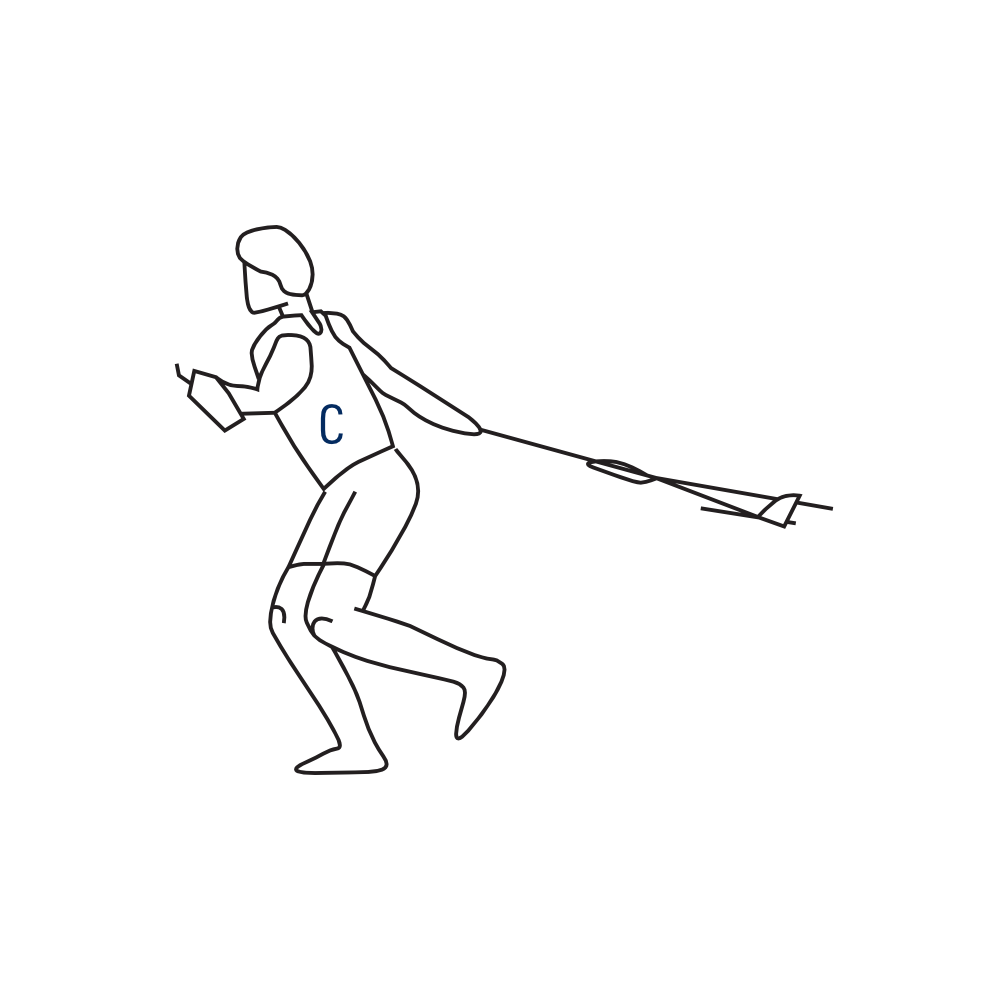
Position C – rotation
Step into the left-hand rotation with your right foot, keeping the Flix level and your right arm extended.
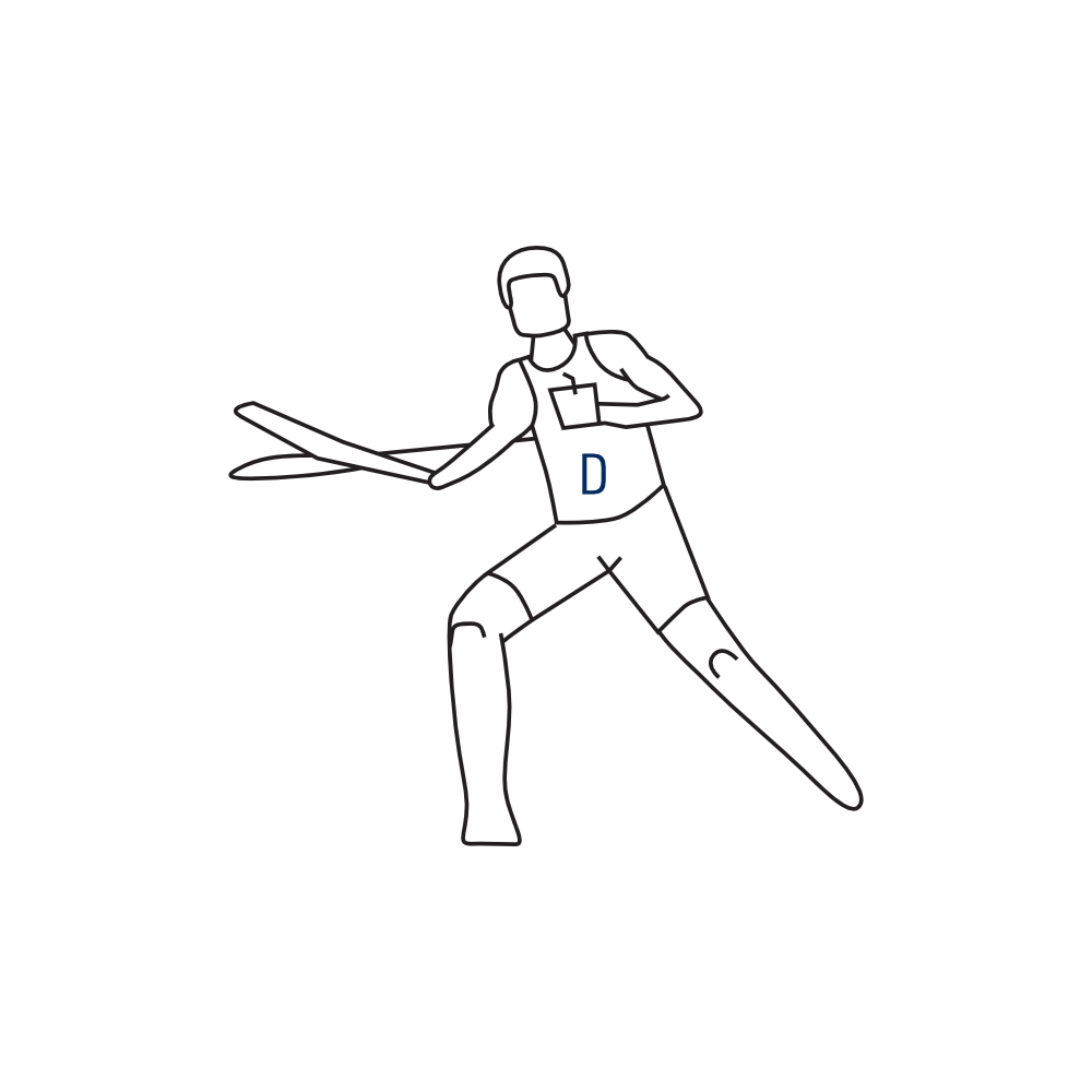
Position D – continued rotation
The second half of the rotation – the part that is most important for a good launch. Do not use too much arm in this section. Just let the swing of your torso speed the Flix up.
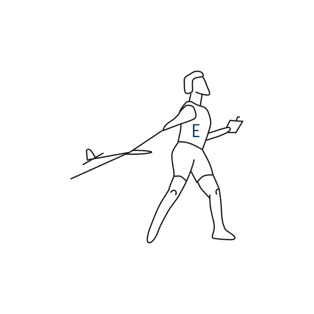
Position E – release
By this time in the launch the plane will be trying to climb on its own. Just release your fingers and let the plane fly out of your hand directly into the wind.
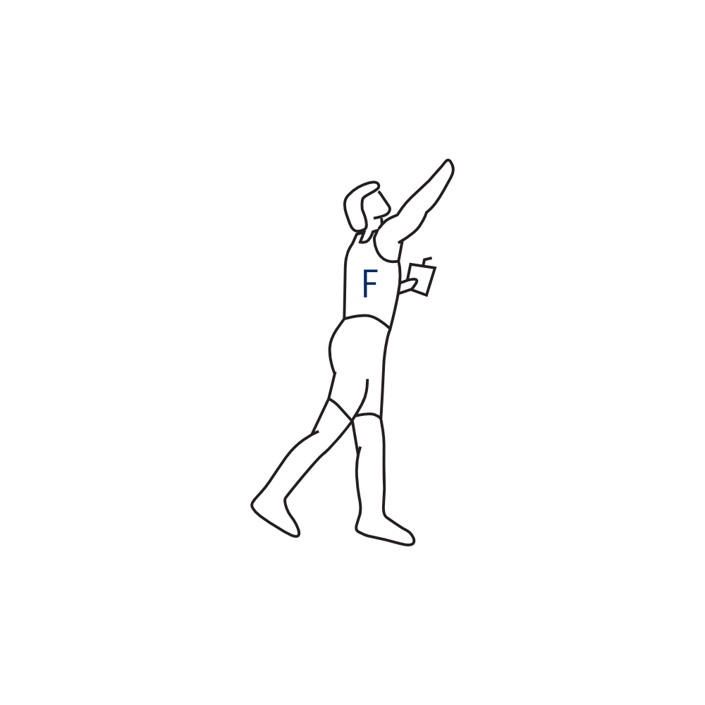
Position F – taking control
Catch your balance. Watch your Flix climb whilst getting hold of your radio and be ready to control your model.
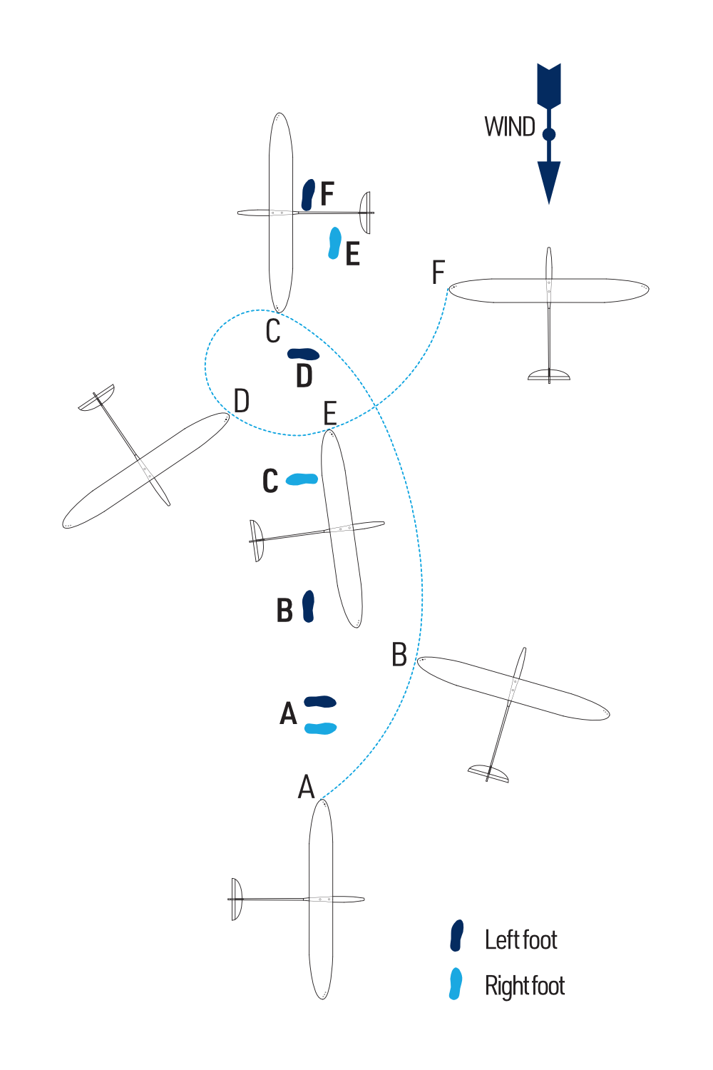
The plane will climb after release – the climb angle should be shallow at first. Once you are well acquainted with the discus launch you can use more force and increase the launch angle up to 60–80°. When completely familiar and comfortable you can add two quick steps before starting the turning sequence to get some extra speed and energy.
When the plane has slowed almost to the point of stopping push full down elevator to achieve level flight. When this is done at the right moment the plane will go into horizontal flight with just enough airspeed to maintain a gentle glide. If it is done too early the plane will pitch up her nose dangerously after a short dive. If it is done too late the plane will stall.
Have a ball; enjoy your new Flix DLG!
Appendix
Parts identification
Identify the supplied parts by the printed labels and full-size plan. The following layouts reproduce the grouping used in the original PDF.


Assembly illustrations


