KAVAN Der kleine Falke 1240mm - Instruction manual
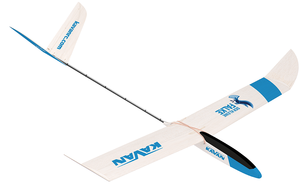
KAVAN Der kleine Falke A1 - kit
Introduction
The Der kleine Falke (Little Falcon) is a beginner's glider kit that can be built as a free-flight F1H (A1) model, an RC glider or an electric-powered RC glider. Choose the version before starting construction. You will need basic modelling tools, glues and protective dope, which will also be useful for future projects. Read this manual and study the supplied building plan thoroughly before starting assembly.
Before you start
- If you are new to model aircraft, ask an experienced modeller to check your completed model and help you with the first flights. Your model shop or local model flying club can help you find an instructor.
- Build the model according to these instructions. Do not alter or modify it, as this can make it unsafe or unable to fly. Take time to build everything straight, true and strong.
- Check the kit for missing or damaged parts before starting. Familiarise yourself with each component and contact your dealer immediately if a replacement is needed.
- Trial fit every part before gluing. Check that you have the correct part and that it fits properly; extra glue cannot compensate for a poor fit.
- Use the centre of gravity (CG) position marked on the supplied building plan. Balance the model before the first flight as described in Pre-flight preparation.
Your dealer cannot accept kits for return if construction has begun.
Safety precautions
This model is not a toy. Even though it is light and slow in flight, incorrect handling can cause injury or damage. Build, test and fly it responsibly, following the instructions, applicable model flying safety rules and common sense.
Use suitable tools and accessories in good condition. Install all parts correctly and check the model before the first and every subsequent flight. Do not fly a damaged model. Beginners should fly with help from an experienced modeller.
Children under the age of 14 must operate the model under adult supervision. Fly in calm weather or a light breeze at a safe site away from obstacles.
Features
- Suitable as a first glider
- Designed and manufactured in the Czech Republic
- Laser-cut parts
- Easy to build
- Good flight characteristics
Technical specifications
| Parameter | Value |
|---|---|
| Wingspan | 1240 mm |
| Length | 870 mm |
| All-up weight, free-flight model | Approximately 160 g |
| Minimum mass for F1H (A1) | 220 g |
| All-up weight, RC glider | Approximately 220 g |
| All-up weight, electric-powered RC glider | 300–320 g |
Set contents
Laser-cut balsa and plywood parts, pre-shaped wing and tail parts, carbon tail boom, control linkages and small accessories, sandpaper, ballast, wing retaining rubber bands, tow hook, stickers, building plan and instruction manual.
Recommended glues
Use a solvent-based modelling glue (UHU® Hart, Kanagom or similar), water-resistant white glue (KAV56.9960 / KAV56.9961, BISON Super Wood or similar), or medium cyanoacrylate glue (KAV56.9952).
Recommended dopes
Use KAVAN protective dope (KAV56.9988) and its matching thinner (KAV56.9992 / KAV56.9992A).
Tools and accessories
Prepare a perfectly flat building board that accepts pins (at least 150×700 mm), a modelling knife (KAV66.770) with no. 11 blades, a fine razor saw or fretsaw, a builder's square, a drill with Ø1.5mm, Ø2.5mm and Ø5.5mm bits, sanding blocks or sponges with 180–200 and 360–400 grit sandpaper, flat and round needle files, modelling pins (KAV66.0355), scissors and a soft flat 1/4"–3/8" brush. Protect the building plan and board with thin clear plastic film; a large polyethylene bag cut open is suitable.
Main section
Choose the version
Free-flight glider
For F1H (A1) competition, add ballast so the completed model weighs at least 220 g. Place additional competition ballast at the CG to preserve balance. Check the current F1H rules before entering a competition.
RC glider
Install a miniature receiver and two micro servos weighing 5–6 g each. Use a transmitter with a V-tail mix to control rudder and elevator with the two tail surfaces. The all-up weight should be approximately 220 g. This version is suitable as a first RC model with help from an experienced pilot.
Electric-powered RC glider
A small brushless motor with a pusher propeller can be installed on a pylon above the wing. The all-up weight should be approximately 300–320 g.
The source manual does not specify the motor, propeller, ESC, flight battery, pylon installation or numerical control throws for an RC conversion. Select compatible equipment and follow its instructions, with help from an experienced modeller. Check the CG and all controls before flying the completed version.
Building plan
Use the supplied full-size plan to identify the numbered parts, wing profile, dihedral, V-tail assembly, hinge positions and CG mark. References below point to this plan. (Fig. 1)
Assembly
Wing
- Carefully sand the entire surface of the wing leading edge halves no. 1 and no. 2. Sand the leading edge to the shape shown at the top left of the building plan. (Fig. 1)
- Glue the wing spar no. 3 to the wing leading edge no. 1 together on a flat building board protected with a sheet of thin plastic film. Check the spar orientation against the wing section at the top left of the plan. Test fit the parts together before applying the glue. Sand to fit if necessary.
- Once the glue has cured sand the bottom side of the no. 1 and no. 3 parts perfectly flat.
- Support the wing leading edge with a suitable stick and glue the wing trailing edge part no. 4 to it.
- Once the glue has cured sand the upper side of the wing half smooth.
- Glue the no. 8 stick to the outer end of the wing half. Once the glue has cured sand it flat to match the wing surface. Build the other wing half in the same manner.
- Glue together parts no. 5 and no. 6 in order to make the wing joiner.
- Insert the wing joiner into the notch in the wing; attach the wing halves together (outer ends supported to obtain the 35mm dihedral shown on the building plan) bevel and sand the roots of the wing halves to match each other perfectly. (Fig. 1)
- Once satisfied, glue the wing joiner into one of wing halves. Let this joint dry. Then apply a generous coat of glue to the other wing half and attach them together carefully keeping the correct wing dihedral.
- Glue together the two no. 9 parts of the wing outer panels. Sand the joint smooth and then glue the wing panels to the wing centre section carefully keeping the correct dihedral.
- Glue the wing trailing edge reinforcement plate no. 7 in place.
- Apply a light coat of thinned protective dope to the entire wing. When dry, lightly sand all doped surfaces with the fine sandpaper. Repeat twice more. Sand lightly once every coat has dried. Apply the stickers.
Fuselage and tail
- Glue the fuselage formers no. 18–22 square to the fuselage baseplate no. 10.
- Glue the no. 34 upper longerons to the formers.
- Glue the nose plates no. 11–13 one by one in place.
- Glue the rear plates no. 28–33 one by one in place.
- Glue the no. 41 lower longerons in place.
- Sand the both sides of the fuselage smooth.
- Glue the no. 23 fuselage side plates in place.
- Glue the no. 14 upper plate in place.
Caution
Apply the glue ONLY in the front on the top of the no. 13 nose plate and ONLY tack glue the no. 14 plate in the rear (near the wing retaining dowel, at former no. 20).
- Glue the no. 15–17 upper plates in place.
- Cut and sand smooth the fuselage in order to create nice smooth curves.
- Drill through the openings for the wing fixing dowels using Ø2.5mm drill bit. Glue the dowels in place.
- Use a fine razor saw to cut through the no. 15 and no. 14 plates in the laser scribed line in the nose. Remove the canopy carefully and glue the no. 27 alignment pin along the front edge of the no. 14 plate. The no. 27 pin overlaps the front edge of the no. 14 plate securing the front of the canopy in place. Use the marked line on no. 27 to set this overlap.
- Bind the wing to the fuselage using supplied rubber bands. Now sand the rear bottom part of the canopy to match the curve of the wing.
- Glue the no. 24 inner tow hook plate to the bottom of the fuselage. Take care the pre-cut hole was in the longitudinal axis of the fuselage. Drill through the hole using Ø1.5mm drill bit. Glue the no. 25 lower tow hook plate concentric to the hole in place.
- Apply a light coat of thinned protective dope to the entire fuselage. When dry, lightly sand all doped surfaces with the fine sandpaper. Repeat twice more. Sand lightly once every coat has dried.
- Drill through the hole for the tubular tail boom using a Ø5.5mm drill bit in the rear end of the fuselage.
- Carefully cut the no. 37 control surfaces off the no. 36 V-tail stabilizers. Mark the centres of the connecting tabs between the no. 36 and no. 37 parts. Round the outer edges of the stabilizers (except for the roots) and control surfaces.
- Glue together the no. 36 V-tail stabilizers using the supplied jig (Bag J) on a flat building board protected with a sheet of thin plastic film. Once the glue has cured, sand the underside of the joint smooth. Glue the tail boom tube to the V-tail stabilizers.
- Use a fine needle file to make a groove for the push rod tubes in the hole for the tail boom (the push rod tubes will be glued to the top of the tail boom later).
- Insert the tail boom into the fuselage. Attach the wing to the fuselage. Viewed from the front, check that the wing and V-tail are symmetrical and correctly aligned. Once satisfied, glue the tail boom in place.
- Apply a light coat of thinned protective dope to the V-tail stabilizers and control surfaces. When dry, lightly sand all doped surfaces with the fine sandpaper. Repeat once or twice more. Sand lightly once every coat has dried.
- Stick a modelling pin into the centre of the trailing edge of the V-tail stabilizer in the previously marked spot. Enlarge the hole slightly by twirling the pin carefully. Make the other holes for the nylon line hinges (Bag J) in the no. 36 stabilizers and no. 37 control surfaces. Cut 8mm pieces of the supplied nylon line and glue them half-way into the holes in the stabilizers. Once the glue has set, glue the control surfaces onto the protruding nylon lines.
- Glue the push rod outer tubes to the top of the tail boom. Insert the piano wire push rods into the tubes, thread the no. 38 control surface horns on the Z-bends and glue them into the notches in the control surfaces.
- Fasten the wing to the fuselage with the supplied rubber bands.
- Balance the complete model by supporting the wing with your fingertips at the position marked ⌖ on the fuselage plan. The fuselage should remain level. If the nose rises, add nose ballast; if the tail rises, remove some ballast. (Fig. 1)
- Free-flight model: Secure the necessary nose ballast. For F1H (A1), add any further ballast at the CG to achieve a mass of at least 220 g without changing the balance.
- RC model: Arrange the receiver battery, servos and receiver to achieve the correct CG with as little additional ballast as possible.
- Free-flight model: In the cockpit, secure each wire pushrod to its outer tube with tape so it holds its position but can be moved firmly for trimming. For the initial glide, set both tail control surfaces in line with their fixed stabilisers.
- Before every flight, check that the wing is correctly positioned on the fuselage, the wing and tail are aligned, the model is balanced and all parts are undamaged and secure.
Use the CG mark on the supplied building plan. The source manual does not specify a numerical CG distance. Do not guess this position or launch an unbalanced model.
First flights and trimming
- Choose a calm day and a flat grassy site away from roads, ponds, power lines and other obstacles. Tall grass helps protect the model during initial trimming.
- Launch directly into the wind every time. Throw a few blades of grass into the air to check its direction.
- Hold the model under the wing with the wings level. Give it a gentle, straight push with the nose pointing slightly down. Never launch nose-up or more than 10° nose-down. The model needs enough forward speed to fly; simply placing it in the air is insufficient.
- Observe the glide. With the wing and tail correctly aligned and the CG correct, the model should glide smoothly with level wings and its nose slightly down.
- If the model dives steeply and lands a few paces ahead, move both tail control surfaces slightly up by the same amount. If it climbs and stalls, move both surfaces slightly down by the same amount.
- Viewed from behind, if the model turns left, move the left surface slightly up and the right surface down by the same amount. If it turns right, move the left surface down and the right surface up by the same amount.
- Repeat the tests and make small adjustments until the model glides smoothly for a good distance. Check the wing position before each launch.
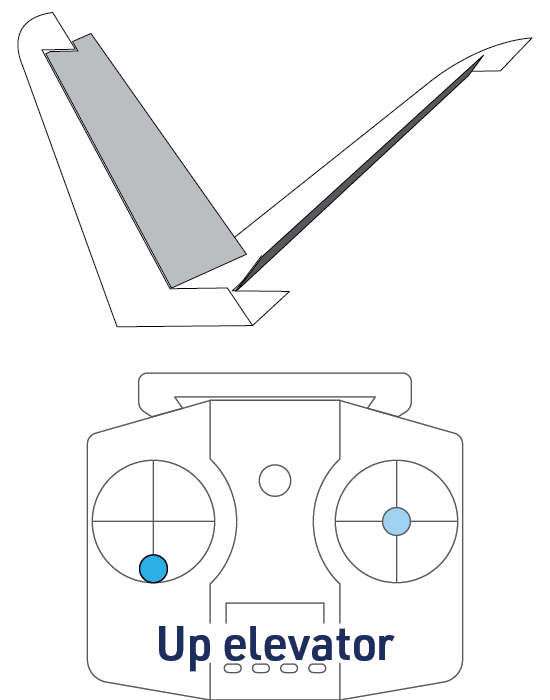
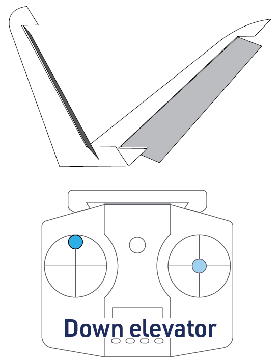
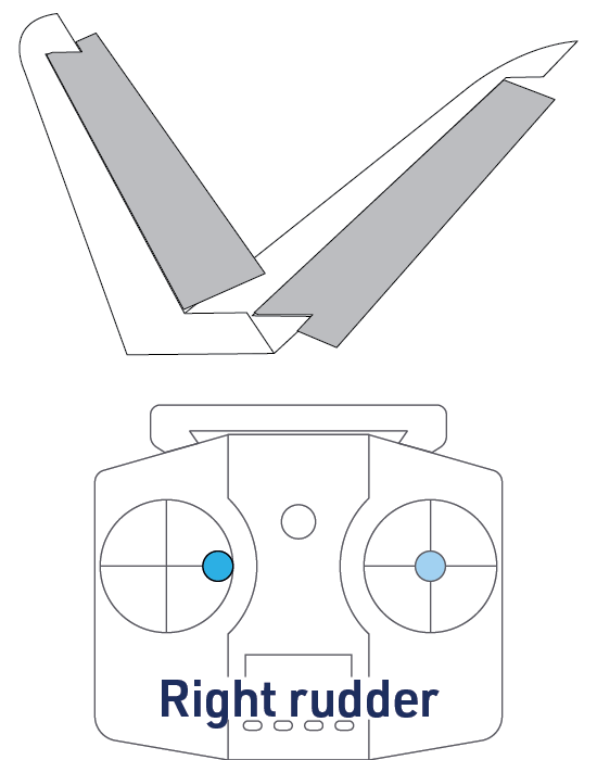
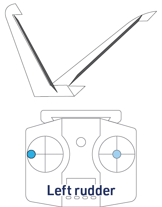
Trim the RC model in the same way, using the transmitter sticks to control the flight and the trims to adjust the neutral positions. Check the V-tail mix on the ground: up elevator moves both surfaces up, down elevator moves both down; right rudder moves the left surface up and right surface down, and left rudder does the reverse. All directions are viewed from behind. (Fig. 2) (Fig. 3) (Fig. 4) (Fig. 5)
Towline and bungee launching
Once the model is trimmed, you can tow it with a 50m fishing line or use a bungee comprising 5 m of 3×2mm rubber strip and 20 m of thin fishing line. Tie a metal key ring to the model end of the line, preferably with a bowline knot. Attach a red cloth flag 20–30 cm from that end to make the line visible in the air and on the ground. Store the line on a suitable spool to prevent tangles.
Appendix
Manufacturer's responsibility
As the kit manufacturer, we supply a high-quality kit and detailed instructions. The flight characteristics and performance of the finished model depend on how you build it. Since we cannot control how you complete and operate the model, we cannot assume responsibility for damage caused by or related to the operation of your completed model.