KAVAN Vinx 600mm - Instruction manual
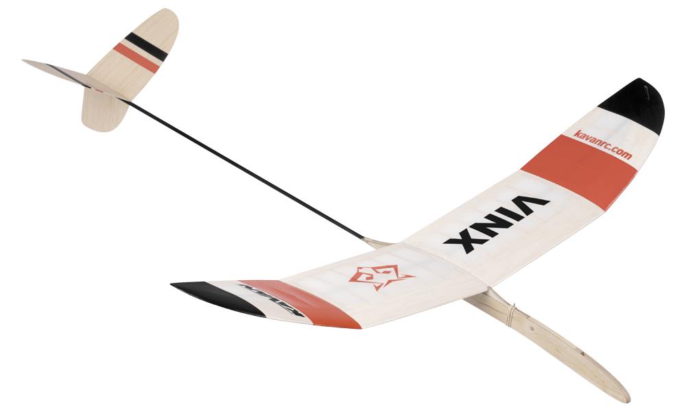
KAVAN Vinx – kit
Introduction
The contest free-flight discus launch glider (DLG) Vinx is intended for beginners with some experience of building simple models. This kit is a great introduction to the classic „balsa construction/dope & tissue“ model building and covering. With a little help from an experienced DLG flyer you can fine tune your Vinx turning it into a high performance contest model. You will need some basic modeller’s tools, glues and dopes – you will find these handy with any of your future projects as well. Please make yourself familiar with the building plans and this manual before you actually start the assembly.
Before you start
- If you are new to model aircraft, ask an experienced modeller to check your completed model and help you with the first flights. Your model shop or local model flying club can help you find an instructor.
- Build the model according to these instructions. Do not alter or modify it, as this can make it unsafe or unable to fly. Take time to build everything straight, true and strong.
- Check the kit for missing or damaged parts before starting. Familiarise yourself with each component and contact your dealer immediately if a replacement is needed.
- Trial fit every part before gluing. Check that you have the correct part and that it fits properly; extra glue cannot compensate for a poor fit.
- Set the centre of gravity (CG) and flight trim as described in Pre-flight preparation before the first flight. Incorrect balance can make the model unstable or unable to fly.
Check the contents and report missing or damaged parts before starting construction.
Safety precautions
This model is not a toy. Even though it is light and slow in flight, incorrect handling can cause injury or damage. Build, test and fly it responsibly, following the instructions, applicable model flying safety rules and common sense.
Use suitable tools and accessories in good condition. Install all parts correctly and check the model before the first and every subsequent flight. Do not fly a damaged model. Beginners should fly with help from an experienced modeller.
Children under the age of 14 must operate the model under adult supervision. Fly in calm weather or a light breeze at a safe site away from obstacles.
Features
- Classic all-balsa build
- High-performance contest glider
- Designed and manufactured in the Czech Republic
- Tilting wing suitable for a fuse, electronic or mechanical dethermaliser
- Easy to build
- Great flight characteristics
Technical specifications
| Parameter | Value |
|---|---|
| Wingspan | 600 mm |
| Length | 705 mm |
| Wing area | 7 dm² |
| All-up weight | 57 g |
Set contents
CNC-cut and pre-sanded fuselage, wing and tail parts, carbon tail boom and wing spars, small accessories and ballast, sticker sheet, full-size building plan and illustrated instruction manual.
Recommended glues
You can use solvent-based modeller's glue (UHU® Hart etc.), water-resistant white glue (KAV56.9960 / KAV56.9961, BISON® Super Wood etc.) or CA (KAV56.9951 Power CA Thin, KAV56.9952 Power CA Medium, KAV56.9953 Power CA Thick) with an accelerator (KAV56.9983 KAVAN PRO Accelerator CA Spray), and 5min epoxy (KAV56.9962 KAVAN Epoxy 5min).
Covering material
Oralight® iron-on film or 13–17 g/m² covering tissue (KAV524.13 Japan paper white 13 g/m²)
Recommended dopes
For tissue covering, use KAVAN Standard adhesive dope (KAV56.9988), shrinking dope (KAV56.9986), protective dope (KAV56.9989) and matching thinner (KAV56.9992 / KAV56.9992A). KAVAN Color coloured shrinking dopes (KAV56.9987.x) may also be used. Follow the product labels when selecting compatible materials.
Tools and accessories
You will need a perfectly flat building board (at least 300×700 mm), modeller’s knife (KAV66.770) with no. 11 blades, razor saw, drill with a drill bit set including a 3.5mm bit, model hobby sealing iron (KAV66.8335), sanding blocks with No. 120, 180, 240 and 360–400 grit sandpaper, modeller’s pins (KAV66.0355), scissors, flat and round fine file, soft flat (1/4"–3/8") brush, thin clear plastic film to protect the building plan (a large PE bag cut in half will work), paper masking tape, clear sticky tape 10–12 mm.
Main section
Model assembly
Use glues, dopes and thinners in a well-ventilated area, away from flames, sparks and other ignition sources. Follow the product labels and avoid inhaling vapours or sanding dust.
Lay the building plan on the building board and put a sheet of a thin clear plastic film to protect the building plan. Before applying the glue, please always double check the correct size, shape and alignment of the particular part.
Fuselage
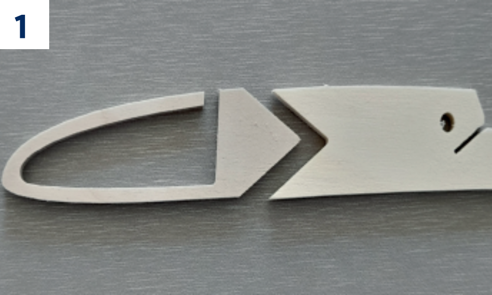
- Glue the T1 and T2 parts together using thick cyano or 5min epoxy. (Fig. 1)
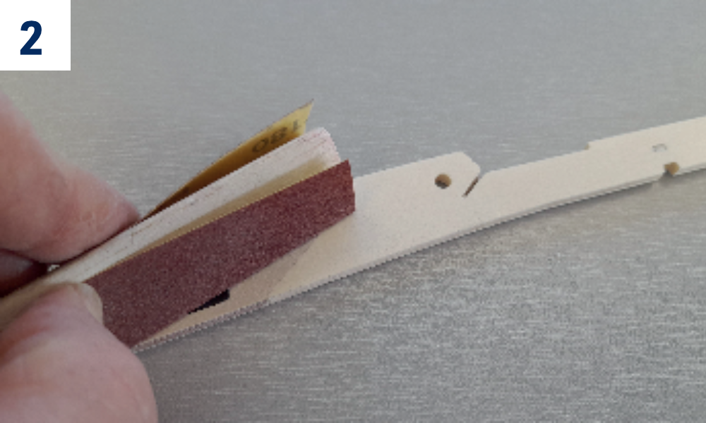
- Sand the joint flush once the glue has cured. (Fig. 2)
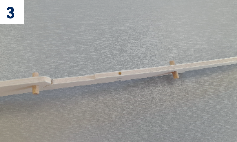
- Insert the T6 beech dowels into the fuselage. (Fig. 3)
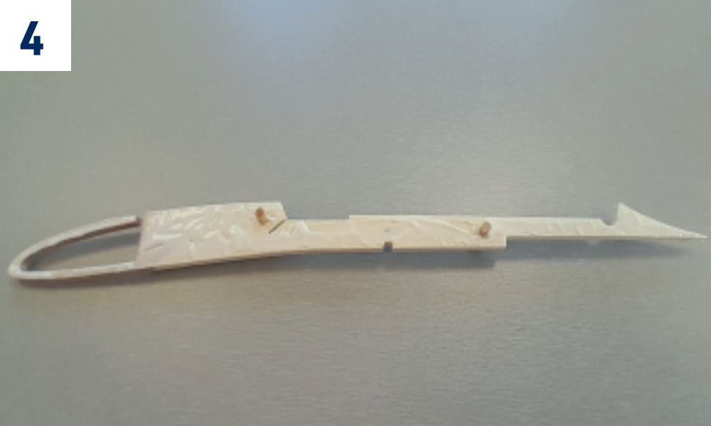
- Trial fit the T4 fuselage sides onto the T6 dowels. Trim the holes in the sides with a fine round file if necessary. (Fig. 4)
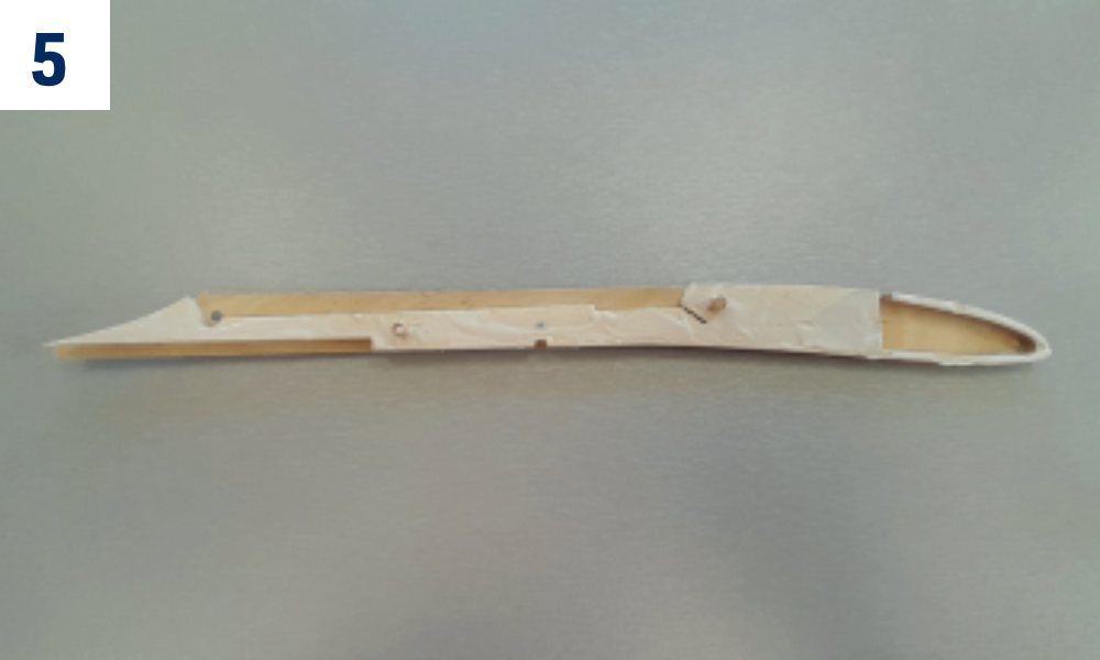
- Apply white glue onto the fuselage (except for the areas indicated (Fig. 5)) and press the fuselage sides in place.
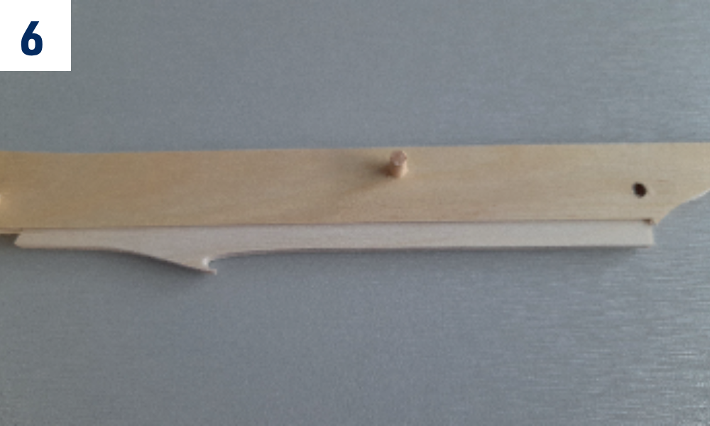
- Insert the T3 wing seat partially between the fuselage sides. (Fig. 6)
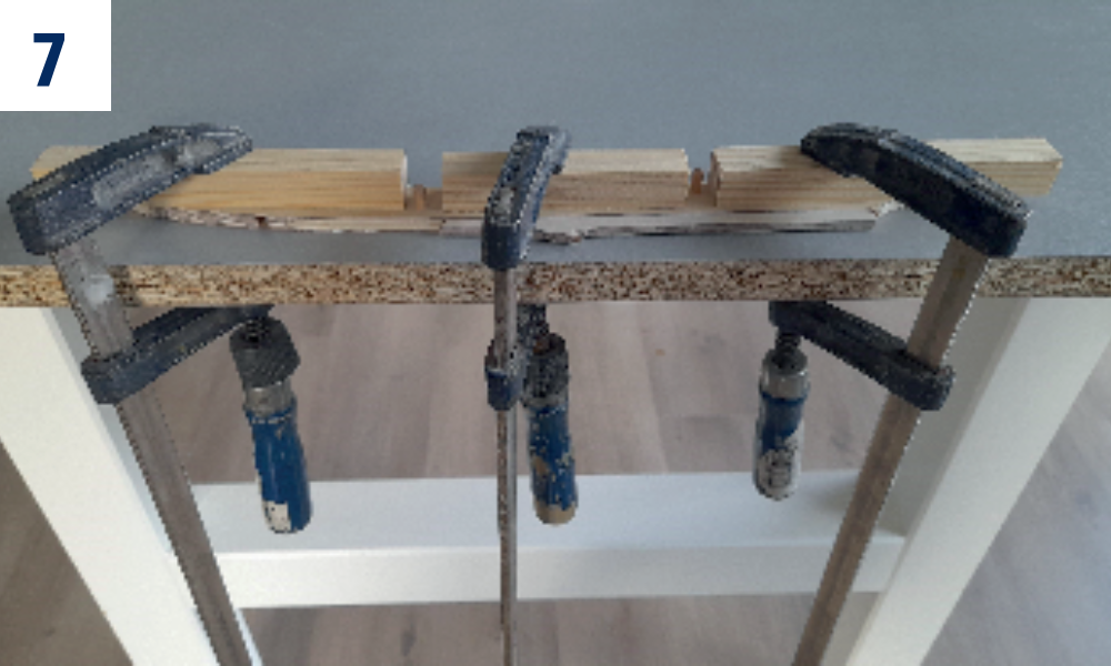
- Clamp the fuselage onto a flat support block (with help of small wooden blocks) to keep the fuselage straight and true until the glue cures. (Fig. 7)
Note
Put a thin clear plastic film between the fuselage and the support block in order to prevent sticking together.
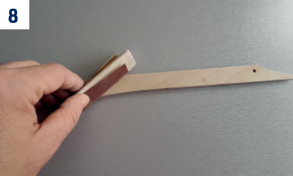
- Sand the T6 dowels flush with the fuselage sides. (Fig. 8)
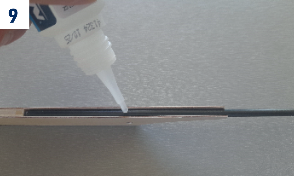
- Insert the carbon tube of the T5 tail boom into the fuselage; apply thin cyano to the joint and spray a little bit of CA accelerator onto it. Fill the corners between fuselage sides and the tail boom with thick cyano, apply CA accelerator onto it. (Fig. 9)
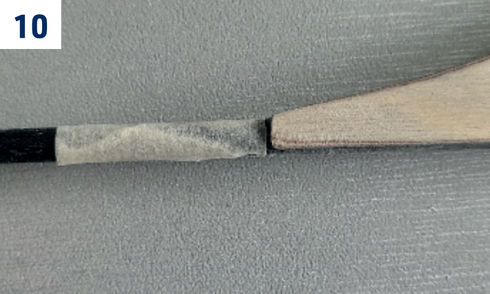
- Wrap the tail boom T5 with a paper masking tape next to the fuselage in order to protect it during sanding. (Fig. 10)
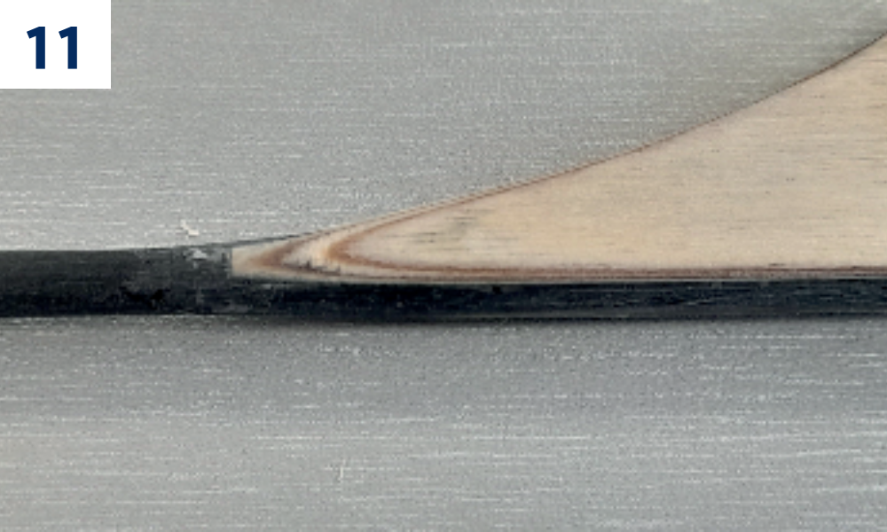
- Round the edges of the fuselage, carefully sand the wooden parts to create smooth transition to the tail boom. (Fig. 11)
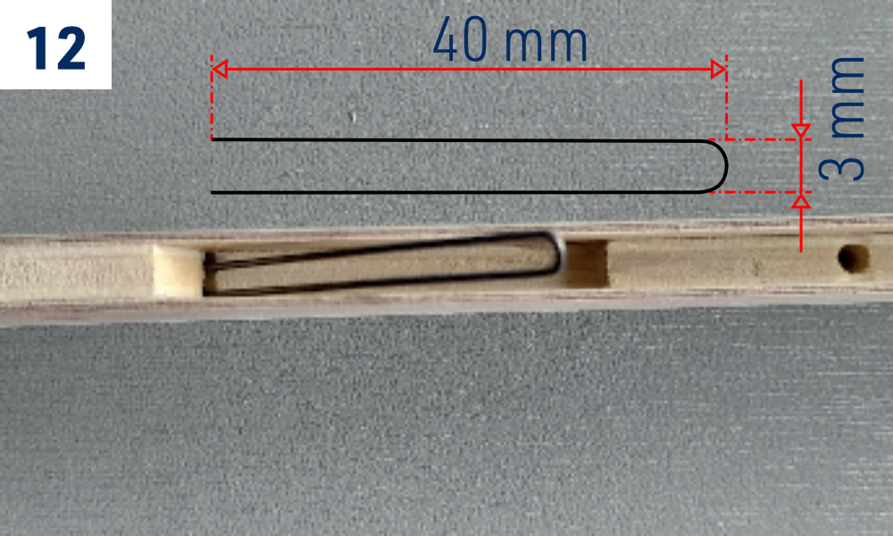
- Remove any remaining hardened glue in the slot between the fuselage sides. Bend the T10 wire into the 40×3 mm spring shape (Fig. 12) and glue it with medium cyano in place, apply CA accelerator onto it.
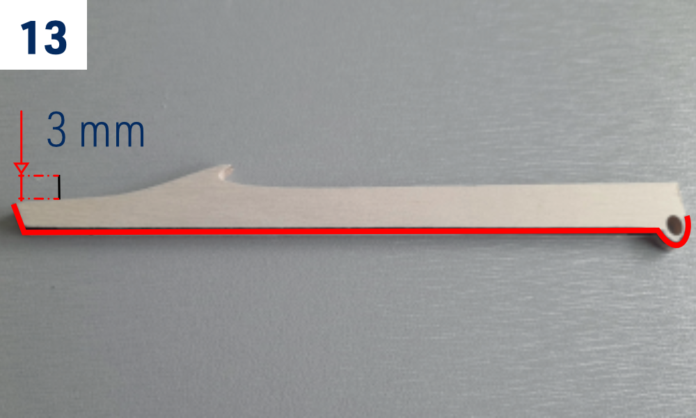
- Round the edges of the T3 wing seat as shown (Fig. 13); glue the T11 pin into T3 with the 6mm projection shown. Insert the T3 into the fuselage; it has to move easily within without any binding – trim if necessary. Apply three layers of protective dope (diluted 1:1) to the T3 wing seat (except for the hole for the T8 pin), sand with No. 360 sand paper after each layer (except for the last one).
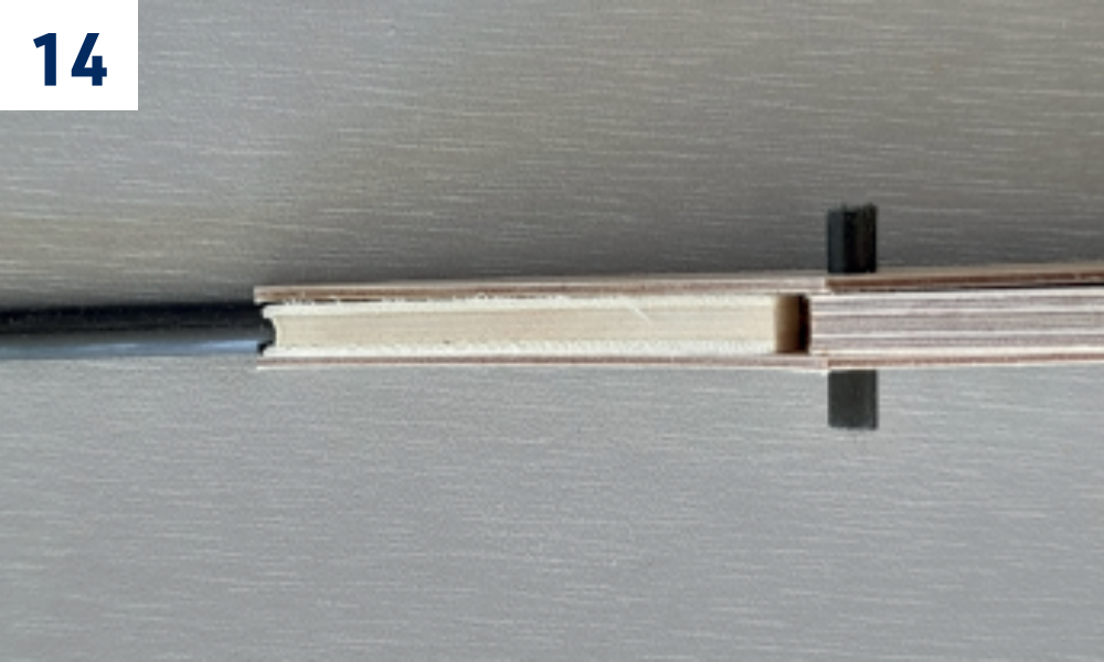
- Apply three layers of protective dope (diluted 1:1) to the fuselage, sand with No. 360 sand paper after each layer (except for the last one). Insert the T3 wing seat to the fuselage and secure it with the T8 pin – the T3 wing seat has to swing on the pin without any binding. (Fig. 14)
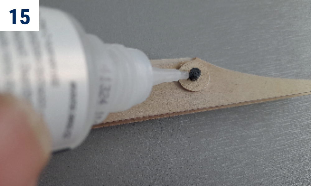
- Once satisfied, slide the T7 and T9 rings onto the T8 pin and glue the rings with thick cyano to the fuselage. (Fig. 15)
Be sure the T3 wing seat could move easily; prevent glue from reaching the T3 and T8 pin.
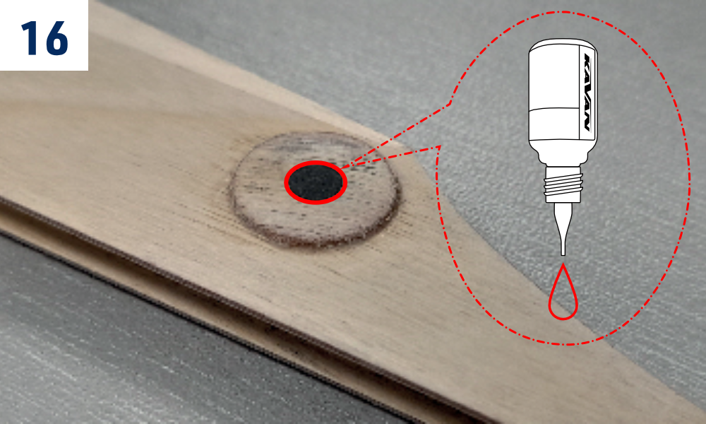
- Sand the T8 pin flush with the T7/T9 rings. Apply small amount of medium cyano to the T8 pin to glue it to the rings (but not to the T3 wing seat). Apply three layers of protective dope (diluted 1:1) to the rings. (Fig. 16)
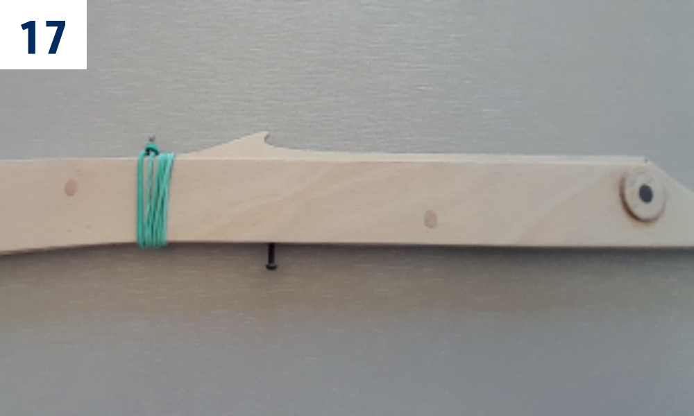
- Screw the T12 M2 setting screw into the fuselage; secure the T3 wing seat with a rubber band. (Fig. 17)
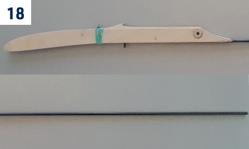
- The fuselage is ready for final assembly. (Fig. 18)
Tail feathers
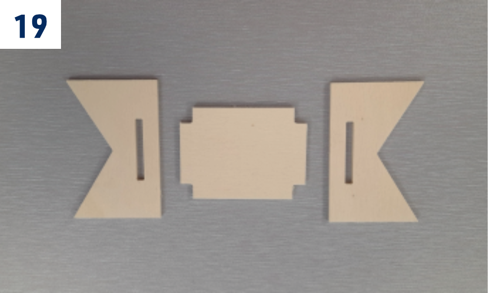
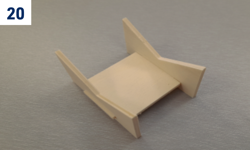
- Locate the P2 and P3 parts of the tailplane jig. (Fig. 19)
- Glue the jig together using white glue. (Fig. 20)
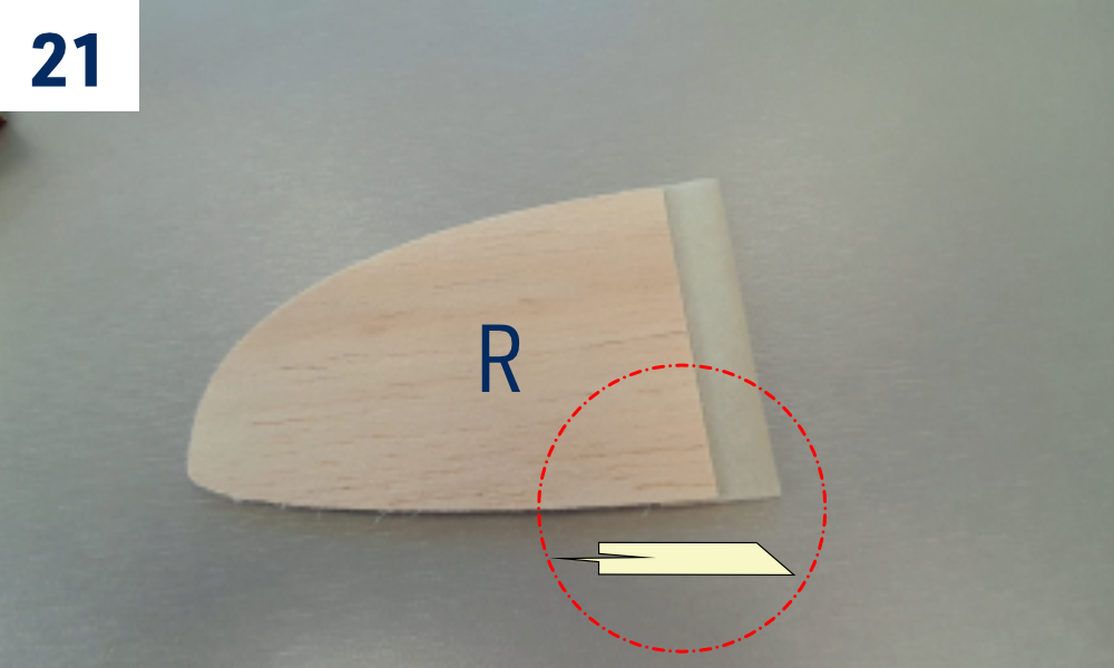
- Apply a strip of paper masking tape to the bottom side of the right half of the horizontal tailplane. (Fig. 21)
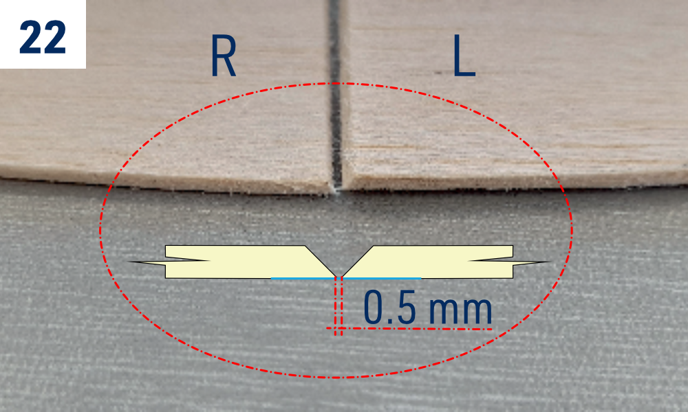
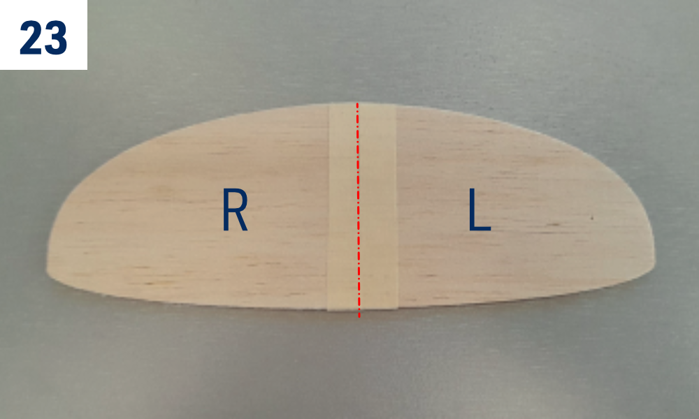
- Stick the left half of the horizontal tailplane to the tape, leaving the 0.5mm gap shown between the halves. (Fig. 22)+(Fig. 23)
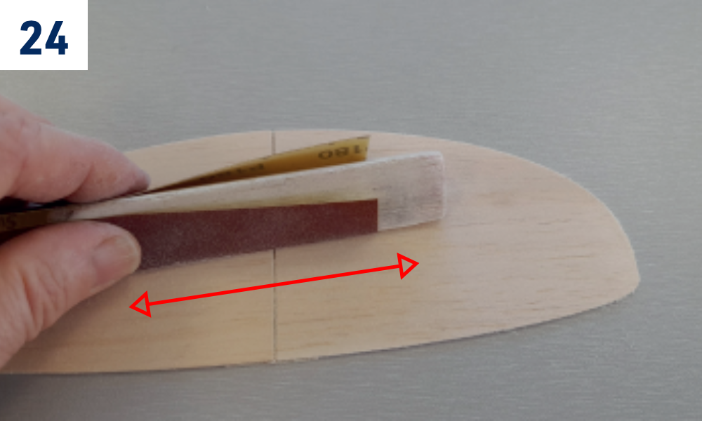
- Sand the entire horizontal tailplane with No. 240 sand paper; round the outer edges. (Fig. 24)
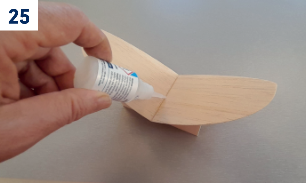
- Put the horizontal tailplane on the tailplane jig (the side with the masking tape down), press it to the jig and glue the halves together with thin cyano. Once the glue sets remove the tape and carefully sand the joint smooth. Apply two layers of protective dope (diluted 1:1), sand with No. 360 sand paper after each layer (except for the last one). (Fig. 25)
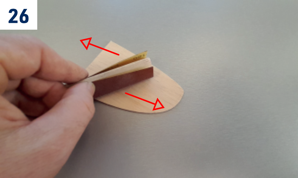
- Sand the entire vertical tailplane O1 with No. 240 sand paper; round the outer edges. Apply two layers of protective dope (diluted 1:1), sand with No. 360 sand paper after each layer (except for the last one). (Fig. 26)
Wing
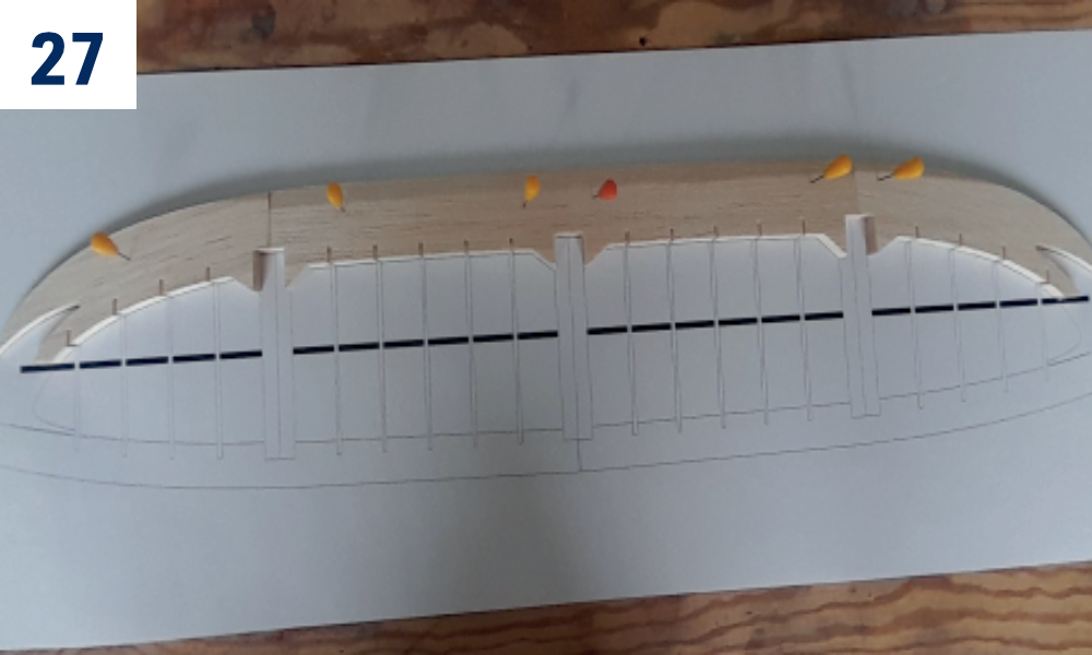
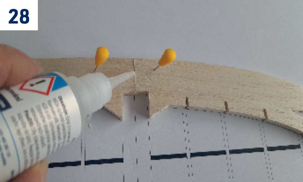
- Lay the building plan on the building board and put a sheet of a thin clear plastic film to protect the building plan. Pin down the leading edge parts K1 to the building plan; tack glue them together with a few small drops of thin cyano. (Fig. 27)+(Fig. 28)
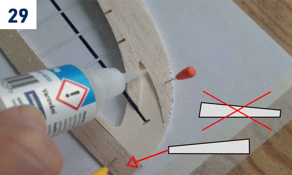
- Insert the K3 wing tips into the leading edge, press it down to the building board and glue in place with thin cyano; use CA accelerator if needed. Pin down the K2 trailing edge to the building plan and glue it to wingtips with thin cyano. (Fig. 29)
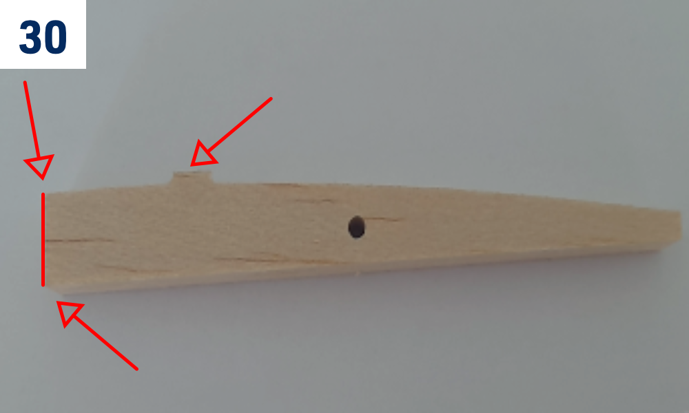
- Use a sharp modeller’s knife to carefully cut the ribs off the K6 8 mm balsa sheet. Sand off the „bridge“, round the front edge. (Fig. 30) Do not break the ribs out.
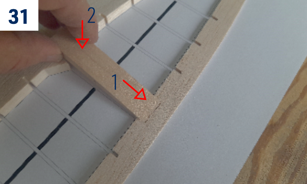
- Insert the 8 mm ribs K6 into slots in the leading and trailing edges – into the trailing edge first, then to the leading edge. (Fig. 31)
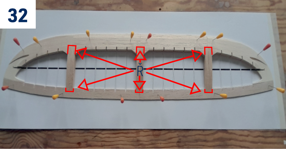
- Glue the ribs in place with thin cyano. (Fig. 32)
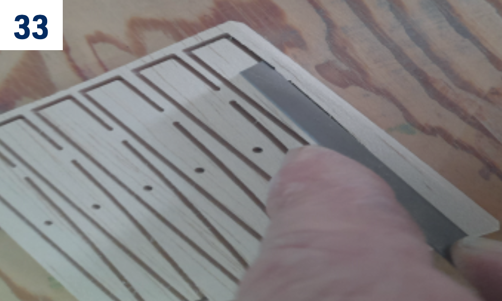
- Use a sharp modeller’s knife to carefully cut the wing outer panel ribs off the K8 2 mm balsa sheet. Sand off the „bridge“, round the front edge (Fig. 30). (Fig. 33) Do not break the ribs out.
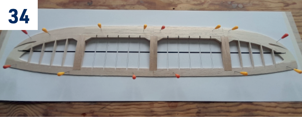
- Insert the ribs into slots in the leading and trailing edges – into the trailing edge first, then to the leading edge. (Fig. 34)
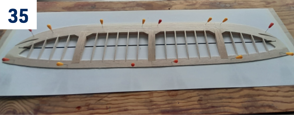
- Use a sharp modeller’s knife to carefully cut the wing centre section ribs off the K7 2 mm balsa sheet. Sand off the „bridge“, round the front edge (Fig. 30). Insert the ribs into slots in the leading and trailing edges – into the trailing edge first, then to the leading edge. (Fig. 35) Do not break the ribs out.
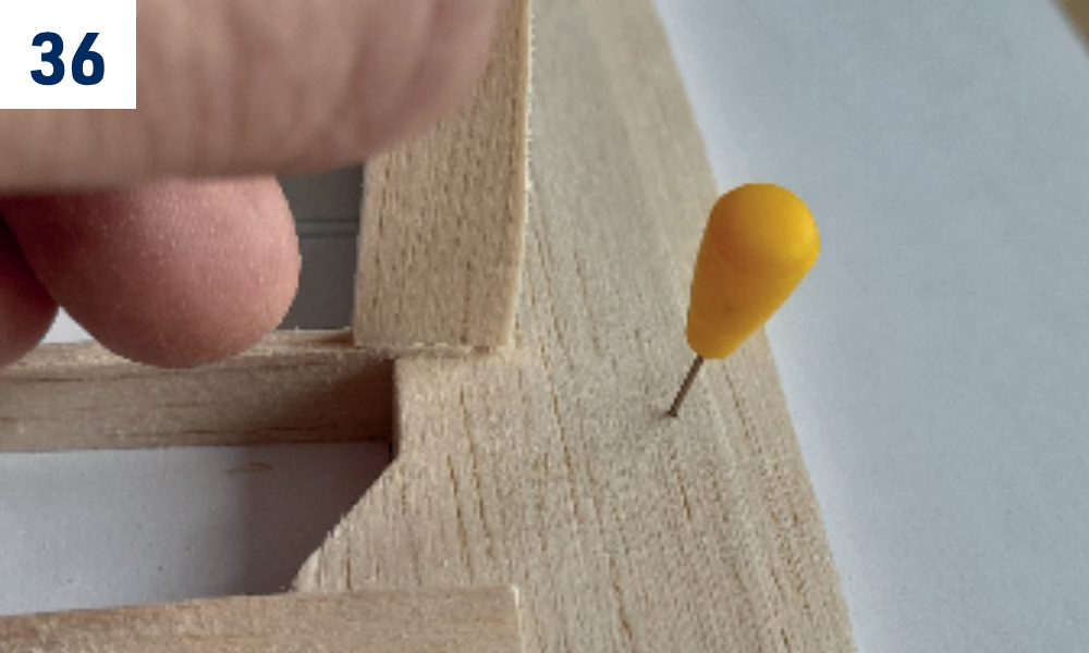
- Double check the correct alignment of all ribs – trim to get a perfect fit if necessary. Glue the ribs in place with thin cyano. (Fig. 36)
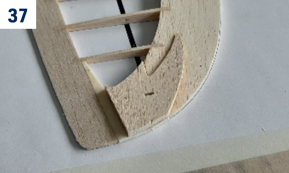
- Glue the K4 reinforcement plates onto the K3 wing tips using thick cyano. (Fig. 37)
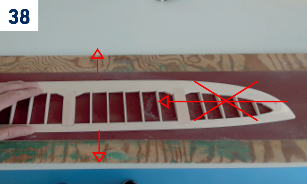
- Sand the bottom side of the wing smooth. Sand only in the direction indicated as shown (Fig. 38); don’t push down too much to prevent damage to the ribs. The sanding will be quite easy if you glue No. 120 sandpaper to a wooden board approximately 150×600 mm as shown (Fig. 38).
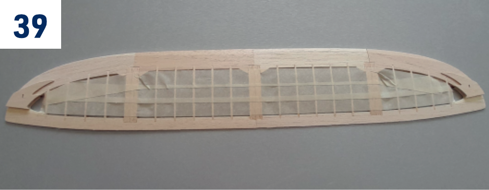
- Cover the top side of the ribs with strips of paper masking tape in order to protect the ribs. (Fig. 39)
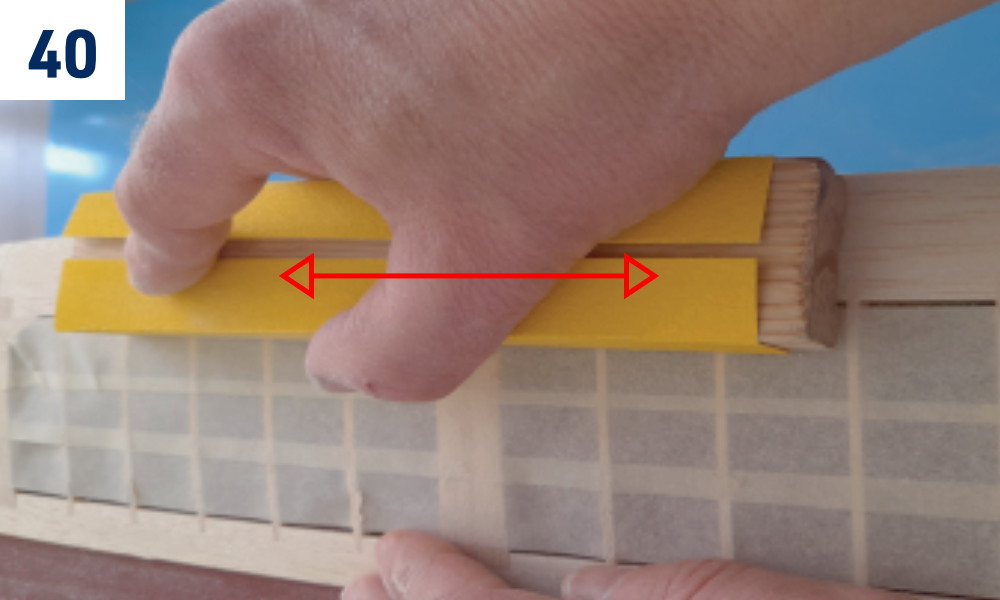
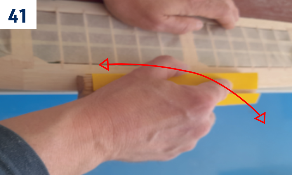
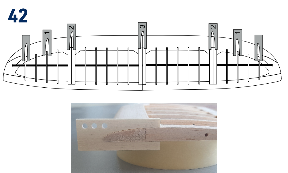
- Sand the leading edge to the correct shape using the K10 to K13 templates (template marking – (Fig. 42)). Use No. 120 sand paper, sand lightly, do not push too much. (Fig. 40)+(Fig. 41)
- Checking the correct shape of the leading edge. (Fig. 42)
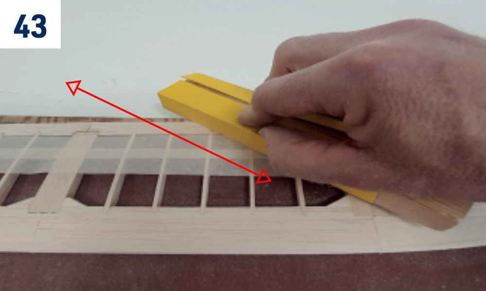
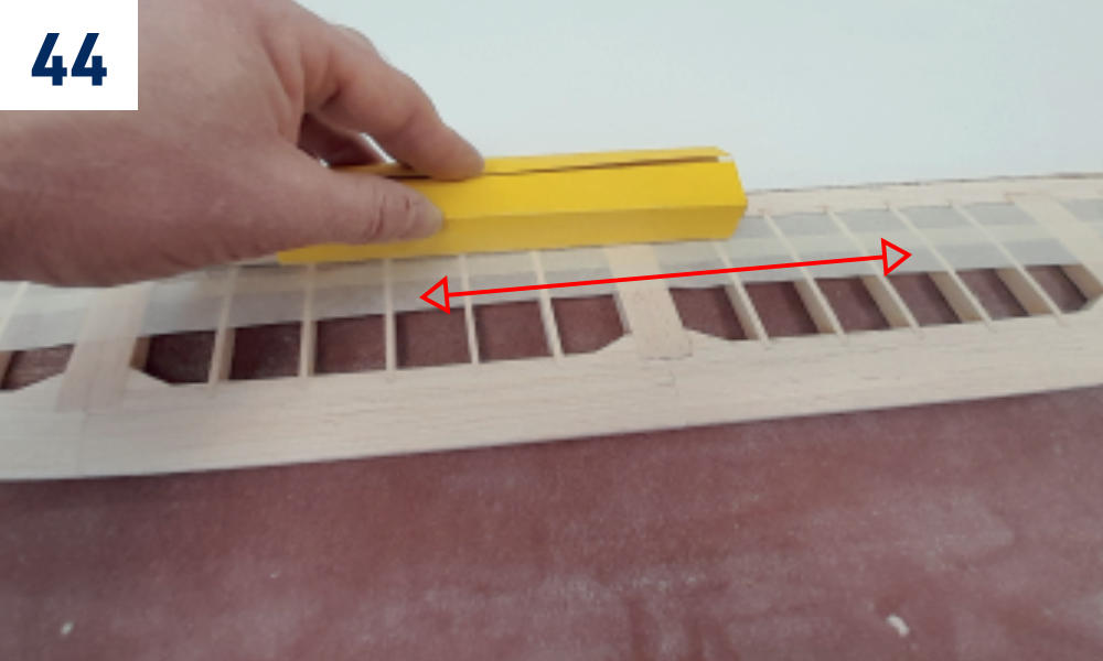
- Sand the trailing edge using No. 120 sand paper. Sand lightly in the indicated directions; do not push down too much. (Fig. 43)+(Fig. 44)
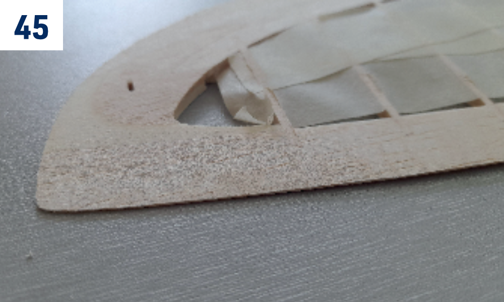
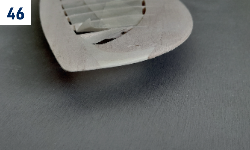
- Sand to shape the wing tips as well. Remove the masking tape and sand lightly the entire wing (including ribs) using No. 240 sand paper. (Fig. 45)+(Fig. 46)
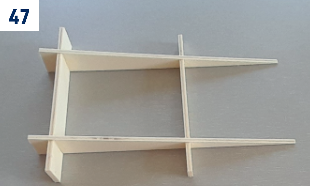
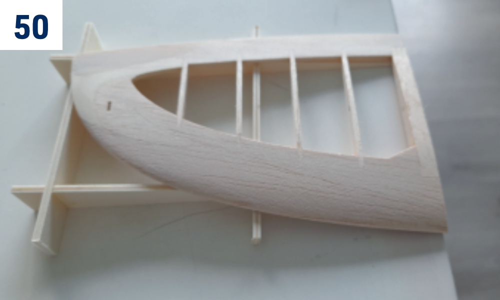
- Glue together the bevel guide jig consisting of parts P11, P12 and P13 using thick cyano. (Fig. 47)
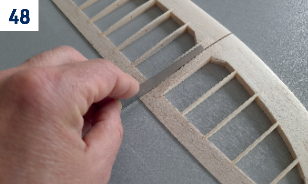
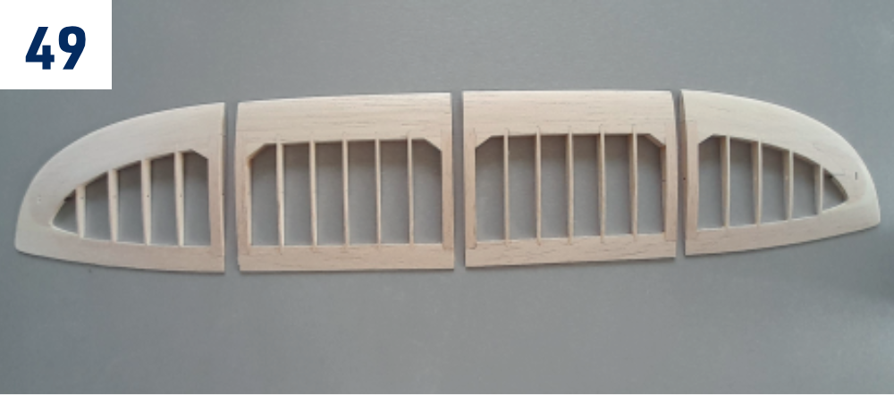
- Carefully separate the wing panels using a razor saw. (Fig. 48)+(Fig. 49)
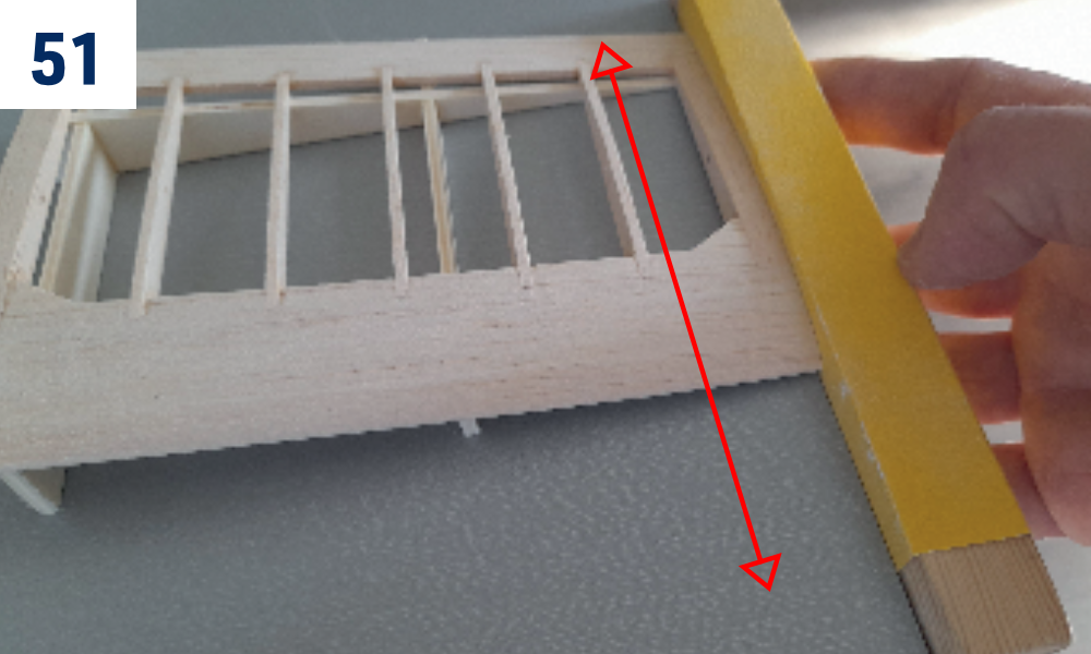
- Align the bevel guide jig with the edge of your building board and bevel the root and outer ribs of all wing panels. (Fig. 50)+(Fig. 51)
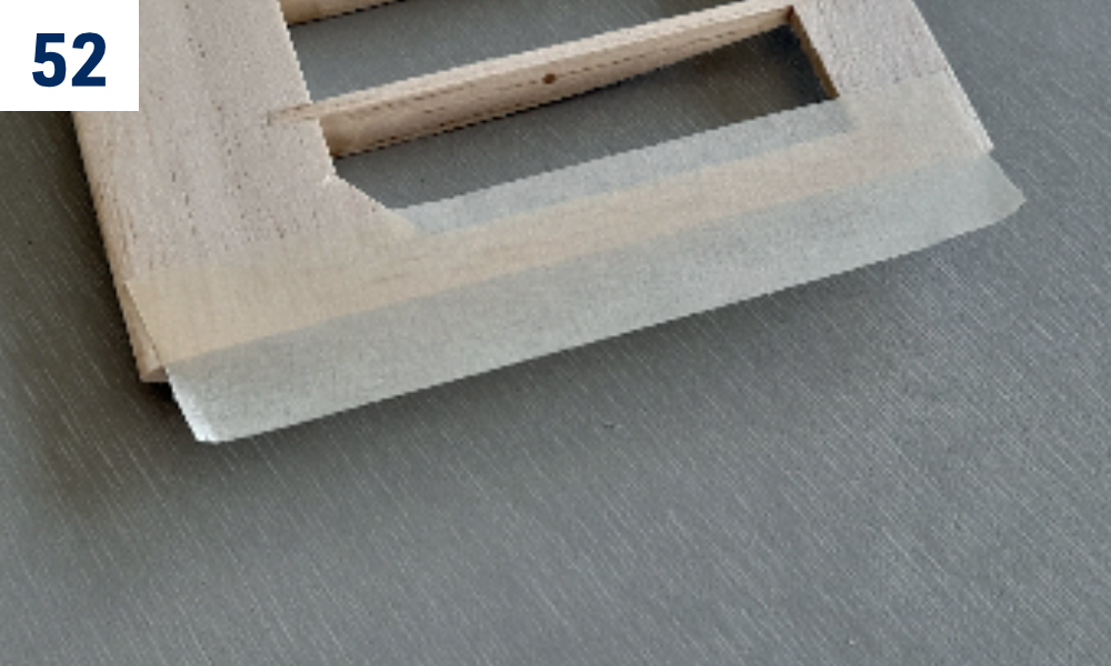
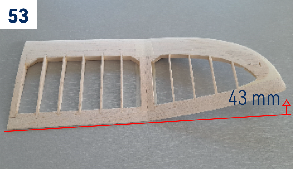
- Join the left and right halves of the wing centre section together with the corresponding outer panels with a strip of masking tape and check the 43mm dihedral as shown (Fig. 53). (Fig. 52)
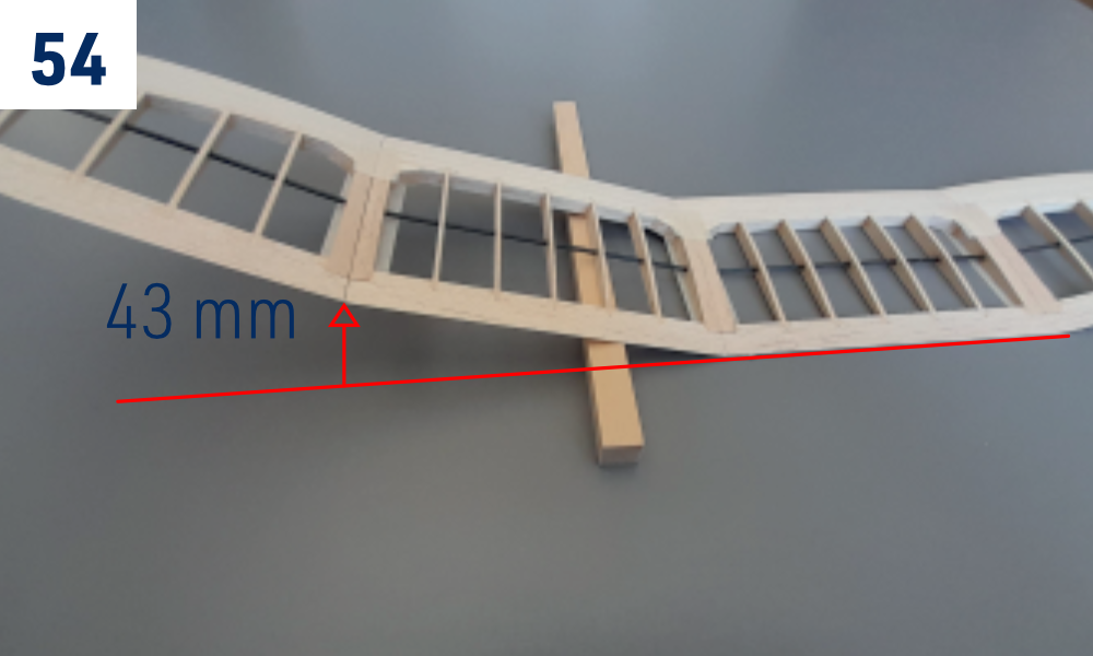
- Join the wing halves with a strip of masking tape and check the 43mm dihedral at the position indicated as shown (Fig. 54).
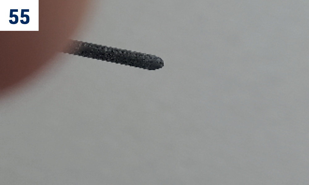
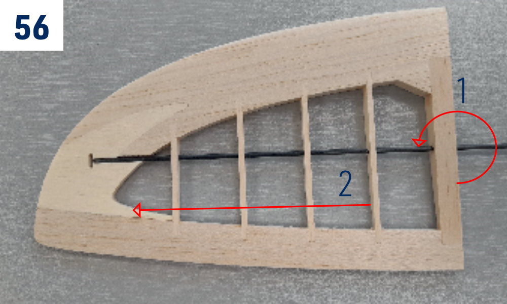
- Round the edge of the K5 Ø2 mm carbon tube. (Fig. 55)
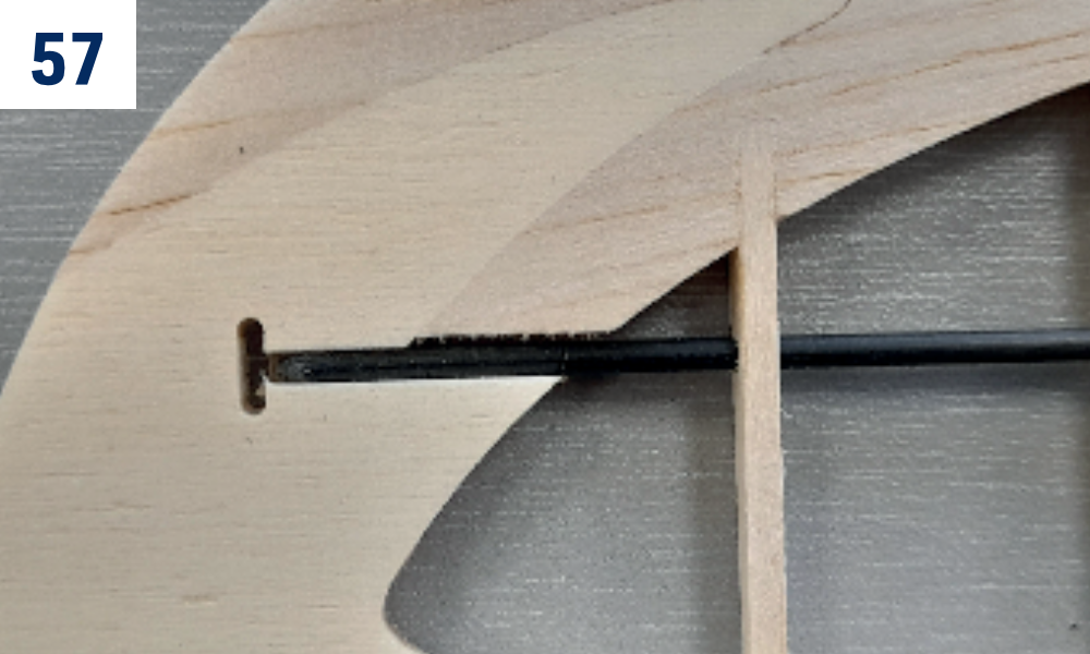
- Thread the tube through the ribs of the right wing outer panel and into the wing tip (Fig. 57). (Fig. 56)
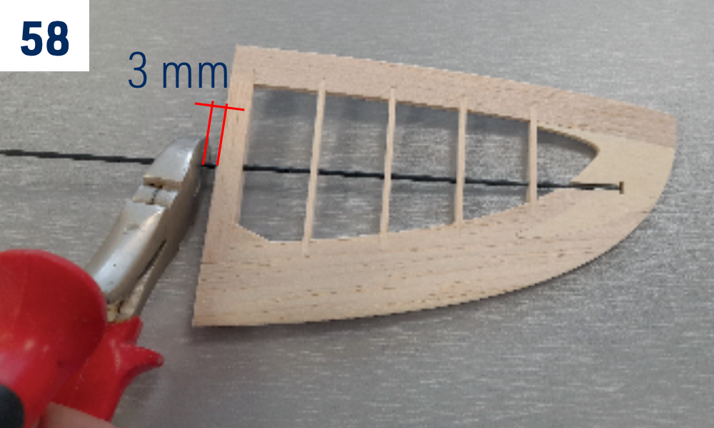
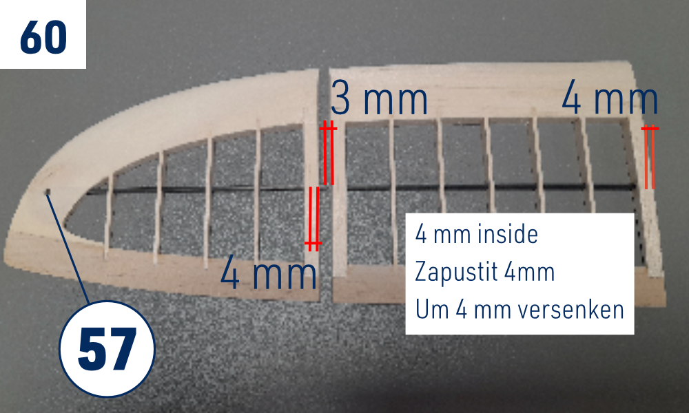
- Cut the tube so it sticks out by 3 mm out of the root rib. (Fig. 58)
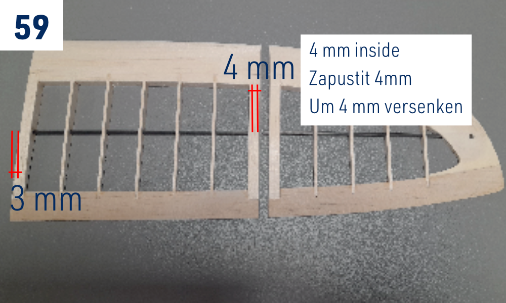
- Thread the tube through the ribs of the right wing centre section so it sticks out by 3 mm out of the root rib and is sunk by 4 mm in the outer rib. (Fig. 59)
- Thread the tube through the ribs of the left wing centre section so it sticks out by 3 mm out of the outer rib and is sunk by 4 mm in the root rib. Thread the tube through the ribs of the left wing outer panel and into the wing tip (Fig. 57) whilst sunk by 4 mm in the root rib. (Fig. 60)
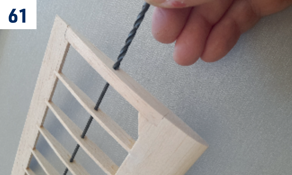
- Enlarge the rib holes at the recessed tube ends with a Ø3.5 mm drill bit. (Fig. 61)
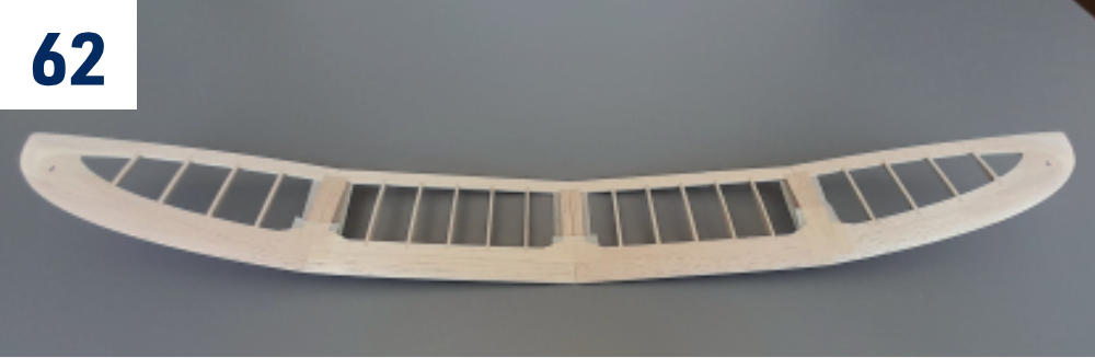
- Put together the entire wing using strips of masking tape as described above, double check the correct dihedral. Once satisfied, separate the wing panels again and glue the carbon tube main spar to the ribs and wing tips with thin cyano. (Fig. 62)
For Oralight® film covering, cover the separate wing panels as described in Iron-on film covering, then join them. Follow the film manufacturer’s temperatures.
For tissue covering, join the wing panels first as described in Joining the wing panels, then follow Dope & tissue covering.
Iron-on film covering
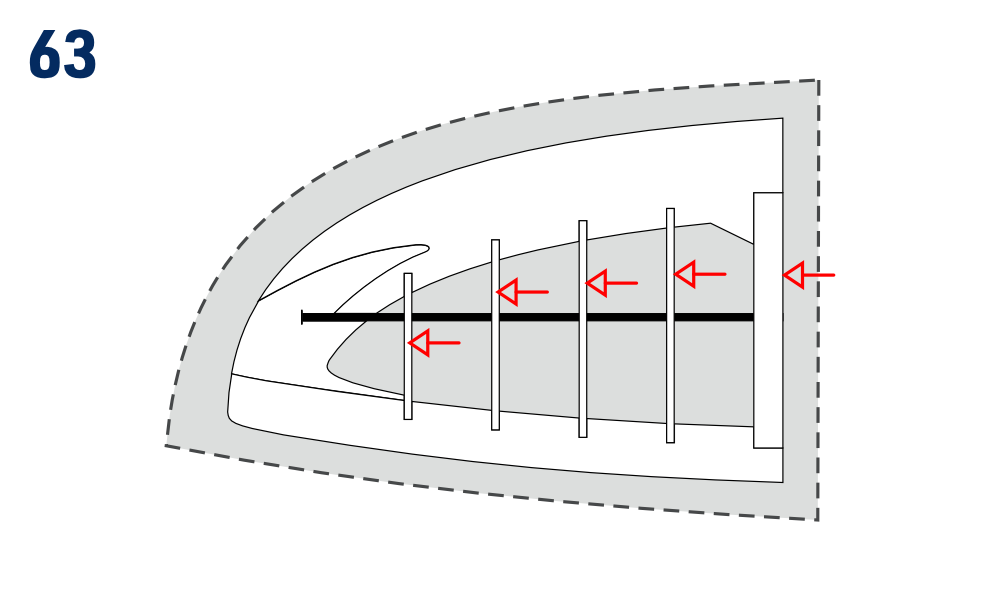
- Cut a piece of the iron-on film overlapping the outline of the wing panel by ca 1 cm. Punch two holes through each rib with a modelling pin in places indicated by arrows. (When ironing, the air trapped between ribs heats up and expands – the holes are here to vent it safely.) (Fig. 63)
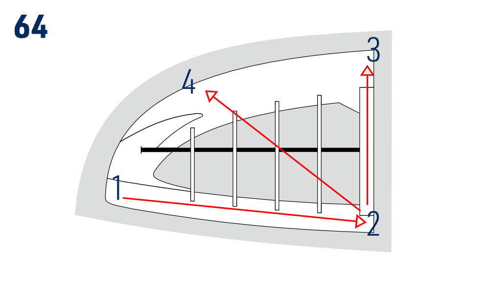
- Set the temperature of your sealing iron for sticking the film as recommended by the manufacturer of the iron-on film. Lay the film down on the bottom side of the wing panel and tack the film to the wing panel with the tip of your sealing iron in spots and sequence indicated by arrows and numbers. (Fig. 64)
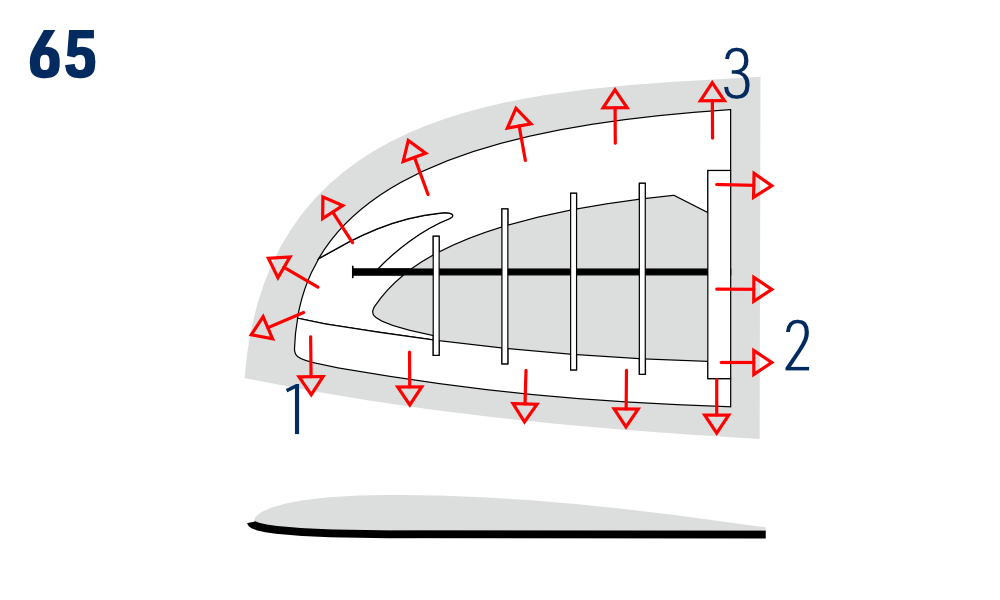
- Iron-on the film all around the outline as indicated by arrows and numbers. Cut the film around the edges and seal with your sealing iron. (Fig. 65)
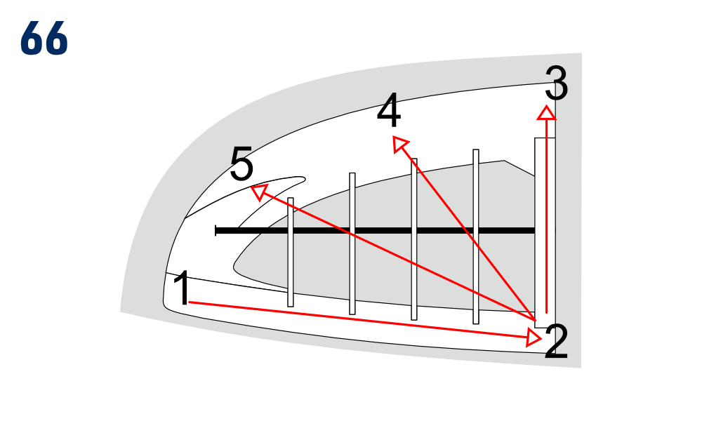
- Lay the film down on the top side of the wing panel; it should overlap the trailing edge by ca 4 mm. Tack the film to the wing panel with the tip of your sealing iron in spots and sequence indicated by arrows and numbers. (Fig. 66)
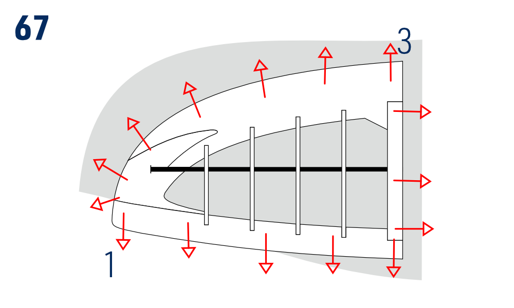
- Iron-on the film all around the outline as indicated by arrows and numbers. (Fig. 67)
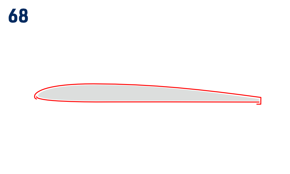
- Cut the film around the edges (except for the trailing edge) and seal with your sealing iron. Iron-on the film to the trailing edge overlapping to the bottom side. (Fig. 68)
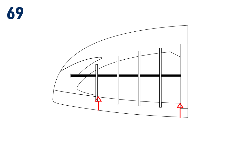
- Punch the covering film on the bottom side with a modelling pin (see the arrows). Increase the temperature of your sealing iron for shrinking the film as recommended by the manufacturer of the iron-on film. Shrink the top and bottom covering film. (Fig. 69)
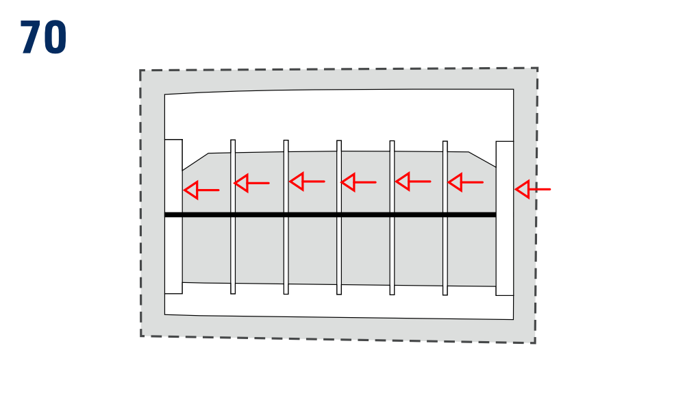
- Cut a piece of the iron-on film overlapping the outline of the wing centre section by ca 1 cm. Punch two holes through each rib with a modelling pin in places indicated by arrows. (Fig. 70)
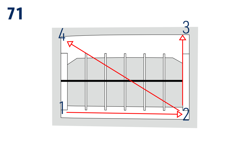
- Lay the film down on the bottom side of the wing centre section and tack the film to the wing with the tip of your sealing iron. (Fig. 71)
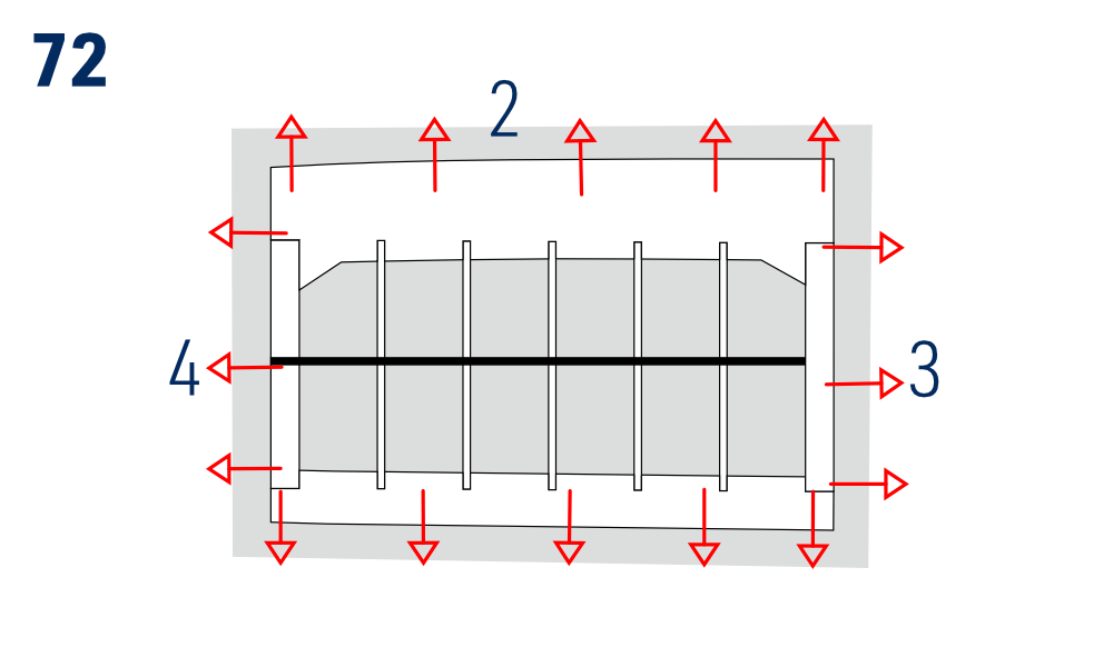
- Iron-on the film all around the outline as indicated by arrows and numbers. Cut the film around the edges and seal with your sealing iron. (Fig. 72)
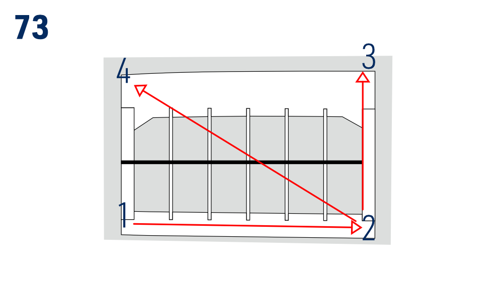
- Lay the film down on the top side of the wing centre section; it should overlap the trailing edge by ca 4 mm. Tack the film to the wing with the tip of your sealing iron. (Fig. 73)
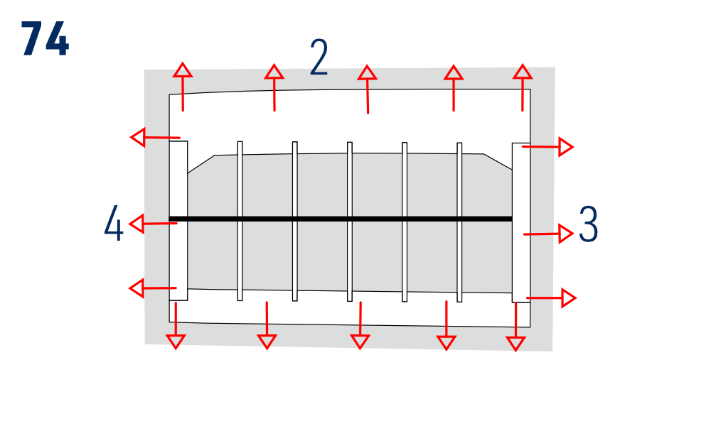
- Iron-on the film all around the outline as indicated by arrows and numbers. (Fig. 74)
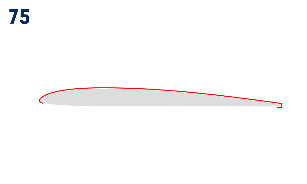
- Cut the film around the edges (except for the trailing edge) and seal with your sealing iron. Iron-on the film to the trailing edge overlapping to the bottom side. (Fig. 75)
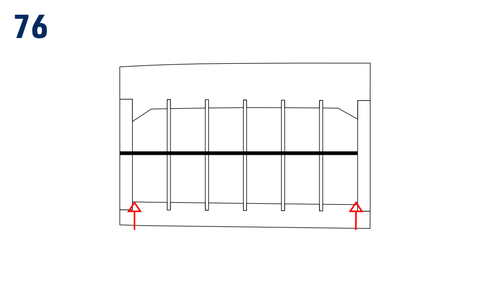
- Punch the covering film on the bottom side with a modelling pin (see the arrows). Increase the temperature of your sealing iron for shrinking the film as recommended by the manufacturer of the iron-on film. Shrink the top and bottom covering film. (Fig. 76)
Joining the wing panels
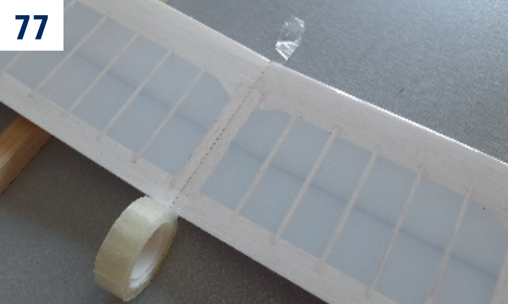
- As in the trial assembly, join the wing centre sections and wing panels – now using a clear sticky tape. Apply 5min epoxy to the ribs and glue together; double check the correct dihedral (Fig. 53) before the glue sets. Remove any excess glue with a paper towel soaked with rubbing alcohol immediately. (Fig. 77)
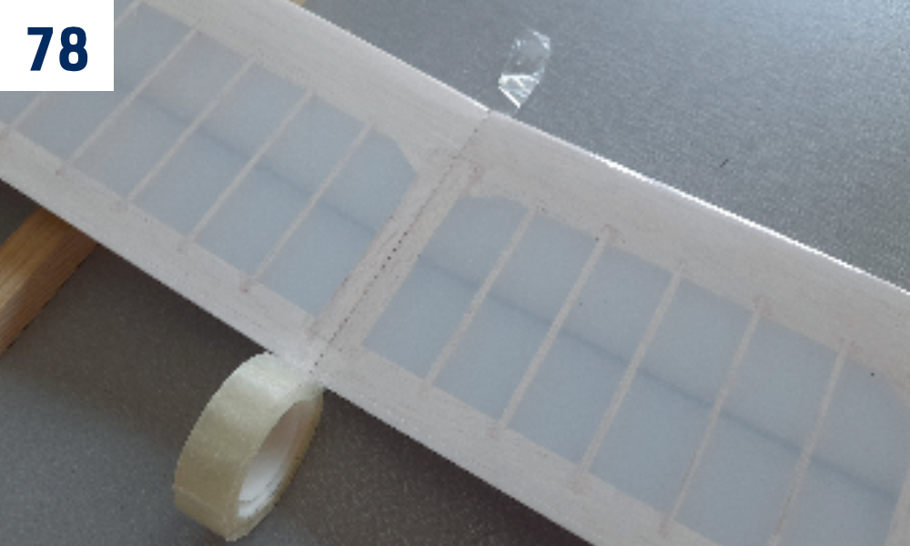
- As in the trial assembly, join the wing halves using a clear sticky tape. Apply 5min epoxy to the ribs and glue together; double check the correct dihedral (Fig. 54) before the glue sets. Remove any excess glue with a paper towel soaked with rubbing alcohol immediately. (Fig. 78)
Sealing film-covered joints
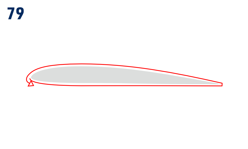
- Seal the joints with 10 mm wide strips of iron-on film or clear sticky tape. Start at the bottom of the leading edge, following to the trailing edge and then back to the leading edge, overlapping a little bit. (Fig. 79)
Wing twist
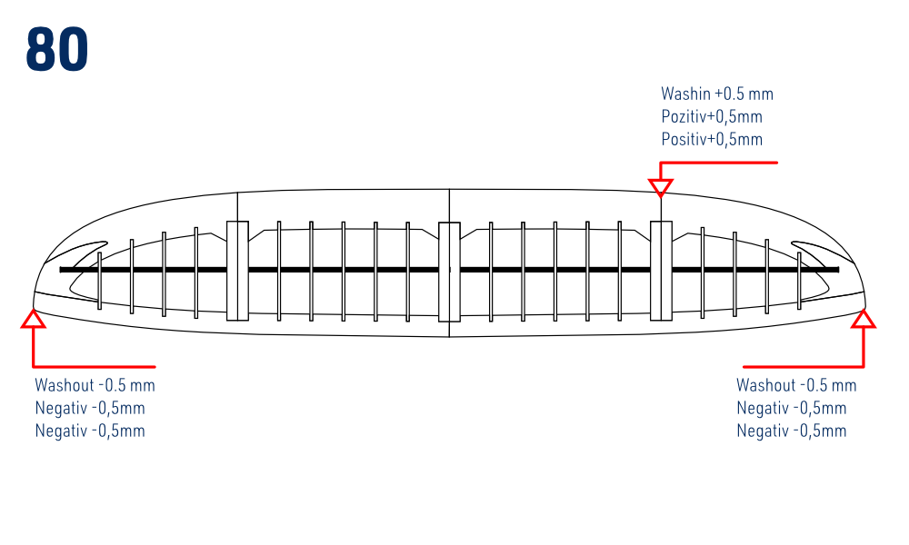
- Now it is the time to create the indicated washout and washin – these are critically important to increasing stability and achieving smooth gliding. Lay the wing down on a flat work bench, check the wing twist. The described washouts/washin is for right handed pilots and right turn glide; left handed pilots should go for mirror image setting. (Fig. 80)
Iron-on film covered wing: Use your sealing iron to heat up both the bottom and top covering film of the particular part of the wing, twist it a little bit more than required with your fingers and hold it that way until it cools down.
Tissue covered wing: Use a heat gun or a pot of hot water as a source of hot steam to twist the wing as required.
Left wing panel: −0.5 mm washout (The trailing edge is higher by 0.5 mm at the wing tip than at the root.)
Right wing panel: −0.5 mm washout
Right wing centre section: +0.5 mm washin (The leading edge is 0.5 mm lower at the outer end than at the root.)
Dope & tissue covering
First join the wing panels as described in Joining the wing panels.
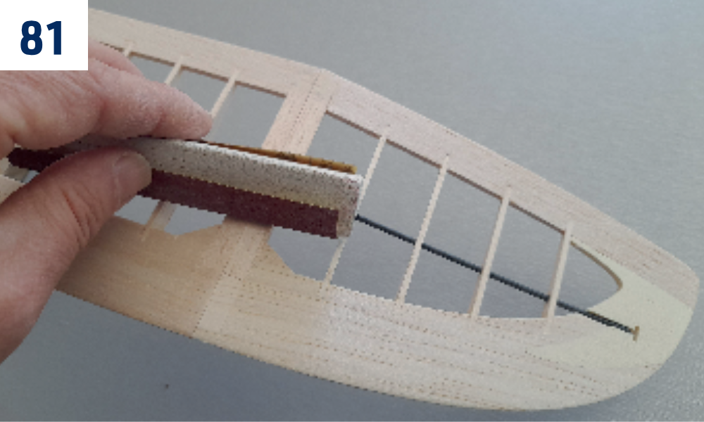
- Sand the glue joints with No. 240 sand paper. (Fig. 81)
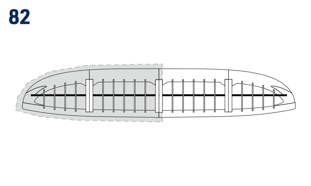
- Apply two layers of thin protective dope (diluted 1:1), sand with No. 360 sand paper after each layer (except for the last one). Cut two pieces of the tissue overlapping the outline of the left and right wing halves by ca 1 cm. (Fig. 82)
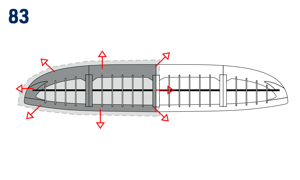
- Apply a coat of adhesive dope to the bottom of the right wing half using a soft flat brush; put the tissue on and press it lightly to the ribs and leading and trailing edges with your fingers, smoothing it. If the tissue does not stick enough to the wing frame, brush adhesive dope through the tissue. (Fig. 83)
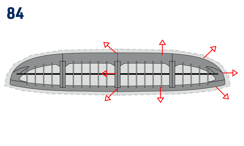
- Apply a coat of adhesive dope to the bottom of the left wing half; put the tissue on and press it lightly to the wing with your fingers, smoothing it. If the tissue does not stick enough to the wing frame, brush adhesive dope through the tissue. Once the dope sets, cut the tissue along the edges and brush adhesive dope to smooth it and stick to the wing. (Fig. 84)
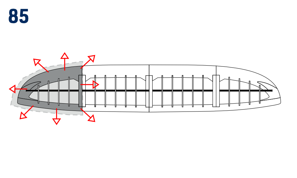
- Apply a coat of adhesive dope to the top of the left wing outer panel; put the tissue on and press it lightly to the wing with your fingers, smoothing it. If the tissue does not stick enough to the wing frame, brush adhesive dope through the tissue. Once the dope sets, cut the tissue along the edges and brush adhesive dope to smooth it and stick to the wing. (Fig. 85)
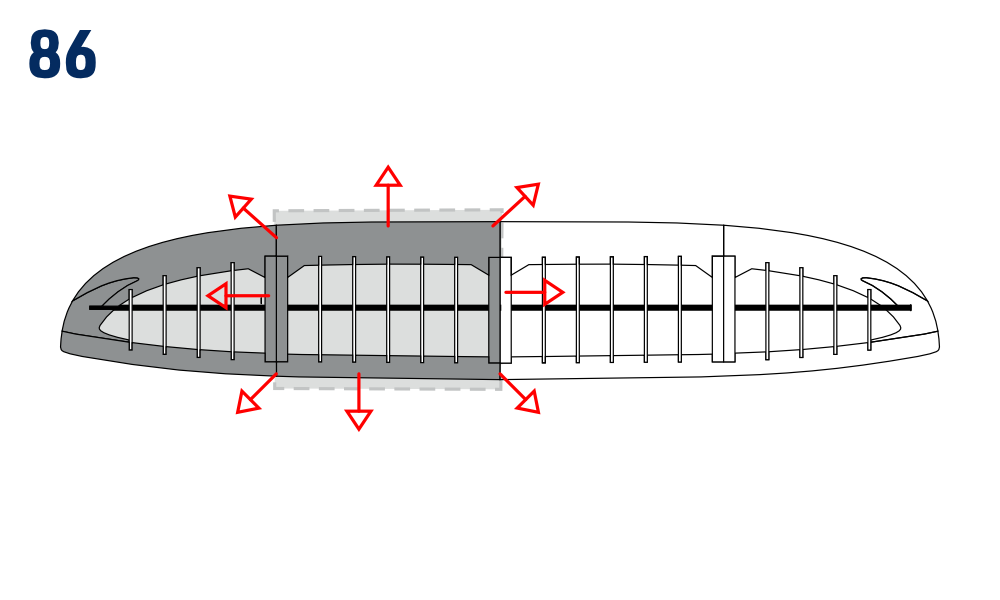
- Apply a coat of adhesive dope to the top of the left wing centre section; put the tissue on and press it lightly to the wing with your fingers, smoothing it. If the tissue does not stick enough to the wing frame, brush adhesive dope through the tissue. Once the dope sets, cut the tissue along the edges and brush adhesive dope to smooth it and stick to the wing. Cover the right wing half in the same manner. (Fig. 86)
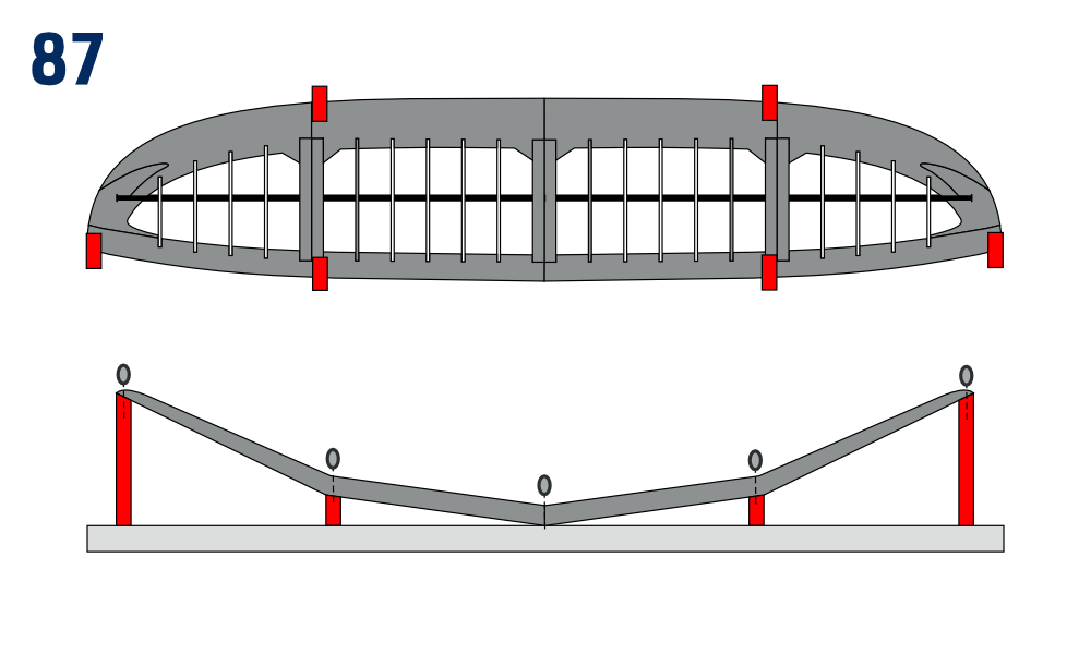
- Prepare the wing jig; glue the P14 and P15 balsa blocks to a flat board. The jig allows to „build in“ the required washout/washin (Fig. 80) and will keep the wing warped in the desired way whilst the dope is curing. (Fig. 87)
Apply a coat of thin shrinking dope (diluted 1:1) to the entire surface of the wing; leave it to dry a little bit. Once the dope is not sticky anymore, put the wing onto the jig and secure by modelling pins. Leave it pinned down until the dope is cured completely (depending on dope 12–24 hours). In total, apply 3 coats of thin shrinking dope and then 3 coats of thin protective dope. Lightly sand every layer (except for the last one) with No. 400–600 sand paper. You can apply the stickers then.
Final assembly
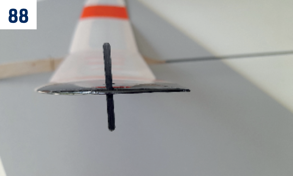
- Cut the covering film/tissue over the hole for the K9 launching pin; on the left wing panel for right handed pilots, on the right wing panel for left handed pilots. Round the edges of the pin and insert it into the wing (centred). (Fig. 88)
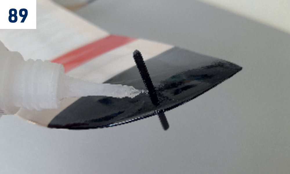
- Glue the pin with thin cyano from bottom and top sides, then apply CA accelerator. (Fig. 89)
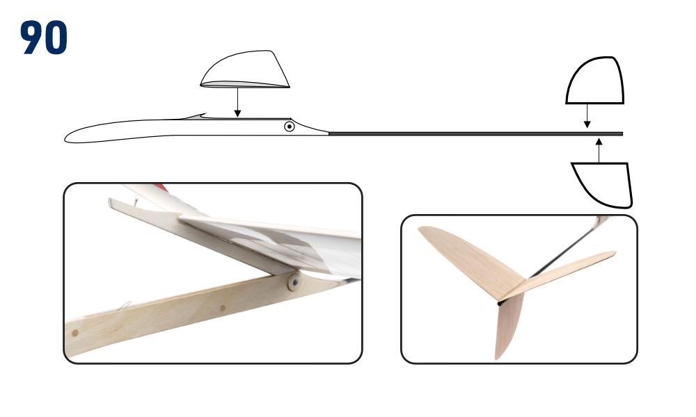
- Remove the covering film from the bottom of the wing centre (applies to the iron-on film covered wing only) and use 5min epoxy to glue the wing to the wing seat. Pin the wing down until the glue sets. Double check the correct alignment! Sand a narrow flat strip on the bottom of the centre of the horizontal tailplane. Apply thick cyano and attach the horizontal tailplane to the tail boom. Check the correct alignment relative to the wing and fuselage looking from above and from behind. Once satisfied, apply accelerator to cure the glue instantly. Glue the vertical fin in place in the same manner. (Fig. 90)
Pre-flight preparation
Centre of gravity and balancing
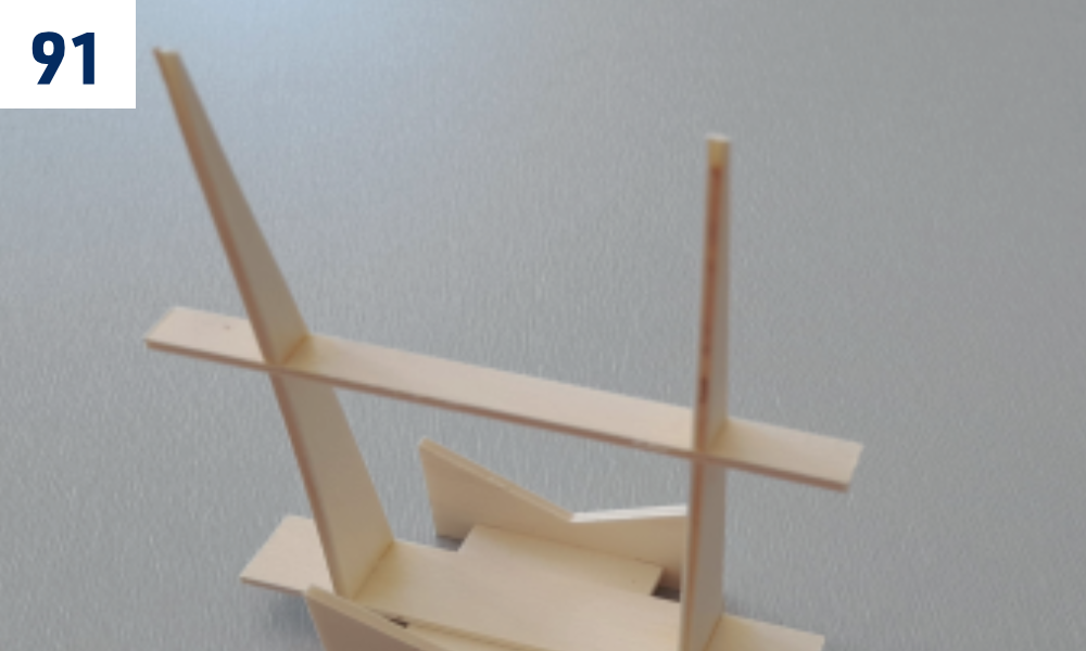
- Glue the bevel jig (Fig. 47) onto the tailplane jig (Fig. 20) to make a balancing cradle. Use thick cyano. (Fig. 91)
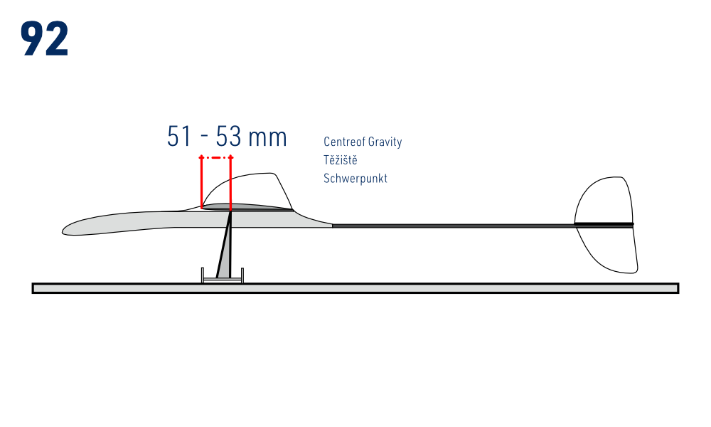
- Mark the centre of gravity 51–53 mm behind the wing leading edge on the bottom of the wing. Balance the model thoroughly; seal the ballast opening with a strip of clear sticky tape. (Fig. 92)
Flight trimming
This free-flight model has no radio-controlled surfaces. Adjust the wing incidence with the M2 screw and trim the fin as described below. Keep the wing twist settings for the chosen launching hand.
Flying
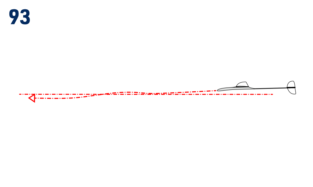
- Once the position of the centre of gravity has been set, you can launch your Vinx for the first time. Launch it with hearty push with the nose slightly down; it should glide smoothly, just with little swing. Fine tune the gliding path with the M2 setting screw in the fuselage. Pitching the wing up causes lifting the model up. (Fig. 93)
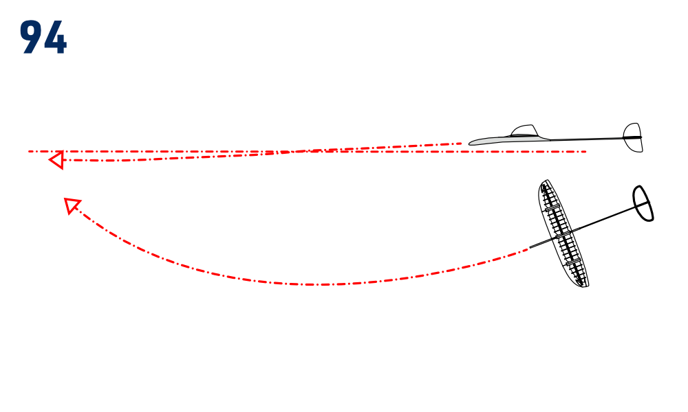
- Slightly bend the vertical fin to the right (looking from the tail to nose). Once launched, the model should glide smoothly in a wide right turn (this applies to right handed pilots). (Fig. 94)
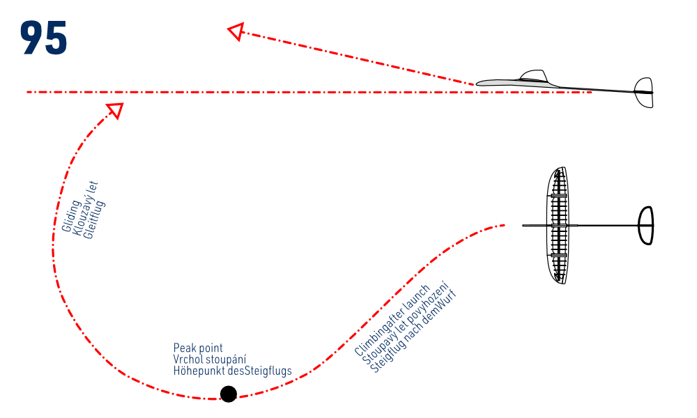
- Grasp the left wing with your right hand and hook your index and middle fingers on the pin. Launch the model in a discus style with a hearty push. If the model swings, adjust the wing pitch or reduce the diameter of the turn by bending the fin more to the right. If the model flies in circles and swings during the glide, it is necessary to add a little bit more ballast to the nose. (Fig. 95)
Have a ball, enjoy your Vinx!
Appendix
Assembly illustrations
Please note the pictures are just for illustration only – some show our prototype that might differ slightly from the actual, regular series production kits.
Fuselage

Tail


Wing

Parts list
| No. | Part | Material | Quantity |
|---|---|---|---|
| T1 | Nose | Plywood 4 mm | 1 |
| T2 | Fuselage | Liteply 4 mm | 1 |
| T3 | Wing Seat | Plywood 4 mm | 1 |
| T4 | Fuselage Side | Plywood 1 mm | 2 |
| T5 | Tail boom | Carbon tube Ø4 mm | 1 |
| T6 | Pin | Beech dowel Ø4 mm | 2 |
| T7 | Ring | Plywood 1 mm | 1 |
| T8 | Wing Seat Pin | Carbon Ø4 mm | 1 |
| T9 | Ring | Plywood 1 mm | 1 |
| T10 | Spring | Wire Ø0.5 mm | 1 |
| T11 | Pin | Nail 12 mm | 1 |
| T12 | Wing Setting Screw | M2 screw | 1 |
| T13 | Ballast | 1 bag | |
| T14 | Rubber Ring | 1 | |
| O1 | Vertical Fin | Balsa 1 mm | 1 |
| O2 | Horizontal Tailplane | Balsa 1 mm | 1+1 |
| K1 | Leading Edge | Balsa 8 mm | 1+1+1+1 |
| K2 | Trailing Edge | Balsa 3 mm | 1+1 |
| K3 | Wing Tip | Liteply 3 mm | 2 |
| K4 | Reinforcing Plate | Balsa 3 mm | 2 |
| K5 | Wing Main Spar | Carbon tube Ø2 mm | 2+2 |
| K6 | Centre Rib | Balsa 8 mm | 6 |
| K7 | Wing Rib | Balsa 2 mm | 10 |
| K8 | Wing Panel Rib | Balsa 2 mm | 8 |
| K9 | Launching Pin | Fibreglass 1.5 mm | 1 |
| K10 | Template 3 | Liteply 3 mm | 1 |
| K11 | Template 2 | Liteply 3 mm | 1 |
| K12 | Template 1 | Liteply 3 mm | 1 |
| K13 | Template 0 | Liteply 3 mm | 1 |
| P2 | Jig - Tail | Liteply 3 mm | 2 |
| P3 | Jig - Tail | Liteply 3 mm | 1 |
| P11 | Jig - Bevelling | Liteply 3 mm | 2 |
| P12 | Jig - Bevelling | Liteply 3 mm | 1 |
| P13 | Jig - Bevelling | Liteply 3 mm | 1 |
| P14 | Jig - Wing | Balsa 7×10×30 mm | 4 |
| P15 | Jig - Wing | Balsa 7×10×80 mm | 2 |
| Building Plan | 1 | ||
| Stickers | 1 | ||
| Instruction Manual | 1 |