KAVAN Tara 1100mm - Instruction manual
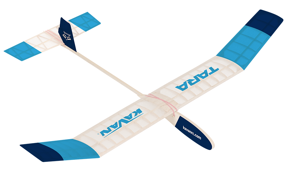
KAVAN Tara A1 - kit
Introduction
The F1H (A1) glider Tara is a great entry level kit for any modeller who has already gained some skills in the classic balsa construction and tissue covering. You will need some basic modeller's tools, glues and dopes – you will find these handy with any of your future projects as well. Please make yourself familiar with the building plans and this manual BEFORE you actually start the assembly.
Before you start
- If you are new to model aircraft, ask an experienced modeller to check your completed model and help you with the first flights. Your model shop or local model flying club can help you find an instructor.
- Build the model according to these instructions. Do not alter or modify it, as this can make it unsafe or unable to fly. Take time to build everything straight, true and strong.
- Check the kit for missing or damaged parts before starting. Familiarise yourself with each component and contact your dealer immediately if a replacement is needed.
- Trial fit every part before gluing. Check that you have the correct part and that it fits properly; extra glue cannot compensate for a poor fit.
- Use the centre of gravity (CG) position marked on the supplied building plan. Balance the model before the first flight as described in Pre-flight preparation.
Check the contents and report missing or damaged parts before starting construction.
Safety precautions
This model is not a toy. Even though it is light and slow in flight, incorrect handling can cause injury or damage. Build, test and fly it responsibly, following the instructions, applicable model flying safety rules and common sense.
Use suitable tools and accessories in good condition. Install all parts correctly and check the model before the first and every subsequent flight. Do not fly a damaged model. Beginners should fly with help from an experienced modeller.
Children under the age of 14 must operate the model under adult supervision. Fly in calm weather or a light breeze at a safe site away from obstacles.
Features
- High-performance gliding
- Extensively pre-processed
- Designed for A1 (F1H) competition
- Designed and manufactured in the Czech Republic
- Classical lightweight balsa construction
- Ideal as a first full glider model
Technical specifications
| Parameter | Value |
|---|---|
| Wingspan | 1100 mm |
| Length | 828 mm |
| All-up weight | 225 g (minimum 220 g) |
Set contents
CNC-cut balsa parts of fuselage, wing and tail, hardwood sticks, sand paper, ballast, rubber band, adjustable side tow hook, white covering tissue, stickers, full size building plan and instruction manual.
Recommended glues
Use a solvent-based modelling glue (UHU® Hart, Kanagom or similar), water-resistant white glue (KAV56.9960 / KAV56.9961, BISON Super Wood or similar), or medium cyanoacrylate glue (KAV56.9952).
Recommended dopes
For tissue covering, use KAVAN Standard adhesive dope (KAV56.9988), shrinking dope (KAV56.9986) and matching thinner (KAV56.9992). KAVAN Color coloured shrinking dopes (KAV56.9987.x) may also be used.
Tools and accessories
Prepare a perfectly flat building board that accepts pins (at least 300×700 mm), a modelling knife (KAV66.770) with no. 11 blades, a fretsaw with fine blades, sanding blocks with 180 and 360–400 grit sandpaper, modelling pins (KAV66.0355), scissors, flat and round needle files and a soft flat 1/4"–3/8" brush. Protect the plan with thin clear plastic film; a large polyethylene bag cut open is suitable. Prepare drill bits for the dowel and ballast holes specified in the assembly instructions.
Main section
Building plan
Use the full-size plan supplied with the kit to identify parts, profiles, dihedral, tailplane incidence and the centre of gravity (CG). The lettered details referenced below are on that plan. Keep the paper plan available throughout assembly and balancing.
Assembly
- Lay the wing building plan on the building board and put a sheet of a thin clear plastic film to protect the building plan. If you have got just a small building board, you can carefully cut the building plan into sections – wing section, horizontal tailplane section etc.
- Before you apply the glue, please, always double-check the correct size, shape and alignment of the particular part.
- Balsa and spruce sticks are intentionally supplied oversized in the kit. Pin the stick to the plan overlapping at both ends – you will cut/sand them to the correct length/shape once the assembly of the particular part has been finished.
Wing
- The plan shows the centre section and both outer panels, which may be built simultaneously. Pin the left trailing edge 3a to the plan with at least three pins, aligning its notches with the drawn ribs. Place the right trailing edge 3b against it and check all notches. Shorten the right piece if necessary, then glue the two pieces together and pin them down. Lightly sand the CNC-cut ribs 1 to remove imperfections (Det. G–G).
- Pin down the pre-shaped balsa leading edge 2. Glue the balsa ribs 1 in place. Fit, cut to size and glue the bottom sheeting 4, made from two 1.5mm balsa pieces, between the leading and trailing edge. Glue the three reduced-height ribs 6 onto the sheeting: one about 2 mm in from each outer edge and one in the centre. Glue the balsa end rib 5 in place – the bevelled side outwards (in similar manner to Det. F–F).
- Glue the wing main spar 7 (3×8 mm spruce stick) into the notches in the upper side of ribs (trim the bottom edges slightly to slip easier in). Glue only the bottom of the main spar to ribs 5. Insert partly the wing joiners 42 along the sides of the main spar in order to get the correct alignment in the wide notches (DO NOT glue the joiners yet!). Fit and glue the upper central sheeting 8 and 9 (Det. B–B) in place. Glue the corner gussets 10 to the leading and trailing edges. Apply some additional glue to all joints if necessary and let cure.
- Once the glue has cured thoroughly, remove the wing centre section from the building plan and sand the leading edge, trailing edge and main spar flush with the edge of the bevelled outer ribs 5. Sand the leading edge to shape (Det. D–D).
- The wing panels are to be built in the similar manner to the wing centre section. Pin the tapered balsa trailing edges 40 to the building plan carefully matching the pre-cut notches with the ribs drawn on the plan.
- Lightly sand the CNC milled balsa ribs 41–46 to remove any imperfections. Pin down the pre-shaped balsa leading edges 48. Glue the balsa ribs 41–46 in place. Bevel the front edge of the ribs in order to match the leading edge 48 perfectly. In similar manner, lightly sand the bevelled root ribs 47 to match the leading and trailing edges and glue them in place (Det. F–F).
- Glue the wing panel main spars 49 (3×8 mm spruce stick) into the notches in the upper side of ribs. Glue only the bottom of the main spar to ribs 47. Insert partly the wing joiners 42 along the sides of the main spar in order to get the correct alignment in the wide notches (DO NOT glue the joiners yet!). Trim the gussets 51 as necessary and glue in place. Apply some additional glue to all joints if necessary and let cure.
- Once the glue has cured thoroughly, remove the wing panels from the building plan and sand the leading edge, trailing edge and main spar flush with the edge of the bevelled root ribs 47. Glue the wing tips 50 in place. Once cured, sand them to shape. Sand the leading edge to shape (Det. D–D).
- Trial fit the wing centre section and wing panels – if attached together, the wing panel dihedral must be 100 mm (Det. E). Once satisfied, glue the plywood wing joiners 42 to the wing centre section main spar 7. Apply a generous amount of glue to wing centre section end ribs, wing panel root ribs and wing joiners 42 and attach the wing panels to the wing centre section. Lay the wing centre section down on the building board. Secure it with a couple of magazines wrapped in a plastic bag serving as a weight. Align the wing panels so their tips were 100 mm above the building board (you can use a couple of books or a wooden block). Let the glue cure thoroughly. Once cured, carefully sand the joints and the entire wing using sanding blocks with a coarse and then fine sandpaper to smooth any rough areas.
- The wing is now ready for covering.
Horizontal tailplane
- The horizontal tailplane is to be built directly on the plan protected with a clear plastic film in similar manner as the wing. Pin down the spruce trailing edge (3×5×405 mm) 11 overlapping on both two ends. Glue the balsa centre plate (3 mm – 30×80 mm) 13 to the trailing edge 11. Glue the spruce leading edges (3×5×197 mm) 10 to the centre plate and pin them down overlapping on both two ends. Cut to size and glue in place the diagonal ribs 12 made of 3×5 mm balsa stick. Start with the outer diagonal ribs first. Then proceed towards the centre of the horizontal tailplane.
- Glue the spruce main spar 14 (3×5×395 mm) to the top of the horizontal tailplane framework. Fit and glue the front balsa upper plate 16 (3 mm – 30×30 mm) and two rear plates (3 mm – 13.5×45 mm) 17. Align the outer edges of the plates 17 to match the bottom plate 13 leaving about 2.5 mm slot between them to fit the bamboo dowel 18 later. Sand the gussets 15 to fit and glue them in place.
- Once the glue has cured thoroughly, remove the horizontal tailplane from the building plan. With a sanding block, shape the tips and centre plates as indicated on the plans (Det. A–A). Round the leading and trailing edges and the tips (Det. A–A). The horizontal tailplane has been finished for now. Once covered with the tissue, glue the bamboo dowel (Ø2.5×50 mm) 18 between the plates 17 extending behind the trailing edge by 15 mm.
Fuselage and fin
- The fuselage consists of the tail boom made of spruce sticks and balsa blocks and the front fuselage block made of Ceiba plywood with poplar plywood side covers offering enough space for the ballast and timer (if you decided to install one).
- Start with the tail boom. Glue it on the building board in order to make the tail boom true and straight. Glue the front balsa block 20 to the spruce stick (2×8×595 mm) 22 taking care the outer edges of the block matched the edges of the stick.
The rear balsa block 21 will be glued to the bevelled side of the front block later.
- Now apply glue to the rear part of the spruce stick 22 and block 20. Attach the rear balsa block 21 matching the edges of the stick. Glue the other 2×8 mm spruce stick 23 to the tail boom.
- If you consider installing a timer (either mechanical or electronic) and dethermalizer, now is the time to trim the openings in the fuselage block 24 as needed. Do not forget to cut an appropriate opening in one of the side covers (26 or 28) as well.
- Insert the tail boom in the notch in the fuselage block 24. Trim the notch if necessary. Remove the tail boom, apply a generous coat of glue into the notch and insert the tail boom. Glue it on the building board in order to make the fuselage true and straight. Insert the two beech dowels 25 (Ø4×32 mm) into the fuselage – no glue yet. The dowels will help with the correct alignment of the side covers. Apply glue to the left side of the fuselage block. Align and attach the side cover 26. You can lay the fuselage down onto your building board and weigh the cover down to cure. Insert and glue the main ballast 27 into the nose opening. Glue the other side cover 28 in place.
- Glue the reinforcement plate 30 into the fin 29. Make the front horizontal tailplane seat. Glue the spruce stick (3×5×25 mm) 32 to the plywood plate (1 mm – 25×15 mm) 31.
- Mark the position of the tailplane seat to the fuselage according to the building plan and glue it to the tail boom. Lay the horizontal tailplane down on the seat in order to check the tailplane is square to the fuselage sides (when looking from the nose to the tail) and also square to the longitudinal axis of the fuselage (when looking from above). Glue the rear tailplane seat (balsa 1.5 mm – 8×10 mm) 33 to the fuselage. Glue the fin 29 to the fuselage. Use the horizontal tailplane as a reference again. The fin has to be square to the horizontal tailplane and exactly in the longitudinal axis of the fuselage. Round the leading and trailing edges of the rudder 52. The brass rudder hinges 53 will be installed after doping and covering of the model.
- Glue the plywood wing seat plate 36 to the fuselage, centred and square to the fuselage sides. Glue the beech wing hold-down dowels 25 into the fuselage. Mark and drill the holes for the horizontal tailplane hold-down dowels 34 and 35 (bamboo Ø2.5×25 mm) according to the plan, then glue the dowels in place. Glue the balsa ventral fin 37 to the underside of the fuselage.
Doping and tissue covering
Use glues, dopes and thinners in a well-ventilated area, away from flames, sparks and other ignition sources. Follow the product labels and avoid inhaling vapours or sanding dust.
- Lightly sand the entire airframe with the fine sand paper. Before the frames are covered, all EXTERNAL surfaces MUST be primed with the adhesive dope (diluted at least 1:1 with the thinner; the dope must have the viscosity of water - never use the dope unthinned!). Use a soft flat brush to apply the dope and, when dry, lightly sand all doped surfaces with the fine sandpaper. Apply the second coat, sand lightly again.
- Sheets of the Vlies covering tissue are supplied in the kit. You can glue it to the airframe using water thinned white glue or adhesive dope. Always align the „grain“ of the tissue the long way - from tip to tip of the wing or horizontal tailplane.
When attaching the covering with adhesive dope, brush thinned adhesive dope through the tissue over its entire surface after laying it on the frame. Allow it to dry before trimming the overlap. Use adhesive dope for attachment and shrinking dope only for the subsequent shrinking coats.
Horizontal tailplane
- If you are new to the dope and tissue business, you should start with the horizontal tailplane in order to gain the skills on smaller part of your model featuring no curves. Cut a piece of the tissue 10 mm oversized all around the outline of the horizontal tailplane. Apply the thinned white glue or adhesive dope around the external edges of the lower side of the tailplane and to the diagonal ribs and centre plate. IMMEDIATELY set the tissue in position and smooth the edges with fingertips before it has a chance to dry. Cut the tissue all around the outline of the tailplane leaving it 4–5 mm over size. Bend and glue with thinned white glue or clear dope the overlapping tissue around the entire tailplane.
- Cover the upper side of the tailplane in the same manner – apply thinned white glue/adhesive dope to the trailing and leading edges, main spar, centre plates and tips. Do not apply the glue to the diagonal ribs!
Wing
- Cut four or six pieces of the tissue 10 mm oversized all around the outline (do not forget the upper sheets have to be wider due to the airfoil camber). A skilled builder could cover the entire bottom side of the wing using just one long strip of tissue. The upper side of the wing centre section and wing panels are to be covered by separate strips. Again, start with the bottom side of the wing. Apply the glue/dope to the leading and trailing edges and all ribs. Attach the tissue and smooth the edges with fingertips. Cut the tissue all around the outline of the wing leaving it 4–5 mm over size. Bend and glue with thinned white glue or adhesive dope the overlapping tissue around edges of the entire wing. You will have to cut the tissue against the wing panels joints and in short 4–8 mm portions around the wing tip in order to follow the curve of the tip.
- Cover the upper side of the wing centre section in the same manner (the tissue overlapping over the wing panel root ribs 47). Apply thinned white glue/adhesive dope to the trailing and leading edges, main spar and ribs.
- Cover the wing panels with separate strips of tissue. Attach the tissue to the rib, using a pencil and steel ruler or a piece of flexible plastic draw the line marking the joint of 5 and 47 ribs on the tissue. Trim the tissue to the line and glue in place in the usual manner. You will have to cut the tissue in short 4–8 mm portions around the wing tip in order to follow the curve of the tip.
- You can cover the tail boom as well (apply 4 slightly overlapping strips to the bottom both sides and finally to the top of the boom) to add some extra strength. There is no need to cover the nose.
- Now you can apply several coats of thinned shrinking dope in order to shrink the tissue and protect it from moisture. Once the tissue is nice and smooth without wrinkles (after 1–2 coats) you can apply the colour tissue trim and continue in applying the shrinking dope.
- Only apply the dope in a dry and well ventilated area at room temperature (over 20 °C; low temperature/high humidity may cause „fogging“ of some dopes turning them milky white instead of clear. If that happens you can usually cure it by taking the model to a dry and warm place and applying just the fresh thinner with a brush to the „fogged“ part). Apply 3–5 coats of thinned dope to the entire model (use the top gloss dope for the fuselage and the last coat for the wing and horizontal tailplane). Lightly sand all doped surfaces with fine sandpaper between each coat.
- Apply the colour tissue trim to the fuselage before the last coat of top gloss dope (use the top gloss dope for the final coat). The stickers are to be applied only after the final coat!
- Let the model dry thoroughly after each coat (2–3 days). Check for any warping of the wing or horizontal tailplane. If that happens, you have to lay the wing and/or tailplane down to a flat surface protected with a plastic film and weigh it down (a couple of magazines in a plastic bag to the rescue again) after each coat. Let it dry thoroughly.
Pre-flight preparation
Secure the side towhook 39 to the left side of the fuselage using two screws 38 – refer to the building plan. The towhook is adjustable. You can move it forward on a windy day or backward on a calm day in order to achieve nice and steady climbing during the hi-start. Use the tip of a pointy modeller's knife to cut slots for the brass-sheet rudder hinges 53 into the fin 29 and rudder 52. Cyano the hinges into the rudder and then into the fin leaving a slight gap between the fin and rudder. Tie the wing and horizontal tailplane to the dowels on the fuselage using several loops of the supplied rubber thread.
One loop is never enough!
Drill 5 mm access hole into the additional ballast compartment in the fuselage (refer to the building plan). Support the wing of the model with your fingertips in the centre of gravity position (the point marked by an arrow on the fuselage plan). The fuselage should be level - if the nose pitches up put in as much of additional ballast (not supplied in the kit) as necessary (you can use pellets, small screws etc.) Once satisfied, cover the hole with a strip of clear sticky tape.
The correct balancing is essential. Incorrectly balanced model will be difficult to set up or unable to fly at all!
Flying
Once again check the correct position of the centre of gravity, check for any excessive warping of the wing, tailplane and fuselage. Choose a nice calm day for the first flight.
The model must be launched into the wind every time. Throw grass into the air to observe the wind direction. Hold your model with the wing and fuselage level. Launch your model with a gentle push straight with the nose pointing slightly down. Do not throw your model with nose up, or at greater angle than 10° down. The model must have a certain minimum speed from the very start to stay airborne. It is not enough to just place your model in the air. It is better to land in tall grass in order to prevent any damage to your model during initial trimming.
If everything is OK (correct wing and tailplane alignment, correct CG position) Tara will fly with the wings level in a nice glide with her nose pointing slightly down. If the model glides straight down to the earth a few paces in front of you, check the CG position again. If OK, add a thin piece of balsa or plywood under the trailing edge of the horizontal tailplane until the model glides in a nice flat and straight path.
If the model repeatedly pitches up and stalls, add nose ballast gradually, recheck the CG against the plan and repeat gentle test glides. Do not attempt a tow launch until the glide is stable.
Once satisfied, bend the rudder 52 slightly (about 2 mm) to the left (looking from the tail to the nose). Now the model should glide in large left (counter clockwise) turns; whilst under tow, the off-centre tow hook would force your Tara right - resulting in straight flight.
Once trimmed out you can try your first hi-start with your Tara using 25–50 m towline (a fishing line). You can purchase a towline set in your local model hobby shop or you can make your own from scratch. Get a towline (any fishing line strong enough to hold 5 kg fish is OK), tie a key ring to one end (bowline knot is the best) and a flag (a piece of red cloth) 20–30 cm from the end. The flag makes the towline visible in the air as well as on the ground. Find a suitable spool to keep the towline on.
Hook the ring at the towhook and ask a friend to hold (and launch later) your model. Unwind the towline walking into the wind keeping it slightly stretched. The launch position of the model: wings level, nose very slightly up, directly into the wind.
Give a signal to your friend holding your model. Both of you will start running into the wind, the assistant will launch the model after a few paces. Continue running into the wind paying attention to the tension of the towline and checking the model over your shoulder. Run as fast as necessary to achieve steady climbing rate of your model. The model should climb straight forward, at steady rate, in a nice arc. The stronger the wind, the slower you might run. If the towline tension decreases, your model climbs slowly (and yaws to a side) you should run faster. If the towline tension increases and the model violently turns to a side, you have to slow down and wait until the model returns to the original straight path. Hi-start requires some skills. Especially on a windy day running too fast might even end in destruction of your model. Once the model climbs almost over your head, it should start turning slightly left – this is the moment to stop. Let the model fly in front of you and release the towline.
For the initial high start, set the tow hook to the forward position. Based on the Tara's behaviour you can move it back/adjust later. If your model hesitates to climb, move it back. If pitches the nose up and veers to side, move it forward. Adjust the rudder to achieve large flat left turns; tight banked turns kill the altitude! Usually, just 2 mm left offset is OK. Contest flyers would want to install the dethermalizer with a timer that kicks the horizontal tailplane up (about 45°) once the set time has elapsed; the model will land in large „hoops“ then.
Appendix
Parts list
Main parts
| Part | Building plan no. | Quantity |
|---|---|---|
| Fuselage block – 8 mm ceiba plywood | (24) | 1 |
| Side cover – 3 mm poplar plywood | (26, 28) | 2 |
| Vlies tissue sheet (1230×330 mm) | 1 | |
| Vlies tissue sheet (200×410 mm) | 1 | |
| Colour tissue trim sheet | 2 | |
| Sand paper | 1 | |
| Building plan | 1 | |
| Instruction manual | 1 |
Stick bundle A
| Part | Building plan no. | Quantity |
|---|---|---|
| Fuselage stick - spruce 2×8×595 mm | (22, 23) | 2 |
| Wing leading edge - balsa 8×8×645 mm | (2) | 1 |
| Wing main spar - spruce 3×8×645 mm | (7) | 1 |
Stick bundle B
| Part | Building plan no. | Quantity |
|---|---|---|
| Wing leading edge - balsa 8×8×260 mm | (48) | 2 |
| Wing trailing edge - balsa 14×4.7×330 mm | (3a, 3b) | 2 |
| Wing trailing edge - balsa 14×4.7×260 mm | (40) | 2 |
| Spruce stick 3×5×405 mm | (11) | 1 |
| Spruce stick 3×5×395 mm | (14) | 1 |
| Spruce stick 3×5×197 mm | (10) | 2 |
| Spruce stick 3×8×245 mm | (49) | 2 |
| Balsa fuselage block – thick | (20) | 1 |
| Balsa fuselage block – thin | (21) | 1 |
| Balsa stick 3×5×300 mm | (12) | 6 |
Rib set bundle A
| Part | Building plan no. | Quantity |
|---|---|---|
| Main wing rib | (1) | 14 |
| Support rib | (6) | 3 |
| Wing end rib (bevelled) | (5) | 2 |
Rib set bundle B
| Part | Building plan no. | Quantity |
|---|---|---|
| Wing panel root rib (bevelled) | (47) | 2 |
| Wing tip | (50) | 2 |
| Wing panel rib | (41–46) | 12 |
Bundle C
| Part | Building plan no. | Quantity |
|---|---|---|
| Fin | (29) | 1 |
| Bottom fin | (37) | 1 |
| Wing seat plate – plywood 1.5 mm | (36) | 1 |
Wing set bundle D
| Part | Building plan no. | Quantity |
|---|---|---|
| Balsa plate – Balsa 3 mm – 30×80 mm | (13) | 1 |
| Balsa plate – Balsa 3 mm – 30×30 mm | (16) | 1 |
| Balsa plate – Balsa 3 mm – 13.5×45 mm | (17) | 2 |
| Wing joiner „V“ | (42) | 4 |
| Gusset | (10, 15, 51) | 18 |
Small parts bundle E
| Part | Building plan no. | Quantity |
|---|---|---|
| Rudder | (52) | 1 |
| Fin reinforcement plate | (30) | 1 |
| Rear horizontal tailplane seat – Balsa 1.5 mm – 8×10 mm | (33) | 1 |
| Towhook | (39) | 1 |
| Rubber thread Ø1×600 mm | 1 | |
| Horizontal tailplane seat – plywood 1 mm – 25×15 mm | (31) | 1 |
| Spruce Stick – 3×5×25 mm | (32) | 1 |
| Bamboo dowel Ø2.5×25 mm | (34, 35) | 2 |
| Bamboo dowel Ø2.5×50 mm | (18) | 1 |
| Beech dowel Ø4×32 mm | (25) | 2 |
| Screw 2×8 mm | (38) | 2 |
| Ballast Ø26×8 mm | (27) | 1 |
| Rudder hinge (brass-sheet) | (53) | 2 |