KAVAN Robin 495mm - Instruction manual
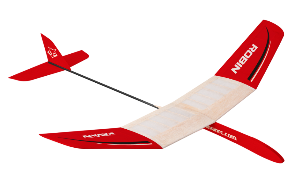
KAVAN Robin - kit
Introduction
The Robin is a contest hand launch glider (HLG) for beginners who already have some experience building simple gliders. Its built-up balsa wing and tissue covering introduce traditional model-building techniques. An experienced HLG flyer can help you trim it for competition performance. You will need basic modelling tools, glues and dopes, which will also be useful for future projects. Read this manual and study the supplied building plan thoroughly before starting assembly.
Before you start
- If you are new to model aircraft, ask an experienced modeller to check your completed model and help you with the first flights. Your model shop or local model flying club can help you find an instructor.
- Build the model according to these instructions. Do not alter or modify it, as this can make it unsafe or unable to fly. Take time to build everything straight, true and strong.
- Check the kit for missing or damaged parts before starting. Familiarise yourself with each component and contact your dealer immediately if a replacement is needed.
- Trial fit every part before gluing. Check that you have the correct part and that it fits properly; extra glue cannot compensate for a poor fit.
- Use the centre of gravity (CG) position marked on the supplied building plan. Balance the model before the first flight as described in Pre-flight preparation.
Your dealer cannot accept kits for return if construction has begun.
Safety precautions
This model is not a toy. Even though it is light and slow in flight, incorrect handling can cause injury or damage. Build, test and fly it responsibly, following the instructions, applicable model flying safety rules and common sense.
Use suitable tools and accessories in good condition. Install all parts correctly and check the model before the first and every subsequent flight. Do not fly a damaged model. Beginners should fly with help from an experienced modeller.
Children under the age of 14 must operate the model under adult supervision. Fly in calm weather or a light breeze at a safe site away from obstacles.
Features
- High-performance hand launch glider
- Designed and manufactured in the Czech Republic
- Extensively pre-processed parts
- Easy to build
- Good flight characteristics
Technical specifications
| Parameter | Value |
|---|---|
| Wingspan | 495 mm |
| Length | 500 mm |
| All-up weight | 32 g |
Set contents
CNC-cut balsa parts, accessories, ballast, covering tissue, stickers, full-size building plan and instruction manual. See the Parts list for the individual components.
Recommended glues
Use a solvent-based modelling glue (UHU® Hart, Kanagom or similar), water-resistant white glue (KAV56.9960 / KAV56.9961, BISON Super Wood or similar), or medium cyanoacrylate glue (KAV56.9952).
Recommended dopes
For tissue covering, use KAVAN Standard adhesive dope (KAV56.9988), shrinking dope (KAV56.9986) and matching thinner (KAV56.9992 / KAV56.9992A). KAVAN Color coloured shrinking dopes (KAV56.9987.x) may also be used.
Tools and accessories
Prepare a perfectly flat building board that accepts pins (at least 150×700 mm), a modelling knife (KAV66.770) with no. 11 blades, a fretsaw with fine blades, sanding blocks with 180 and 360–400 grit sandpaper, modelling pins (KAV66.0355), scissors, flat and round needle files and a soft flat 1/4"–3/8" brush. Protect the plan with thin clear plastic film; a large polyethylene bag cut open is suitable. A drill is needed for the ballast access hole described below.
Main section
Building plan
Use the supplied full-size plan to identify the parts, rib stock, wing profile, dihedral and CG mark. Details A–A, B–B and C–C are on this plan. (Fig. 1)
Assembly
Wing centre section
- Lay the plan on the flat building board and cover it with thin clear plastic film. Pin the right leading edge (1) and trailing edge (2) to the plan with their flat faces down.
- Cut the outer ribs (3) from the bevelled balsa stock no. 2. Glue them between the leading and trailing edges with the bevel facing outward and upward to form the outer-panel dihedral. (Detail A–A)
- Cut centre rib (4) to length from balsa stock no. 4 and glue it in place.
- Cut ribs (5) from balsa stock no. 6 to fit the slots in the leading and trailing edges, then glue them in place.
- Once the glue has cured, lift the centre section off the board and coat it with adhesive dope thinned 1:1 with its matching thinner. Allow it to dry thoroughly, then sand to the airfoil shown on the fuselage side view, using coarse and then fine sandpaper. (Fig. 1)
- Build the left centre section in the same way.
Outer wing panels
- Pin the right panel's trailing edge (6) to the film-covered plan. Glue wing tip (7) to it, then glue leading edge (8) in place with its flat face down.
- Cut root rib (9) from bevelled balsa stock no. 2 and glue it between the leading and trailing edges, with the bevel facing outward and upward. (Detail A–A)
- Cut ribs (10) from balsa stock no. 6 and glue them into the leading- and trailing-edge slots and against the inside of the wing tip.
- Once dry, lift the panel off the board and coat it with adhesive dope thinned 1:1 with its matching thinner. Allow it to dry thoroughly, then sand to the airfoil, using coarse and then fine sandpaper.
- Build the left outer panel in the same way.
Fuselage
- On a flat board, glue nose (16) to fuselage (14). Glue upper stick (17) in place and lower stick (15) into the underside groove.
- Use cyanoacrylate glue to fit fin (22) into the slot in carbon tail boom (18), centred in the tube. (Detail C–C)
- Lay horizontal tailplane (23) on the board. Apply 2–3 small drops of cyanoacrylate between its marked centre lines. Attach the boom and fin so the fin is perpendicular to the tailplane, the boom lies exactly between the lines and the tailplane's trailing edge extends 8 mm beyond the boom end.
- Check the alignment, then apply medium cyanoacrylate along both sides of the entire boom-to-tailplane joint.
- Stand the front fuselage perpendicular to the film-covered board with nose (16) extending freely beyond the board edge. Pin it in place. Lightly roughen the boom's contact area with sandpaper and tack it to the front fuselage with 2–3 small drops of medium cyanoacrylate.
- Check that the fuselage is straight and the whole horizontal tailplane lies flat on the board. Remove the assembly from the board and apply medium cyanoacrylate along both sides of the entire boom-to-fuselage joint.
- Glue ballast (20) into the nose. Glue side covers (19) and (21) in place, flush with the fuselage outline.
Joining the wing
- Sand and match the mating ribs of both centre sections and outer panels so they fit accurately at the dihedral shown on the plan. (Detail B–B)
- Pin one centre section flat to the film-covered board. Apply glue to the root rib of the other section and join them. Support the outer rib of the raised section by 12 mm, using two 6mm balsa offcuts (25). (Detail B–B)
- Cut a 40mm dihedral jig (26) from the remaining balsa stock no. 4.
- Apply glue to the outer panel's root rib and join it to the centre section pinned to the board. Support the wing tip with jig (26). Attach the other outer panel in the same way.
Priming the airframe
- Lightly sand the whole airframe with fine sandpaper.
- Before covering, prime all external surfaces with adhesive dope diluted with at least an equal quantity of matching thinner (1:1). It should flow like water; never use undiluted dope for this priming step.
- Apply the dope with a soft flat brush. Allow it to dry, then lightly sand all coated surfaces with fine sandpaper. Apply a second coat and sand lightly after drying.
Tissue covering
- Begin with the underside of the wing, including the centre section and outer panels. Cut the tissue with a 5–8mm margin around each area. Run the tissue grain along the wing, parallel to the leading edge, rather than across it.
- Brush undiluted adhesive dope around the lower frame's perimeter. Immediately place the tissue and smooth it onto the frame, keeping an even overlap all around.
- Brush thinned adhesive dope over the entire exposed tissue surface and smooth the edges again. Allow the dope to dry before trimming.
- Once dry, trim the tissue to a 3–4mm overlap. Fold the overlap around the leading and trailing edges and attach it with thinned adhesive dope. Cut the overlap at the panel joints and into 4–8mm sections around curved tips so it follows the outline.
- Cover the upper surfaces of the outer panels and centre section in the same way.
- Attach any coloured tissue decorations to the wing and other model parts with dope. Apply two to three coats of thinned shrinking dope to the covered wing. Allow each coat to dry and lightly sand the coated surfaces with fine sandpaper.
Apply dope outdoors or in a well-ventilated, dry room at a temperature above 20 °C.
Low temperature or high humidity can make some dopes turn milky white. Moving the model to a warm, dry place and carefully brushing the affected area with fresh compatible thinner will usually clear this clouding. Apply stickers only after the final dope coat.
Final assembly
- Centre the wing on the fuselage and glue it in place with UHU® Hart or medium cyanoacrylate. Viewed from the front, its dihedral must be symmetrical relative to the horizontal tailplane; viewed from above, the wing must be perpendicular to the fuselage.
- Taper support triangle (11) to fit and glue it between the underside of the right wing half and the fuselage side. (Detail B–B)
Pre-flight preparation
- Drill a Ø4–5mm access hole into the additional-ballast compartment shown on the fuselage plan. (Fig. 1)
- Support the wing with your fingertips at the CG position marked ⌖ on the plan. The fuselage should remain level. If the nose rises, add enough ballast to the compartment to obtain this balance. Small pellets or screws are suitable; this additional ballast is not supplied.
- Seal the access hole with clear adhesive tape so the ballast cannot escape.
- Glue the fine-sandpaper grip strips (27) to both sides of the fuselage for a secure hand-launch grip.
Use the CG mark on the supplied building plan.
Flying
Choose a calm, windless day, preferably in the evening, for the first flights. Use a flat grassy site with no buildings, cars, power lines or other obstacles within 50–100 m. A local model flying club can provide a suitable field, advice and help.
Hand launch and initial trimming
- Launch directly into the wind every time. Throw a few blades of grass into the air to check its direction; a ribbon on a suitable pole can also indicate the wind.
- Hold the model under the wing with the wings level. Give it a gentle, straight push with the nose pointing slightly down. Never launch nose-up or more than 10° nose-down. The model needs enough forward speed to fly; simply placing it in the air is insufficient.
- Use tall grass for the first trimming flights to help prevent damage. With the wing, tail and CG correctly set, the model should glide smoothly with level wings and the nose slightly down. Adjust the tail surfaces if necessary.
- If it dives and lands a few paces ahead, carefully bend the horizontal tailplane's trailing edge slightly up. Repeat the test and increase the adjustment only as needed for a smooth glide.
- If it climbs and stalls or repeatedly pitches up and down, bend the horizontal tailplane's trailing edge slightly down.
- Viewed from behind, if the model turns right, bend the rear of the fin slightly left; if it turns left, bend it slightly right. Repeat the tests until the glide is smooth.
Competition trimming requires experience and repeated testing. Study specialist model-flying handbooks, magazines and online guidance, and seek help from an experienced HLG competitor at a local club.
Appendix
Parts list
| Part | Building plan no. | Quantity |
|---|---|---|
| Wing leading edge | (1) | 2 |
| Wing trailing edge | (2) | 2 |
| Wing panel leading edge | (8) | 2 |
| Wing panel trailing edge | (6) | 2 |
| Wing tip | (7) | 2 |
| Nose | (16) | 1 |
| Side cover | (19, 21) | 1+1 |
| Tail boom (carbon Ø4 mm) | (18) | 1 |
| Fuselage reinforcement stick (spruce 2×5×105 mm) | (15) | 1 |
| Fuselage upper stick (spruce 3×5×175 mm) | (17) | 1 |
| Fuselage | (14) | 1 |
| Horizontal tailplane | (23) | 1 |
| Vertical tailplane | (22) | 1 |
| Support triangle | (11) | 1 |
| Bevelled balsa stick, no. 2 (7×7 mm) | (3), (9) | 2 |
| Balsa stick 7×10 mm, no. 4 | (4), (26) | 1 |
| Balsa stick 7×1.5 mm, no. 6 | (5), (10) | 6 |
| Ballast (rod) | (20) | 1 |
| Anti-slip strip | (27) | 2 |
| Covering tissue | 1 | |
| Building plan | 1 | |
| Instruction manual | 1 |
Manufacturer's responsibility
As the kit manufacturer, we supply a high-quality kit and detailed instructions. The flight characteristics and performance of the finished model depend on how you build it. Since we cannot control how you complete and operate the model, we cannot assume responsibility for damage caused by or related to the operation of your completed model.