KAVAN FunStik 1280mm - Instruction manual
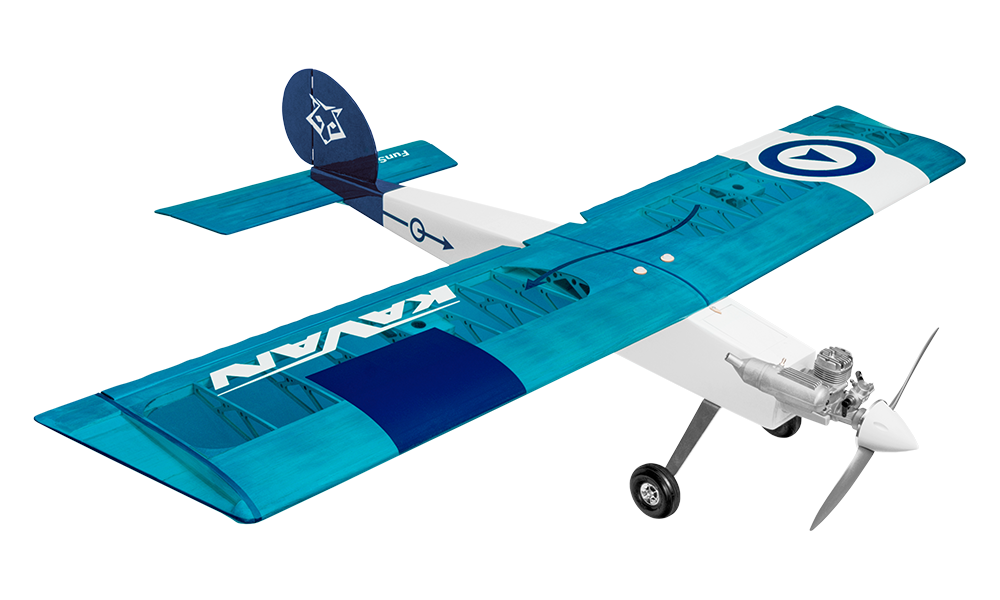
KAVAN FunStik - kit
Introduction
FunStik is a retro-style aerobatic high-wing model with a symmetrical wing section, designed and manufactured in the Czech Republic. The laser-cut balsa and light-plywood kit is intended for modellers with building experience who can already fly an aileron-equipped trainer. Fit a .21–.25 (3.5–4.0 cm³) glow engine or a 500–600 W brushless motor.
Before you start
- If you are not an experienced RC pilot, plan to have a fully competent pilot check your completed model and help you with your first flights. Even though we have tried to provide you with a thorough instruction manual, RC models are rather complicated, and an experienced modeller can quickly check over your model to ensure your first flights are successful.
- Please assemble your model according to these instructions. Do not modify or change your model in any way. Doing so may adversely change its flying characteristics.
- Before you begin, check the entire contents of this kit to make sure no parts are missing or damaged. It will also help you to become familiar with each component of your plane. If you find that any of the parts are either missing or damaged, contact your dealer immediately for replacement.
- Trial fit each part before glueing it in place. Before assembling, make sure you are using the correct part and that it fits well. No amount of glue can make up for a poorly fitting part.
- The supplied building plan marks the Centre of Gravity (CG); the control throws are listed in the pre-flight section. Please note it is essential to keep the recommended CG position for the first flight, or the model could be unstable, hard to control or even unable to fly. Later, you can fine-tune the CG position to suit your flying style and skills.
Precautions
This RC model is not a toy. Use it with care and strictly following the instructions in this manual.
Assemble this model following strictly these instructions. DO NOT modify or alter the model. Follow the instructions to obtain a safe and solid model at the end of the assembly.
Young pilots must operate the model under the supervision of a competent adult.
Make sure the model is in perfect condition before every flight, check that all the equipment works correctly and that the model is undamaged in its structure.
Fly only on days with a light breeze and in a safe place away from any obstacles.
This RC model you will build and fly is not a toy! Although it may seem light and slow in flight it is capable of serious bodily harm and property damage. It is your responsibility and yours alone to build this model correctly, properly install RC equipment and motor, test the model and fly following all safety standards (and common sense) as set down in Safety Codes valid in your country. If you are just starting RC modelling, consult your local hobby shop or an experienced modeller in your local RC club to find a good instructor.
You must build the model according to the instructions. Do not alter or modify the model, as doing so may result in an unsafe or unflyable model. Take time to build straight, true and strong. Use proper radio and other equipment that is in first-class condition, properly install all the components and test their correct operation before the first and any further flight. Fly the model only with competent help from a well-experienced modeller if you are not already an experienced RC pilot.
Features
- For brushless motor or glow engine
- Designed and manufactured in the Czech Republic
- Classical light build
- Extensively pre-processed
- Symmetrical wing profile
Technical specifications
| Wingspan | 1280 mm |
|---|---|
| Length | 1040 mm |
| All-up weight | 1450–1500 g |
| Wing area | 31.5 dm² |
| Wing section | Symmetrical |
| Controls | Aileron, rudder, elevator, throttle |
Kit contents
Laser-cut balsa and plywood parts, spruce spars, balsa strips and sheeting, hardware, aluminium-alloy main undercarriage, lightweight wheels, decals, building plan and instruction manual. The power system, radio equipment and covering material are not included.
Recommended power system & RC equipment
Use at least a four-channel radio. The catalogue recommends a 50–60 A ESC and a 3S LiPo battery with a capacity of 2200–2600 mAh for the electric version. Standard elevator and rudder servos should provide 3–4 kg·cm torque; smaller servos with comparable torque can reduce the weight of the electric version. Use quality micro servos for the ailerons and glow-engine throttle. The table gives example equipment.
| Component | Electric | Glow engine |
|---|---|---|
| Motor/Engine | KAVAN C3542-1250 | O.S. MAX-25FX II |
| Propeller | APC 10×6E (10×6″) | 9×5″–9×6″ |
| ESC | KAVAN R-50SB | - |
| Fuel tank | - | 100–170 ml* |
| Battery | KAVAN LiPo 11.1 V 2200 mAh 40/80C | NiMH 4.8 V 2000 mAh |
Recommended servos
| Control | Electric | Glow engine |
|---|---|---|
| Ailerons | 2× GO-13MG | 2× GO-13MG |
| Elevator & rudder | 2× GO-52MG (2× GO-17MG) | 2× GO-52MG |
| Throttle | - | GO-6MG |
*) 100–150 ml fuel tanks (KAV50.1002 / KAV50.0027 / KAV50.0028) are good for regular .20–.25 engines, more powerful and „thirstier“ O.S. MAX-25FX II will be happier with 150–170 ml tank (KAV50.1003).
Recommended glues
Unless stated otherwise, use medium cyanoacrylate (CA) glue (KAV56.9952). D-box sheeting and wing ribs are better glued using a water-resistant white aliphatic resin, like our KAV56.9960/KAV56.9961 White Glue SUPER (alternatively, you can use this sort of glue for most of the wood-to-wood joints). The highly loaded parts (wing roots, wing main spars, firewall etc.) should be glued together using 30-minute (or slower) epoxy (KAV56.9965 / KAV56.9966 / KAV56.9967) offering high strength and enough time for the correct positioning.
Recommended covering material
Use lightweight iron-on film such as KAVAN covering film, ORACOVER® or ORALIGHT®. Follow the covering manufacturer’s instructions.
Tools and accessories
- Very sharp modeller’s knife (KAV66.770) with No. 11 blades
- Scissors
- Electric drill with drill bits
- Wire cutter
- Long nose pliers
- Screwdrivers
- Razor saw
- Sandpaper No. 80, 100, 180, 360–400
- Needle files
- Soldering iron and solder
- Clothes pegs, office clips or woodworking clamps
- Modeller’s pins (KAV66.0355)
- Epoxy mixing stick and vessel
- Masking tape, clear sticky tape
- Rubbing alcohol (for cleaning up excessive epoxy)
- Paper tissue or soft cloth (for cleaning up excessive epoxy)
- Straightedge with scale
- Square edge
- Thin clear plastic film (for protecting the building plan)
- Permanent marker
- Modeller’s sealing iron (KAV66.8335), heat gun (for covering)
- Lightweight balsa filler (KAV56.9980 / KAV56.9981 / KAV56.9982)
Main section
Model assembly
Wing
- Locate all the parts for one half of the wing. Sand to fit all plywood/light plywood parts, the inner leading edge, bottom and upper main spars 14 if necessary.
- One by one, insert all the wing ribs 1 to 4 into the light plywood main spar shear webbing 15.
- Insert the inner leading edge, bottom and upper main spars 14 and the trailing edge shear webbing 16 into respective notches in the ribs.
- Once you are satisfied with the fit and you are sure the wing structure is true and straight, glue all the parts together. We recommend using epoxy for the root ribs 1–3 and the main spars 14.
- Epoxy the wing bolt reinforcements 10 and 11 in place.
- Use white aliphatic resin to glue the top and bottom D-box balsa sheeting 19 and the top and bottom trailing edge sheeting 20. Be sure the wing still remains true and straight.
- Glue the wing centre bottom balsa sheeting 8 and 9 and the top sheeting 9 in place.
- Glue the outer leading edge 13, trailing edge 17 and corner gussets 7 (top and bottom) in place.
- Glue together the wing tip consisting of parts 5, 6, 22 and 23.
- Sand the outer wing end flush with the edges of the outer rib 4.
- Glue the wing tip assembly in place and sand flush with the wing.
- Glue together the aileron servo box consisting of parts 24–27.
- Glue the aileron servo box assembly between the ribs; sand it flush with the edges of the ribs. You can glue it to get bottom or top-side wing access. The bottom access is preferred, but if you decide to fly your FunStik without the undercarriage (belly landing it on a grassy airfield) it is safer to place the servos and aileron linkage on the top side of the wing.
- Glue the aileron servo cable leading stick 28 in place.
- Glue together the two aileron parts 18. Sand them in the shape once the glue has cured.
- Cut the notches for aileron hinges into the trailing edge and aileron. Insert the hinges into the trailing edge and aileron - do not glue yet. Be sure the aileron moves freely in the required range up and down. The hinges are to be glued after the wing and aileron have been covered.
- Assemble the other wing half in the same way.
Caution
Keep in mind you are building LEFT and RIGHT wing halves.
- Epoxy the wing joiner 12 into one wing half.
- Apply epoxy to the contact areas of both wing halves and the wing joiner. Attach the wing halves together. Double-check the correct alignment! Once the epoxy has cured, glue the top wing centre balsa sheeting 8 in place.
- Glue together the centre trailing edge parts 21 and to the wing. Sand them in the shape according to the building plan once the glue has cured.
- Carefully sand the entire wing and ailerons clean using No. 180–220 sanding paper/sanding block and then with No. 400. Attach the aileron servo extension cables to the leading sticks 28 using plastic cable ties or strips of clear sticky tape.
- The wing is ready for covering now.
Tail feathers
- Glue the reinforcement sticks 69 into the horizontal stabilizer 67.
- Once the glue has set, sand the entire horizontal stabilizer using a sanding block with No. 180–220 sandpaper. Round the leading and trailing edges. Sand the elevator 68 in the same manner as well.
- Cut the notches for elevator hinges into the stabilizer and elevator. Insert the hinges - do not glue yet. Be sure the elevator moves freely within the required range up and down. The hinges are to be glued after the stabilizer and elevator have been covered.
- Glue together the fin parts 64 and 65 on a flat working surface. Glue the sticks 71 into the fin. Once the glue has set, sand the entire fin using a sanding block with No. 180–220 sandpaper. Round the leading and trailing edges. Sand the rudder 66 in the same manner as well. Prepare the rudder hinges in the same way you did with the elevator.
- Fine sand the entire empennage using a sanding block with No. 400 sandpaper - the tail feathers are ready for covering now.
Fuselage
- Prepare all the plywood/light plywood parts of the fuselage and the bottom balsa plate 53. Sand to fit if necessary. Check if the rudder and elevator servo tray parts 42 and 43 fit the servos you intend to use. Modify the servo tray parts as needed or make new ones from 3 mm light plywood tailored to your servos. If you have opted for a glow engine, make sure your intended fuel tank (wrapped in 3–5 mm foam rubber to reduce fuel foaming due to motor vibrations) fits the openings in formers 34, 35 and 38. Modify the formers as needed.
- Pin down the fuselage bottom plate 53 to a flat working surface protected with a sheet of thin plastic film.
- One by one, glue the fuselage formers and braces 30 to 49 to the bottom plate 53. We recommend using epoxy for parts 30–44.
- Epoxy both light plywood sides 51 and top brace 50 in place.
- Now is the right moment to prepare the engine/motor mount installation. Draw horizontal and vertical centre lines on the front face of the firewall - they will help with the correct alignment of your engine/motor mount. The recommended down thrust (−3° down for both electric motor and glow engine) will be achieved with a suitable insert under the top of the motor/engine mount. Usually, no side thrust is necessary. Glow engine: Put an engine mount suitable for your glow engine onto the firewall. Align it to the centre lines so the shaft axis (corresponds to the bottom of the engine mounting lugs/top surface of the engine mount lugs) is centred. Mark the position of the engine mount mounting holes to the firewall. Electric motor: Put the radial mount cross supplied with your motor (or sold separately) onto the firewall. Align it to the centre lines so the shaft axis is centred and the cross is in the „X“ position and mark the mounting holes to the firewall. Glow engine & electric motor: Drill the holes for mounting bolts (usually M3 screws). Install corresponding blind nuts to the back side of the firewall (M3 blind nuts - e.g. KAV0090/20 - not supplied in the kit) or glue regular hex nuts pressed into small scraps of plywood in there.
- Glow engine: Install the engine mount and your motor with a silencer. Mark the position for the throttle pushrod outer tube opposite to the carburettor lever on the firewall and drill a Ø3 mm hole. Insert your fuel tank into the fuselage in order to check if it can be placed in the correct position in relation to the needle-valve/carburettor rotor as recommended by the manufacturer of your engine. Electric motor: Install your motor and mark the position of an opening for the motor cables in the firewall. Cut the hole.
- Glue the fuselage longerons 60 in place.
- Sand the fuselage sides and glue balsa sides 52 in place (white glue recommended).
- Glue the elevator and rudder push rod outer tubes in place.
- Glue the tail tip 63 in place and then, one by one, the top fuselage balsa sheeting 59 (cross-grain).
- Glue the trailing edge plate 58 in place, the undercarriage plate 72 and the top nose sheeting 54 in place. Carefully sand the entire fuselage including the fuel tank/battery hatch 55 clean using No. 180–220 sanding paper/sanding block and then with No. 400. The fuselage is ready for covering now.
- Glue together the tail skid consisting of parts 61 and 62. Sand and cover it.
Covering
- Thoroughly sand the surface of all parts with No. 360–400 sandpaper and carefully vacuum all the dust (The iron-on film does not stick well to a dusty surface. The dust also contains hard grains released off the sandpaper capable of ruining the smooth coating of your sealing iron quickly).
- Use as light iron-on film as you can get (KAVAN Covering film, Oracover®, Oralight® etc. – not supplied in the kit). Follow the instruction manual supplied with the covering film of your choice please.
Final assembly
- Cut the covering film over the opening for the fuel tank/battery hatch 55 in the top nose sheeting 54. Glue the pin 56 along the front bottom edge of the hatch and install the hatch lock 57.
- Glow engine: Apply a coat of fuel-proof dope or epoxy (thinned with epoxy paint/dope thinner) to the entire fuel tank compartment from the firewall to the former 38 and the bottom side of the hatch 55. Apply a fuel-proofing coat to the front side of the firewall as well. Apply the dope/epoxy over the edges of the covering film to prevent fuel or exhaust fumes from getting under the covering.
- Epoxy the control surface hinges. Be sure the glue does not get into the hinges hindering the control surface movement. Remove any excessive epoxy with a paper towel wetted with rubbing alcohol immediately.
- Cut the covering film over the notches for the fin and horizontal stabilizer in the fuselage. Epoxy the fin and stabilizer in place. Remove any excessive epoxy with a paper towel wetted with rubbing alcohol immediately. Double-check the fin is square to the horizontal stabilizer.
- Epoxy the tail skid in place.
- Glue the wing bolt captive nuts into the fuselage braces 48 & 49.
- Assemble the main undercarriage and secure it with two M4×20 mm bolts to the fuselage.
- Glow engine: Install the engine mount and your engine with a silencer. Insert and glue the throttle push rod outer tube into the fuselage. Install the throttle servo into the servo tray/switch holder 70 and glue the tray into the fuselage ensuring free movement of the throttle push rod. You can fit the receiver battery switch to the tray 70 (flipped by a piece of 0.8 mm piano wire from the outside of the fuselage - not supplied in the kit). Assemble the fuel tank and test if it is tight and secure. Install the fuel tank wrapped in thin rubber foam into the fuselage. Hook up all the tubings - use a pressurized fuel system; do not forget a good fuel filter - like KAVAN KAV0019 - between the tank and carburettor.
- Electric motor: Install your motor with the radial mount and thread the motor cables into the fuselage. Connect the ESC (secure it with a strip of hook and loop tape into the fuselage).
- Install your receiver, servos and flight or receiver battery. Turn your radio on and set the neutral positions of the servos. Insert the Z-bend on one end of the rudder, elevator and throttle push rod into the corresponding servo arms, thread the push rods into the respective outer tubes, attach the arms to the servos and secure them with screws. Slide and cyano plastic tubings on the aileron push rods as a means of stiffening. Insert the Z-bends into aileron servo arms.
- Secure the control surfaces using strips of masking tape or other suitable means in the neutral (centre) position. Tack fit the control horns with a piece of thin double-sided sticky tape to the respective control surfaces so the holes for pushrod in the horns were in line with the hinge pins. Mark the correct length of the push rods and make Z-bends on them. Thread the horns on the Z-bends and secure the horns to the control surfaces with screws. Alternatively, you can install push rod connectors (e.g. KAVAN KAV3060A/10 - not supplied in the kit) to the servo arms that will allow precise setting of the control linkage any time.
- Glow engine: Install the throttle push rod ensuring free movement over the entire range of the carburettor from fully closed to fully open position. We recommend fitting a push rod connector to the throttle servo arm - it will make setting up much easier.
Pre-flight preparation
Radio installation and control throws
Referring to the instruction manual of your radio carefully hook up the on-board electronics. Once everything has been correctly connected, turn on your transmitter and plug in the flight (receiver) pack. Check the neutral positions, direction of movement and throws of all control surfaces. If you need to make the control surface throws smaller, simply move the pushrod closer to the centre on the servo arm or move it far from the control surface on the control horn. And vice versa.
| Recommended Throws | Low rate | High rate | ||
|---|---|---|---|---|
| Rate | Expo | Rate | Expo | |
| Ailerons | ±5 mm | 30–40 % | ±7 mm | 40–50 % |
| Elevator | ±7 mm | 30–40 % | ±10 mm | 40–50 % |
| Rudder | ±11 mm | 30–40 % | ±15 mm | 50 % |
The low-rate throws suit less experienced pilots and normal aerobatics. High rates are intended for experienced pilots and more demanding aerobatics.
Power-system checks
Electric: Check the direction of rotation of the propeller. If it was incorrect, disconnect the flight battery, then swap two of the three wires between the ESC and motor or program the ESC (refer to the ESC manual).
Glow engine: If you install a brand new engine, you will have to run-in the engine following its instruction manual first. Before take off check the throttle servo function; double-check the idle and full throttle positions are correct. Be sure you can stop the engine by pulling the throttle stick and throttle trim all the way down or using the Throttle Cut function on your radio.
Centre of gravity
Check the correct position of the centre of gravity (CG) – marked ⌖ on the building plan. Adjust the CG position by moving the flight or receiver battery - if you cannot reach the recommended position, do not hesitate to add an appropriate amount of lead to the nose or tail. An incorrect CG can make the model uncontrollable.
Range check
Fully charge your flight or receiver battery and transmitter batteries, check the proper function of your radio and perform the range check of your radio according to its instruction manual. The range has to be almost the same with the motor off and at full throttle (no more than a 10 % decrease is acceptable). DO NOT try to fly unless the range check is 100 % successful.
Keep clear of the propeller during power-system and range checks. Remove the propeller when adjusting the electric model’s radio and linkages.
Appendix
Flying
The model is intended for pilots with intermediate experience. Make the first flights in light wind in a clear flying area, with help from an experienced pilot if needed. Check the trim and become familiar with the model before attempting aerobatics.