Joysway Rocket V2 / Monster / Mad Flow V3 - Instruction manual
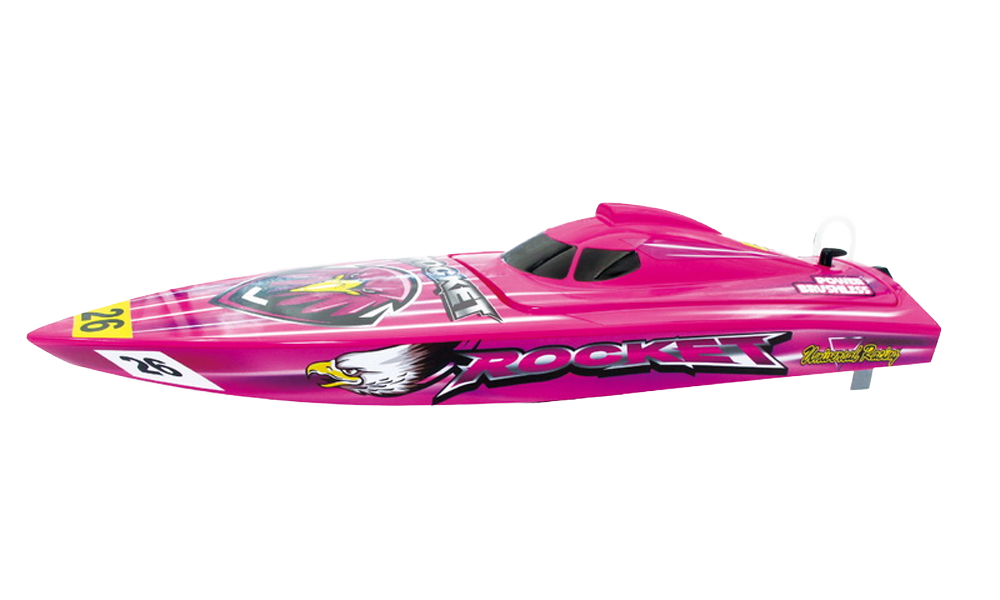
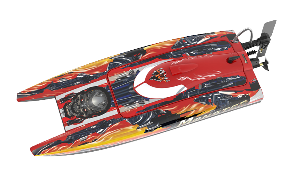
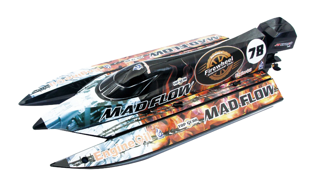
Introduction
These factory-assembled speedboats use water-cooled brushless propulsion and proportional steering and throttle. Complete the preparation below before the first run. Procedures shared by the models are combined; differences are named explicitly.
Specifications
| Parameter | Rocket V2 | Monster | Mad Flow V3 |
|---|---|---|---|
| Manufacturer model | 8651V2 | 8654 | 8653V3 |
| Overall length | 620 mm | 570 mm | 590 mm |
| Beam | 155 mm | 195 mm | 225 mm |
| Speed | >55 km/h | >55 km/h | >55 km/h |
| Parameter | Description |
|---|---|
| Motor | D2842 |
| Water-cooled ESC with BEC | 30 A |
| Rudder servo | 9 g; metal gears |
| Flex shaft | Ø3 mm |
| Propeller | 2-blade plastic propeller – Ø35 mm × 1.4 |
| Recommended drive battery | 3S LiPo 11.1 V 2200 mAh ≥35C; XT60 |
Safety notes
This high-speed model is not a toy. The supplied instructions permit independent use only by persons older than 15. Read the complete manual and test radio range before every run. Keep hands and clothing clear of the propeller; disconnect the drive battery before touching the drive. Metal parts may be sharp and the motor may remain hot after use.
Use this model only in fresh water, in an open area away from swimmers, people, animals and aquatic plants. Do not operate in confined water, rain or thunderstorms. If lightning or thunder occurs, stop operating and disconnect the model safely.
Never enter deep water or a strong current to retrieve a model. If control is lost, first raise the transmitter to try to restore the link. Use a safe recovery method from shore; do not put yourself or anyone else at risk.
Charge outside the model under adult supervision, on a nonflammable surface. Do not leave charging unattended. Use only the correct charger for the battery chemistry and cell count. Never short-circuit, dismantle, crush or burn a battery. Stop using a damaged, swollen or abnormally hot pack. Disconnect it after use and recycle exhausted batteries appropriately.
Contents and required equipment
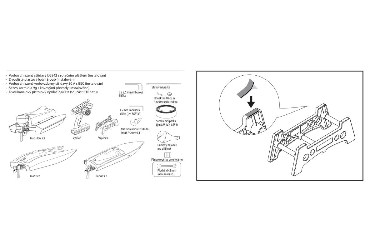
Included: boat with motor, ESC, servo and propeller installed, RTR pistol transmitter, spare propeller, stand with foam supports, receiver balloon and tie, XT60 connector with heat-shrink tubing, and 2mm and 2.5mm hex keys. Mad Flow V3 also includes a 1.5mm hex key; hatch tape is supplied only with Rocket V2 and Monster. Add 2 open-ended 8mm spanners for shaft maintenance, 4 AA transmitter cells, the recommended pack and a suitable LiPo balance charger. Battery and charger are not included.
Main section
Stand and preparation
Join the stand ends with the 3 ABS tubes. Apply the foam pads to the upper supports to protect the hull. Support the boat securely while working, with its battery disconnected.
Use a LiPo balance charger suitable for the specified cell count. If fitting the supplied power connector, match polarity to the ESC: red is positive (+), black is negative (−). Only undertake soldering if competent; insulate each connection and avoid short circuits. Follow the battery and charger instructions.
Optional emergency rudder
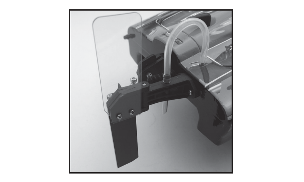
Monster: fit the supplied plastic emergency rudder to the normal rudder with 2 screws, as illustrated. If the boat capsizes, this auxiliary rudder and the propeller acting in air may allow limited control towards shore. This is not a self-righting system and does not justify operation in strong wind or rough water.
Flood chamber and self-righting
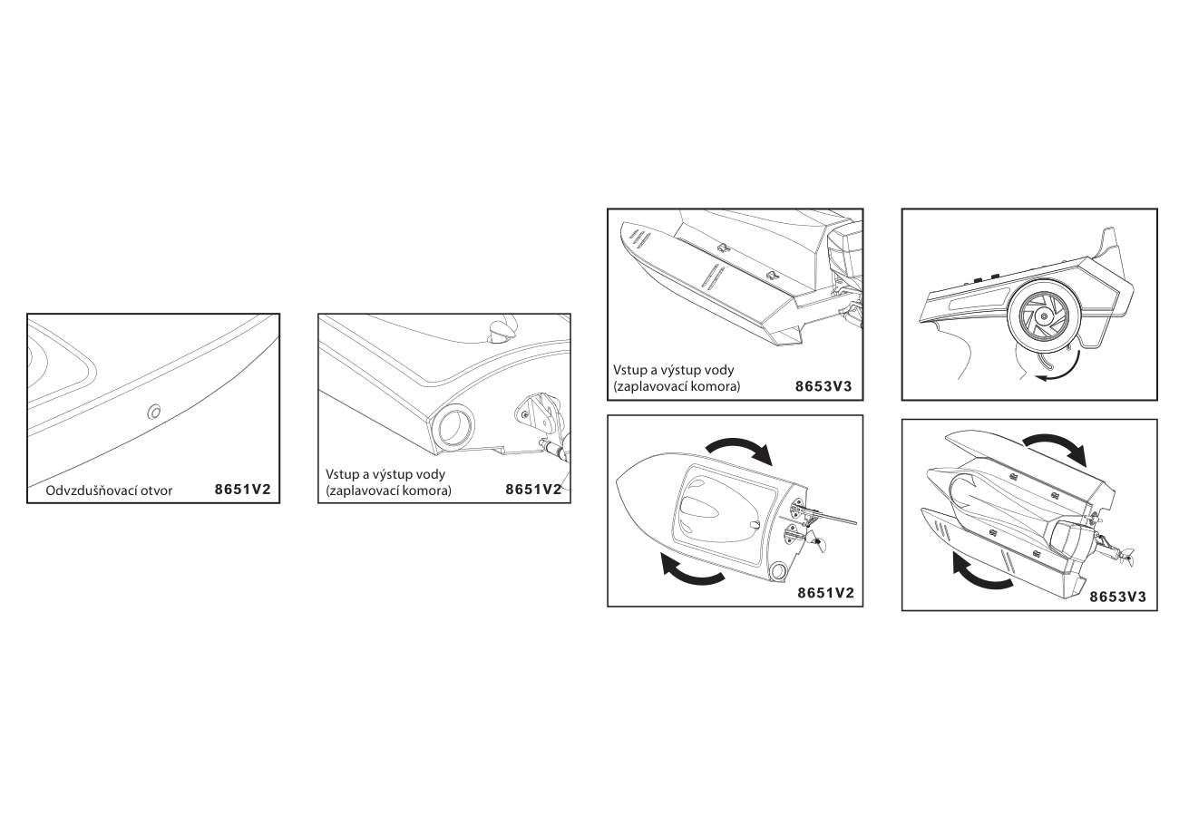
Rocket V2 / Mad Flow V3: the left-hand flood chamber fills when the boat capsizes and shifts its centre of gravity until it rolls upright. Leave the throttle neutral and wait for the chamber to fill. Once upright, accelerate to drain the water through the stern opening. Keep chamber openings and the air vent clear. Recovery is not guaranteed in every condition; use a safe shore-based method if needed.
Transmitter and receiver
- Install 4 AA alkaline cells or charged NiMH cells in the transmitter handle, observing the marked polarity. Switch ON: the red power LED should light. The transmitter is not waterproof; keep it dry.
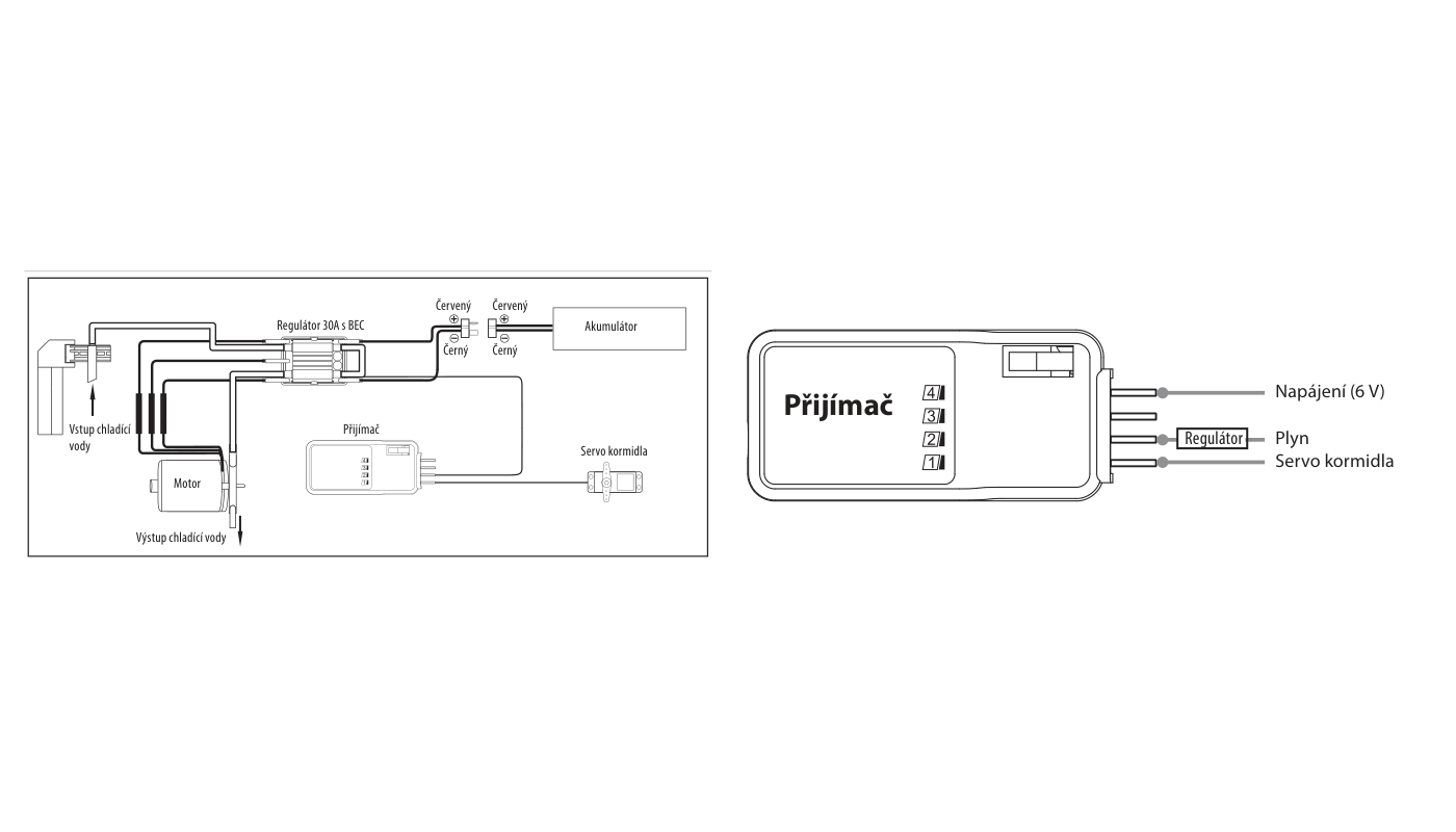
- Check the receiver wiring: steering servo to channel 1, ESC to channel 2. The ESC’s BEC supplies the receiver through its lead; no separate receiver battery is required. Enclose the receiver in the supplied rubber balloon and secure its opening around the leads with the supplied tie or rubber band.
Battery installation and hatch sealing
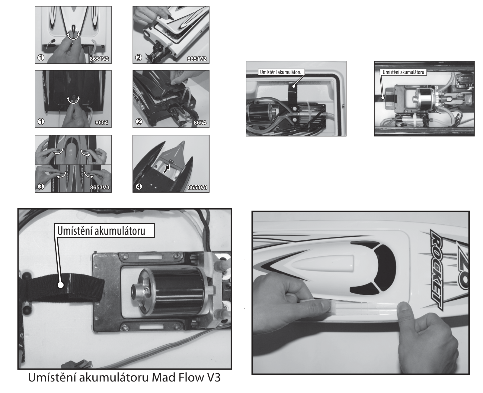
- Rocket V2 and Monster: rotate the hatch latch 90° either way and lift the hatch. Mad Flow V3: release all 4 catches, slide the cover forward, then lift it off.
- Fit the charged 3S pack on the model’s designated tray against its stops and tighten the hook-and-loop strap. The positions differ by hull; follow the corresponding drawing and do not relocate the stops or battery bed.
- Switch on the transmitter at neutral throttle, then connect the drive battery to the ESC. Complete binding and the control checks below before sealing the hatch.
- Inspect the gasket around the entire hatch opening. Fit the cover without trapping wires and engage all catches. After connecting the battery and completing the control checks, seal the complete hatch perimeter with waterproof tape before launching.
Binding and startup
The RTR radio is normally bound at the factory. Bind again only if necessary: a red receiver LED indicates no established link.
- Keep transmitter and receiver within 1 m, with no other active 2.4GHz transmitter within 10 m. Keep the throttle at neutral and switch on the transmitter first.
- Connect the drive battery to the ESC, which powers the receiver. Press the receiver’s BIND button. A steady green LED confirms binding. If green continues flashing, repeat the procedure.
- At normal startup, wait for the ESC’s 3 beeps before checking controls. When stopping, disconnect the boat battery first and switch off the transmitter last. Never leave a drive battery connected when the boat is not in use.
Checking direction, trims and travel
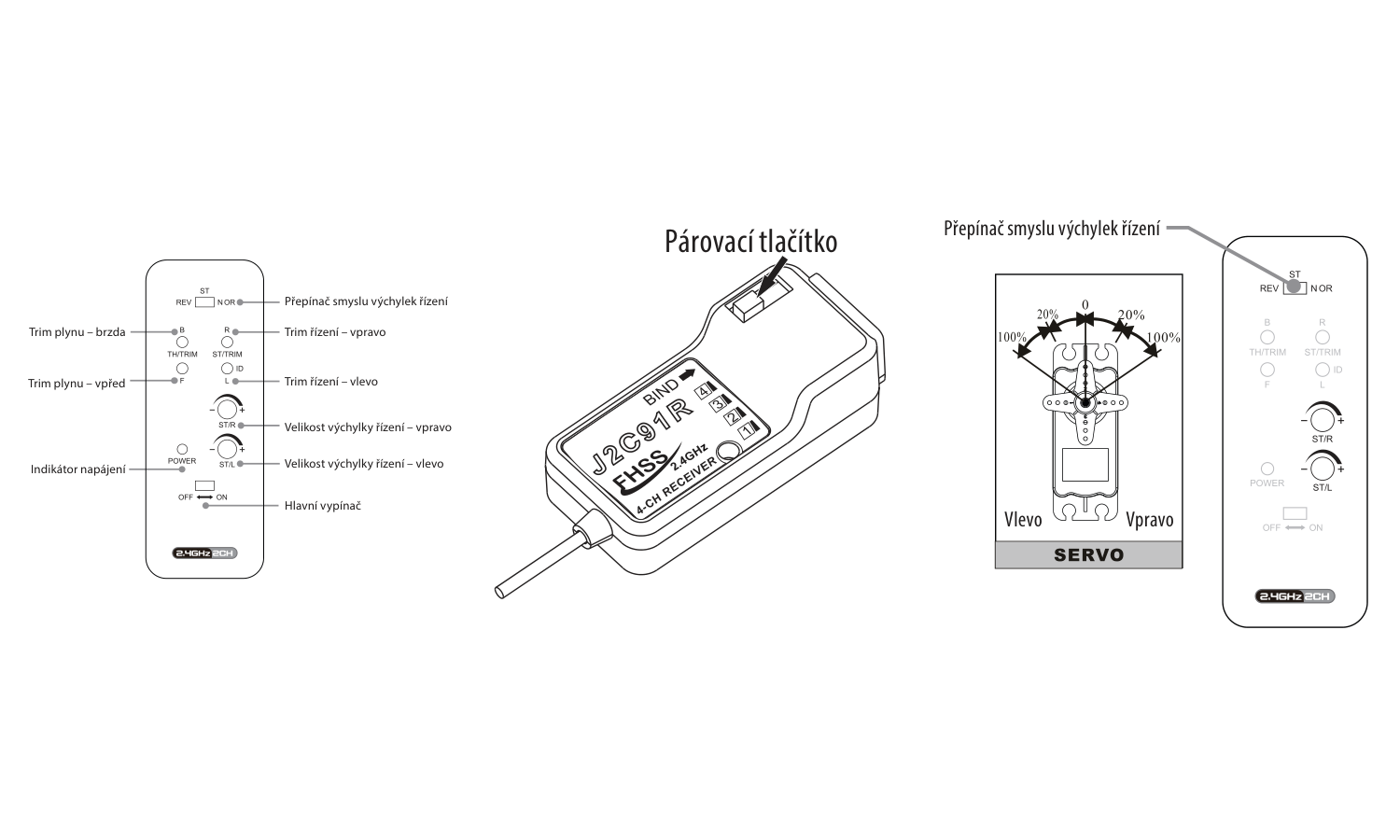
- With the boat supported and the propeller clear, turn the steering wheel right. The rudder’s trailing edge must move right; a left command must move it left. Correct a reversed response with ST REV/NOR, then recheck.
- Use ST/TRIM R/L to centre the rudder. Fine-adjust it on the water so the boat runs straight with the wheel centred.
- Set TH/TRIM B/F so the propeller stops with the trigger released. Briefly pull the trigger to check motor response; keep this dry check short because water cooling is not operating.
- Adjust right and left steering limits separately with ST/R and ST/L. Each knob covers 0–100 %: fully left is 0 %, fully right is 100 %. Start with the factory settings and reduce travel if needed; the servo must not force the linkage against a stop.
Viewed from astern, the propeller must rotate anticlockwise when forward throttle is applied. Keep any dry motor test brief because water cooling is inactive. Check steering and radio range before launching.
ESC specifications and throttle calibration
| Parameter | Description |
|---|---|
| Continuous / peak current | 30 / 40 A (10 s) |
| BEC | 5 V / 2 A |
| ESC input range | 2–3S LiPo |
| Thermal motor cutoff | >110 °C |
| LiPo cutoff per cell | 3.2 V |
Calibration begins with full throttle selected. Remove the propeller before this procedure, secure the boat and keep clear of the drive. Keep the motor connected so the ESC’s tones can be heard.
- Hold full throttle and switch on the transmitter. Connect the drive battery to the ESC.
- After 4 high tones, release the trigger to neutral. After 3 tones, disconnect the battery.
- Reconnect at neutral to check normal startup, then disconnect before refitting the propeller. Repeat calibration only after changing the transmitter, receiver or ESC.
Running and low-voltage protection
Inspect every cooling hose and water inlet before launching. Remove blockages and replace damaged or kinked tubing; loss of cooling can damage the motor and ESC. Start near shore and increase speed progressively. Return as soon as maximum speed begins to fall.
The ESC stops the motor at 3.2 V per LiPo cell. If this happens, return the trigger to neutral to reset, then use only enough power to return slowly to shore. End normal runs before cutoff. Repeated resets can deeply discharge and permanently damage the battery.
If the boat starts bobbing unusually, water may have entered the hull. Return immediately, disconnect the battery, remove the hatch and drain and dry the hull.
After sailing and storage
- Disconnect the drive battery first, then switch the transmitter OFF. Remove the boat battery and the transmitter cells.
- Remove the hatch and gasket, wipe out moisture and leave the hull open in a warm, dry place until completely dry. Store the removable gasket separately in a closed plastic bag away from light to preserve its elasticity.
Allow the motor to cool with the hatch removed for 5–10 min before fitting another charged pack. Continuous operation overheats the motor and increases wear.
Lubricating the flex shaft
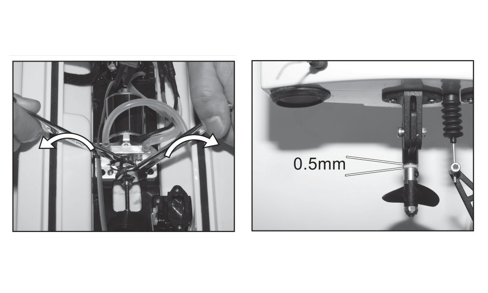
Grease the shaft and plain bearing every 2–3 operating days, or after every operating day if making many runs. Grease reduces wear and helps prevent water entering along the shaft.
- Disconnect all drive batteries before dismantling the drive.
- Use 2 open-ended 8mm spanners to loosen the motor/shaft coupling.
- Withdraw the flex shaft and wipe it with a clean, soft cloth. Apply waterproof marine grease to the shaft and plain bearing; use grease intended for RC boats.
- Dry the inside of the PTFE tube thoroughly, then refit the shaft. Leave a 0.5mm gap between the PTFE washer and metal propeller drive dog before tightening the coupling with the same tools. This clearance is essential.
Appendix
Spare parts
| Part number | Description |
|---|---|
| 865103 | Brushless motor – D2842 |
| 865205 | Water-cooled motor mount |
| 865107 | Rudder pushrod |
| 860103 | Flex shaft set |
| 860104 | Rudder and hinge set |
| 860108 | Plastic stand |
| 860205 | Rear pivoting shaft set, without bearings |
| 860207 | Hatch gasket – 2× |
| 930507 | Bearing set |
| 930511 | 2-blade plastic propeller – Ø35 mm × 1.4 |
| 930512 | Hook-and-loop fastening set |
| 930513 | Silicone antenna cap – 2× |
| 930514 | Silicone cooling hose – 1 m |
| 930515 | Cooling-water outlet |
| 930516 | Shaft coupling |
| 93017 | Rudder pushrod grommet – 2× |
| 880514 | Rudder servo with metal gears – 9 g |
| 865109 | Water-cooled brushless ESC with BEC – 30 A; XT60 |
| 865110 | LiPo 11.1 V 2200 mAh 35C; XT60 |
| 930518 | Transmitter – J2C93; 2.4 GHz |
| 930519 | Receiver – J2C91R; 2.4 GHz |
| 880536 | Rubber plug – 4× |
| 610212 | Balance charger – 2S/3S; EU |
| 865206 | Emergency plastic rudder with 2 screws – Monster |
| 860203 | Flex shaft set – Monster |
| 860206 | Rudder and hinge set – Monster |
| 860304 | Hatch latch set – Mad Flow |
| 860305 | Hatch gasket – Mad Flow; 2× |
| 860309 | Hatch gasket – Mad Flow; 2+2× |
| 860310 | Electronics mounting set – Mad Flow |
| 860311 | Cooling-water inlet set – Mad Flow |
| 860312 | Pushrod with clevis – Mad Flow |
| 860313 | Plastic stand |
| 865302 | Flex shaft set – Mad Flow |
| 865303 | Dummy outboard and rudder set – Mad Flow V3 |
Radio specifications
| Channels: transmitter / receiver | 2 / 4 |
|---|---|
| Frequency / system | 2400–2483.5 MHz / FHSS |
| Maximum transmitter radiated power | <20 dBm |
| Transmitter supply | 4× AA |
| Receiver supply range | 4.8–6.0 V |
Recycling (European Union)
Electrical equipment bearing the crossed-out bin symbol must not be disposed of in normal household waste. Instead, it must be taken to a specialised collection and recycling facility. In EU (European Union) countries, electrical equipment must not be disposed of in normal household waste (WEEE - Waste of Electrical and Electronic Equipment, Directive 2012/19/EU). You can take unwanted equipment to your nearest collection or recycling centre. The equipment will then be disposed of or recycled safely, free of charge. By handing in your unwanted equipment, you can make an important contribution to protecting the environment.
EU Declaration of Conformity
Joysway Hobby International Ltd. hereby declares that the model Rocket V2 / Monster / Mad Flow V3 and other equipment supplied with it are in compliance with Directive 2014/53/EU. The full text of the EU Declaration of Conformity is available at the following website: https://www.kavanrc.com/doc. This 2.4 GHz radio equipment can be used without prior registration or individual approval in all countries of the European Union.
Warranty and post-warranty service
All Joysway products are covered by a 2-year warranty covering all manufacturing defects and faults. When making a claim within the warranty period, please always present a copy of the proof of purchase with the product and provide the service personnel with as detailed and complete information as possible about the defect found, your usage and other information that will facilitate the assessment of the claim and speed up its settlement. Please make your claim at the shop where you purchased the product.
This warranty certificate entitles you to a free warranty repair of the product supplied by KAVAN Europe s.r.o. within a period of 24 months. The warranty does not cover natural wear and tear due to normal use, as this is a product for modelling use, where the individual parts operate under much higher loads than normal toys are subjected to.
The warranty also does not cover any part of the equipment that has been improperly installed, roughly or improperly handled, or damaged in an accident, or any part of the equipment that has been repaired or altered by an unauthorised person (this includes the application of any waterproof sprays/coatings by the user). Like other fine electronics products, do not expose this equipment to high temperatures, low temperatures, moisture, dusty environments, violent mechanical shocks and impacts. Do not leave it in direct sunlight for extended periods of time.
Improper installation includes inadequate mounting, mechanical strain on cables and insufficient cooling.
Please claim warranty repairs from the shop where you purchased the product.
If possible, use the original packaging when returning the product for service. Include a dated description of its use and the fault, together with your full address and telephone number.