Joysway Dragon Flite 95 V3 - Instruction manual
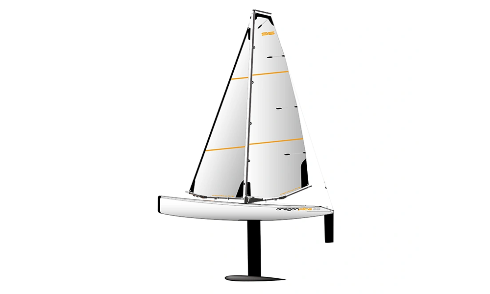
Dragon Flite 95 V3
Introduction
This manual covers the Dragon Flite 95 V3 racing sailboat supplied from early 2025 onwards. Read the complete instructions before assembly and sailing. The rig dimensions provide a basic trim designed for balanced handling; adjust carefully after gaining experience on the water.
Specifications
| Parameter | Description |
|---|---|
| Manufacturer versions | 8811V3 (RTR) / 8811V3A (ARTR) |
| Hull material | Moulded plastic |
| Length | 950 mm |
| Beam | 125 mm |
| Rig / overall height | 1050 / 1470 mm |
| RTR weight without batteries | 2000 g |
| Mainsail / jib / total sail area | 2314 / 1422 / 3736 cm² |
| Sails | Mylar 50 µm |
| RTR radio | Flysky i6 / FS-iA6B, 2.4 GHz |
| Power supply | 4 AA transmitter + 4 AA receiver cells |
| AA cell type in source | Alkaline |
The painted moulded hull carries a digital metal-gear rudder servo and the 2025 DF Racing digital sail winch. The stand supports upright and nearly horizontal storage. DF95 uses a carbon keel; DF65 uses an aluminium keel and carbon mast/boom tubes. Both use a zinc-alloy ballast bulb. RTR includes radio equipment; the manufacturer’s ARTR variant omits transmitter and receiver.
Safety notes
This model is not a toy. Assembly and operation require adult supervision. Never swim after a stranded boat or wade into deep water. Do not enter the water with the transmitter. Arrange a safe recovery method before sailing.
Sail only on still bodies of water, never rivers or tidal waters where a disabled boat could be carried away. Keep clear of swimmers and other users, and keep the boat in sight. Begin in light wind and use conditions suitable for the rig and your experience.
Charge outside the model under adult supervision, on a nonflammable surface. Do not leave charging unattended. Use only the correct charger for the battery chemistry and cell count. Never short-circuit, dismantle, crush or burn a battery. Stop using a damaged, swollen or abnormally hot pack. Disconnect it after use and recycle exhausted batteries appropriately.
Contents and required tools
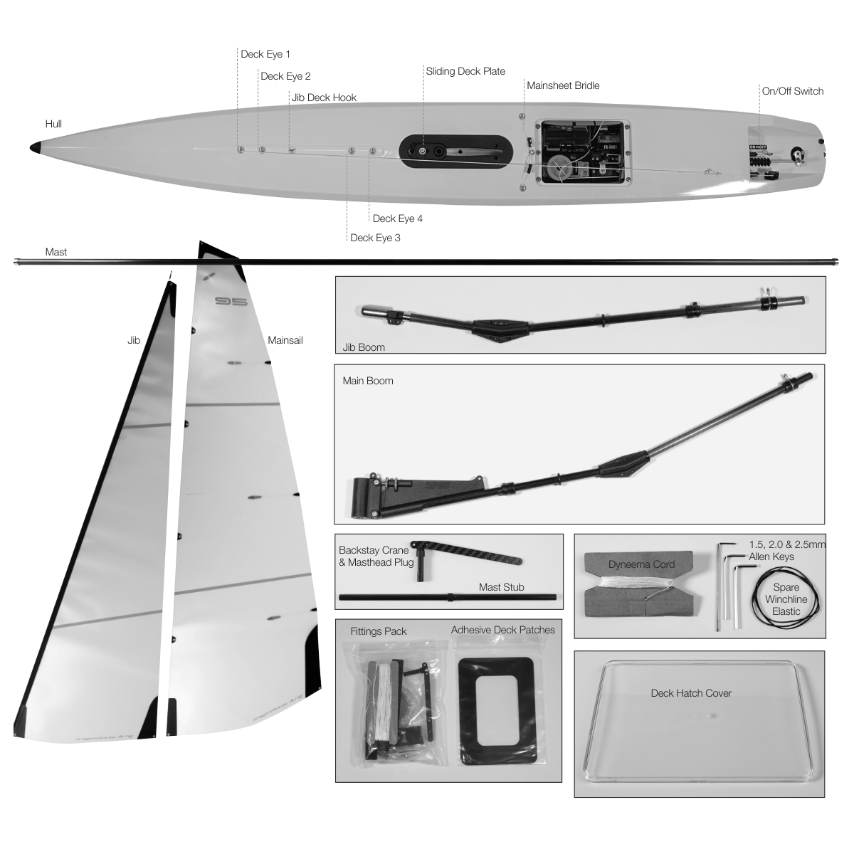
Identify hull and deck fittings, keel and bulb, rudder, mast sections and stub, mainsail and jib, both booms, fittings pack, battery holder, clear hatch and adhesive patches, stand and laydown kit. Check Dyneema, bowsies, metal rings, hooks and masthead fittings before cutting cord. Add thin CA, thin-nosed pliers, a sharp modelling knife and suitable hex keys; the DF95 set lists 1.5mm, 2.0mm and 2.5mm keys. Supply the 8 AA cells and, for ARTR, a compatible radio.
The DF95 contents drawing also identifies spare winch-line elastic. Keep the spare fittings and packing for future maintenance and transport.
Boat and rig terminology
| Term | Meaning |
|---|---|
| Bow / stern | Front / rear of the boat |
| Port / starboard | Left / right when looking forward from the stern |
| Hull / deck | Boat body / its upper surface |
| Keel and ballast | Fin below the hull and its weight, providing lateral resistance and stability |
| Rudder | Movable blade at the stern that steers the boat |
| Mainsail / jib | Sail behind / ahead of the mast |
| Boom / sheet | Spar at the sail foot / line controlling sail angle |
Rigging terms
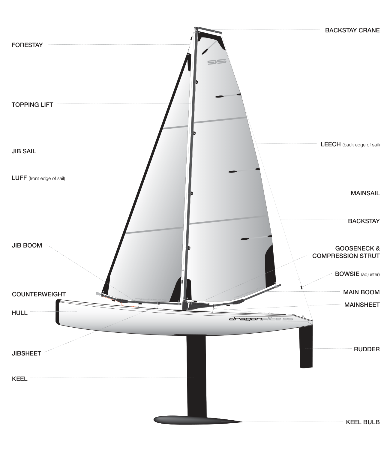
| Term | Description |
|---|---|
| Luff / leech / foot | Front / rear / lower sail edge |
| Head / tack / clew | Top / lower front / lower rear sail corner |
| Forestay / backstay | Rigging supporting the mast forwards / aft |
| Backstay crane | Fitting projecting from the masthead |
| Gooseneck / vang or compression strut | Boom pivot / adjustment controlling mainsail leech twist |
| Cunningham | Downhaul adjusting sail luff tension |
| Jib topping lift | Line supporting the jib boom end and controlling jib leech twist |
| Bowsie / mainsheet bridle | Line-length adjuster / deck bridle carrying the mainsheet ring |
Main section
Assembling the stand
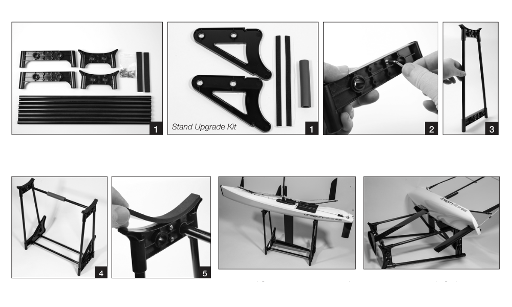
- Identify the moulded joints, tubes, laydown upgrade parts, 12 nuts and bolts, and EVA pads. Bolt the plastic components together.
- Build the leg sections; all leg and cross-brace tubes are equal in length on DF95. Fit the laydown parts onto the cross-braces, then join these to the legs.
- Attach EVA pads to all hull contact surfaces, including the laydown parts. Use the upright position for rigging and indoor storage; outdoors, lay the stand on its side and secure the hull nearly horizontally for greater stability.
Keel and ballast bulb
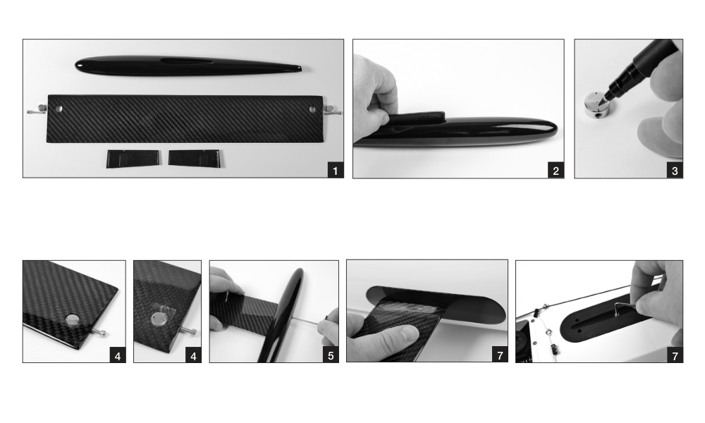
- Insert the plastic shoes into the bulb slot. Mark the threaded-hole centres on each fixing disc to help alignment. Place the lower disc in the keel hole, align it and temporarily fit the hex-head bolt to check engagement. Hold the disc with thin tape, then remove the bolt.
- Slide the keel between the plastic shoes in the bulb and secure it with the bolt. Prepare the upper fixing disc in the same way. Insert the keel into the hull and secure the upper bolt. The mainsheet bridle plate will be fitted under this bolt during sheet installation.
Fitting the rudder
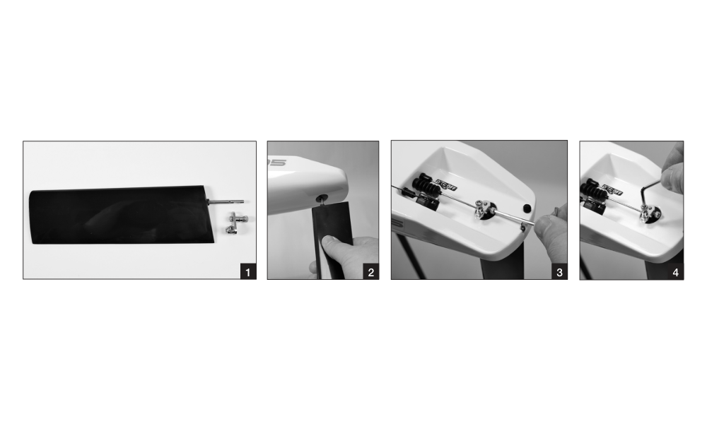
- Insert the rudder shaft fully into the hull. Fit the metal rudder arm over the shaft and the steering rod through the arm’s upper hole. Push the blade fully upwards and the arm downwards, then tighten the shaft grub screw against the shaft’s flat.
- Align the blade with the hull centreline and tighten the upper grub screw onto the steering rod. Recheck and adjust this screw after powering the radio with steering stick and trim centred.
Preparing cord and bowsies
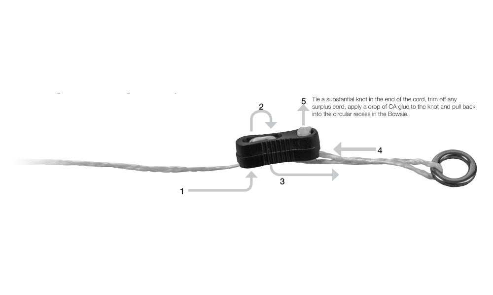
- Before cutting Dyneema, apply a few drops of thin cyanoacrylate at the cut point. Cut diagonally through the hardened section to make a sharp end that threads easily. After tying and trimming each knot, secure it with a drop of glue.
- Thread each bowsie up through its first hole, down through the next, around the attachment eye or ring, and back up through the remaining hole. Tie a substantial stopper knot, trim and glue it, then seat it in the circular recess. Keep glue out of sliding fittings and bearings.
Rigging the mainsail
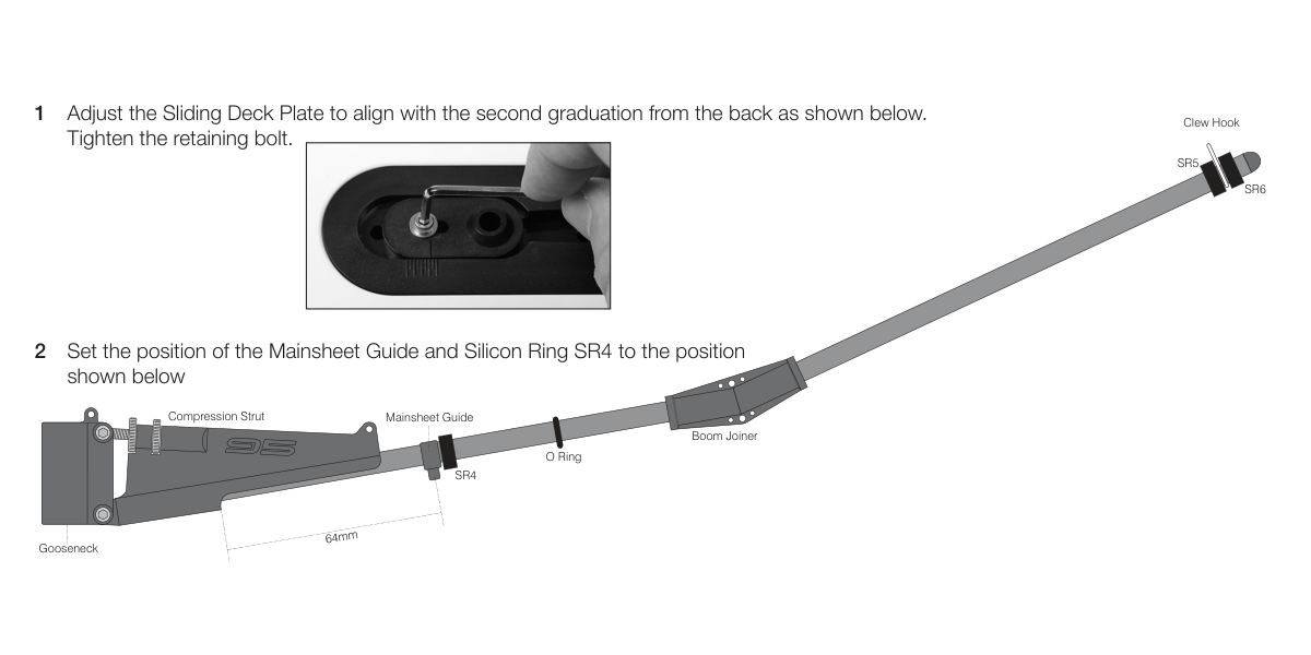
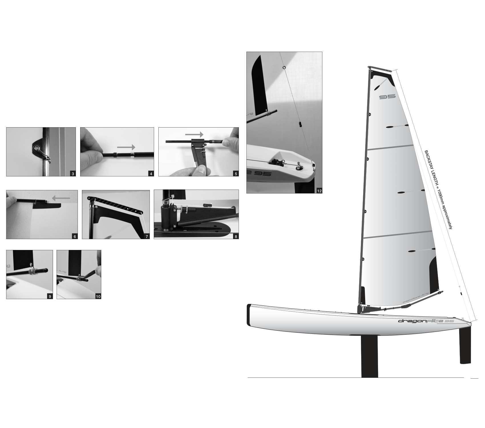
- Set the sliding deck plate at the second graduation from the rear and tighten its bolt. Position the mainsheet guide and silicone ring SR4 at the 64mm dimension in the drawing; this is measured from the rear edge of the lower gooseneck arm, not from the mast axis.
- Fit wire luff rings to all 6 luff eyelets. Insert the mast stub with the bevelled collar edge downwards. Slide the boom assembly onto the stub from below, then slide the luff rings down the mast starting with the lowest ring.
- Fit the crane and masthead plug. Use a 250mm cord to tie the sail head to the crane, level with the top of the mast’s metal reinforcement ring. Use only a single strand so the sail head can rotate freely with the booms out at 80°.
- Make the Cunningham from 300 mm of cord: tie to the upper gooseneck eye, lead through the lower luff eyelet and back through the gooseneck eye, then aft along the boom through a bowsie, the compression-strut eye and back through the bowsie.
- Attach the clew to its hook. Close the open end slightly with thin-nosed pliers to retain the sail; a flat screwdriver can reopen it for removal. Tie 900 mm of cord to the crane’s rear hole and a supplied 6mm metal ring to the lower end. Step the mast into the deck socket.
- For the lower backstay, cut 500 mm, make an end loop, then pass the free end through a bowsie, the upper section’s metal ring and back through the bowsie. Hook the loop to the transom hook, apply light tension and tie off with the bowsie near the middle. Set the complete backstay to approximately 1090 mm as drawn.
- Tension the mainsail leech lightly with the compression strut, then back it off one turn to allow slight twist. Apply very light luff tension with the Cunningham. Adjust SR5/SR6 and the clew hook for approximately 25 mm between boom-tube centre and sail foot at its midpoint.
Jib boom and sail
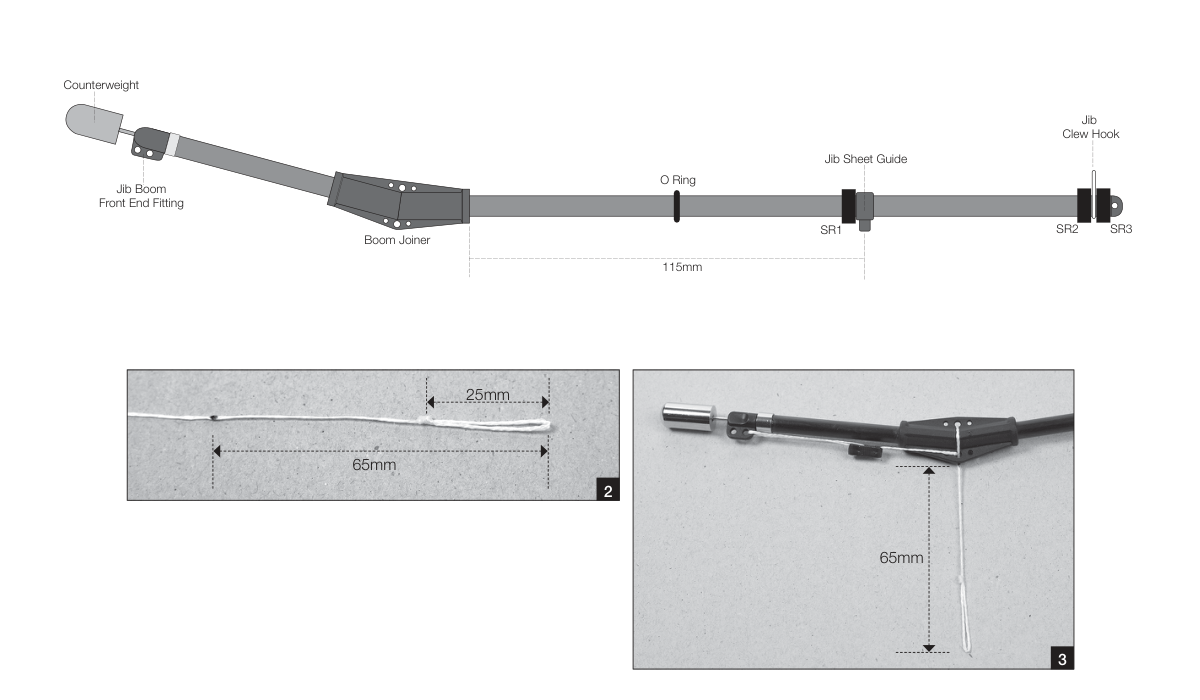
- Set the jibsheet guide and SR1 at 115 mm from the rear of the boom joiner, as drawn. Cut 450 mm for the hook-down, tie a 25mm loop, glue its knot and mark 65 mm from the loop end.
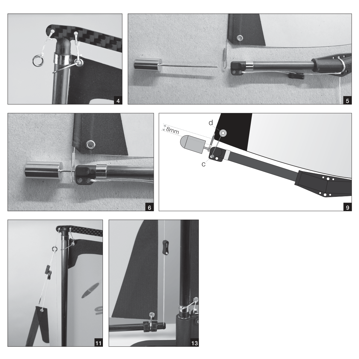
- Pass the free end up through the lower central joiner eye, through the upper central eye, down through the lower eye again, forwards beneath the boom, through a bowsie, the rear eye of the front fitting and back through the bowsie. Align the mark with the joiner’s lower edge; position the bowsie halfway to the front fitting and tie off.
- Use 200 mm of cord to tie a 6mm metal ring 15 mm below the crane’s front hole. Remove the jib counterweight, tighten it on its shaft and secure the thread with thin CA. Check that the jib luff slides freely on the wire forestay; gently free any sticking point without creasing the sail.
- Pass the counterweight shaft through the lower forestay loop and into the front fitting, leaving about 5 mm exposed. Fit the clew hook and close it slightly with pliers. Make the jib Cunningham from 150 mm: tie to the lower front fitting hole, pass through the tack eyelet and tie back, leaving about 8 mm between boom top and sail bottom.
- Slacken the hook-down, pass its loop through deck eye 1, then aft through deck eye 2 and over the jib deck hook. Tighten its bowsie to bring the boom as close to the deck as possible.
- For the upper forestay use 200 mm: tie to the wire’s top loop, pass through a bowsie, the hanging metal ring and back. Tie with the bowsie about 10 mm below the ring, then tension until luff wrinkles appear. Use another 200 mm from the sail’s head eyelet through a separate bowsie, the same ring and back; tension just enough to remove those wrinkles.
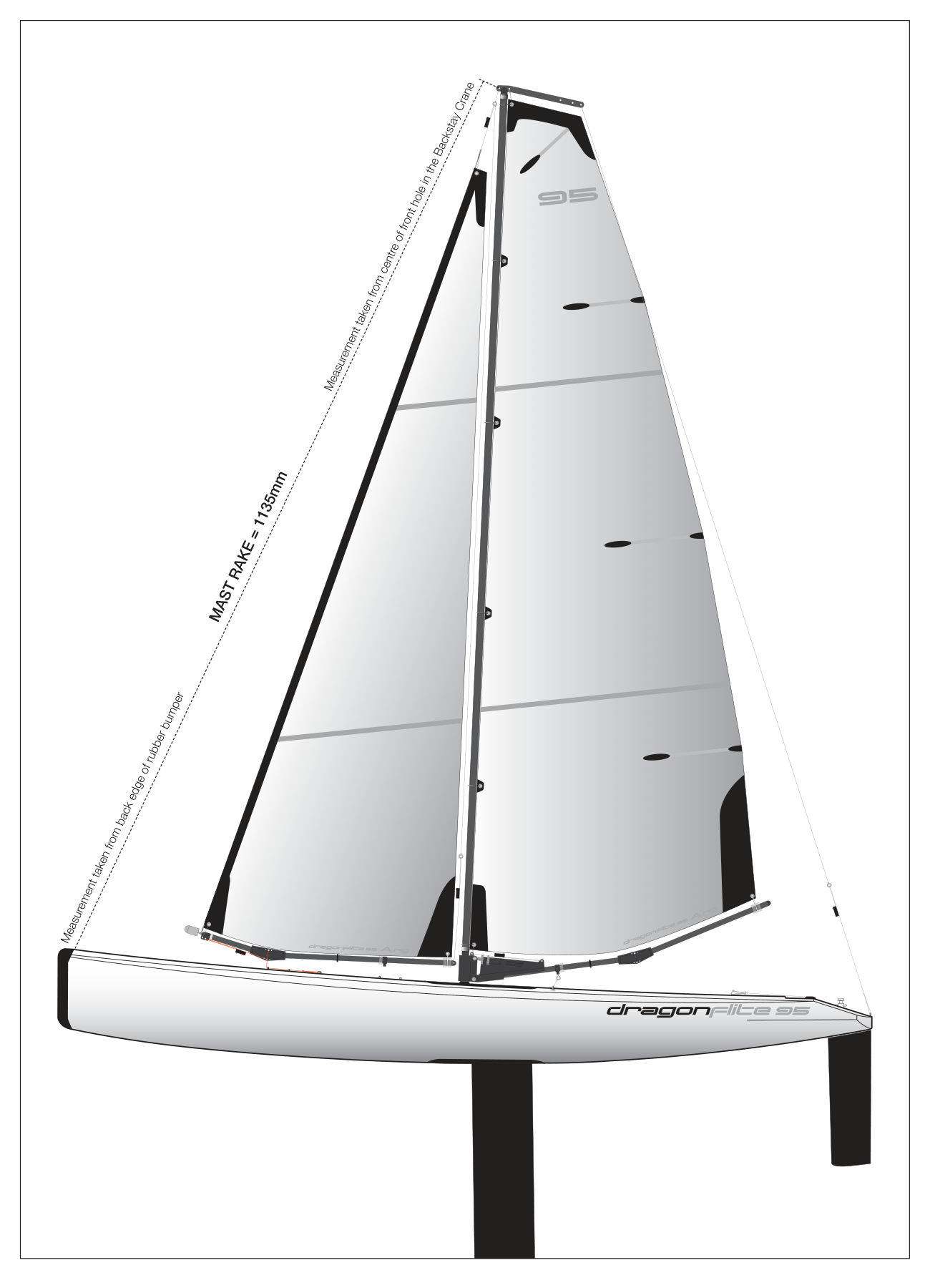
- Set mast rake by adjusting the forestay and jib luff adjusters: measure 1135 mm from the back edge of the rubber bow bumper to the centre of the crane’s front hole. The forestay and backstay must be firmly tensioned to stabilise the rig.
- Make the topping lift from 1150 mm: tie to the forestay metal ring, lead down through a bowsie just above the boom end, through the end eye and back through the bowsie. Leave slight leech slack. Adjust SR2/SR3 and the clew hook for about 25 mm of jib-foot depth, measured from boom centre at the foot midpoint.
For later rig installation: step the mast, attach and tighten the jib hook-down, then attach and tension the backstay. Reverse this order to remove the rig. Leave forestay adjustment unchanged to retain the established trim.
Radio and winch setup
RTR includes the factory-bound Flysky i6 and FS-iA6B. Read the supplied radio manual. With your own radio, use its instructions for reversing, travel, binding and failsafe. Check range and signal-loss behaviour before launch.
| Rudder servo | CH1 |
|---|---|
| Sail winch | CH3 |
| Battery through switch | CH5 |
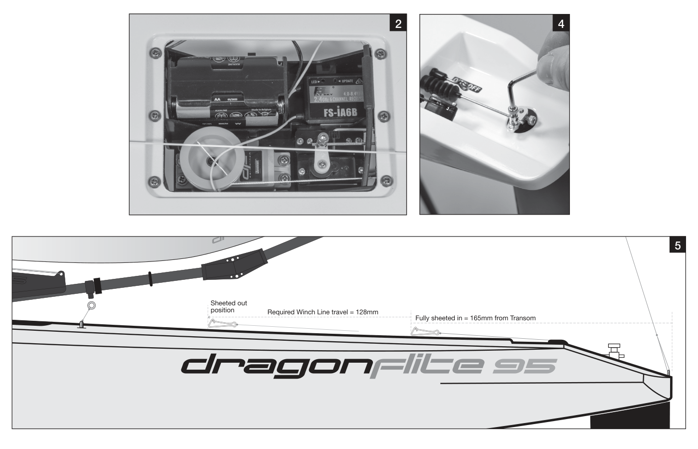
- Fit 4 AA cells to the receiver holder and secure it on the tray with the silicone band. Connect it to the switch’s spare lead. Fit 4 AA cells to the transmitter, observing polarity. Centre sticks and trims; turn the transmitter on first, then push the boat’s wire switch arm forwards to switch on.
- Viewed from the stern, right steering must turn the rudder right. Moving the sail stick down must move the winch-line clip fully aft, sheeting in. Correct reversed directions using the radio manual. With rudder stick and trim centred, align the blade with the keel by loosening and resetting the rudder arm’s upper grub screw.
- Set sail trim to centre and pull the sail stick fully down. The fully sheeted-in clip end should be 165 mm from the transom. If necessary, remove the winch-drum screw, rotate the drum to set that position and refasten it. Set 128 mm total winch-line travel between fully in and fully out, using individual radio end-point settings where available. Mark both positions on deck; travel is more important than their absolute location.
Installing the sheets
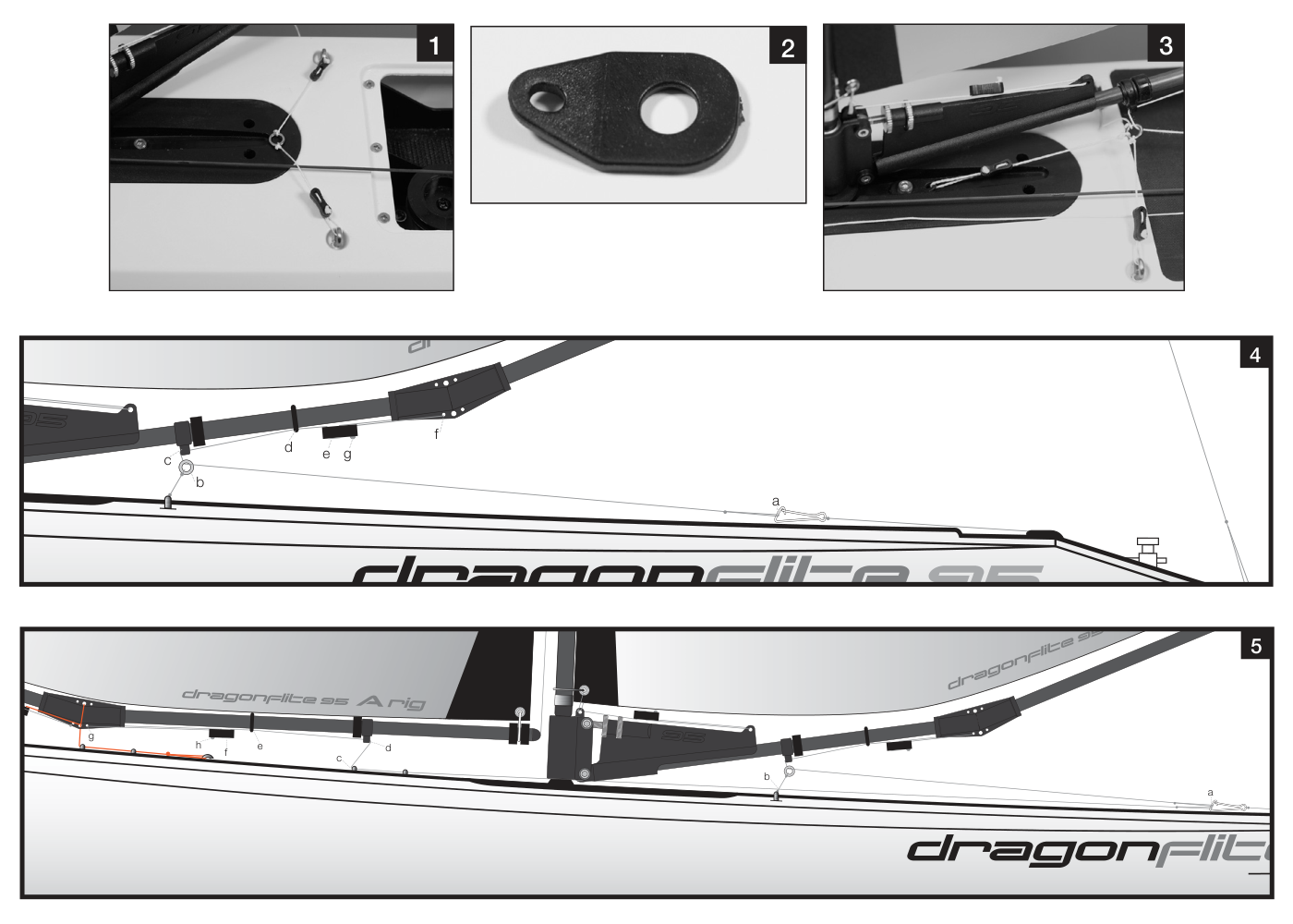
- Adjust the mainsheet bridle bowsies so its ring is centred across the hull for equal port/starboard sheeting. Tie 180 mm of cord to the ring, pass through a bowsie, the small hole of the keel-bolt plate and back. Fit the plate under the top keel bolt and retighten. Adjust the ring directly below the boom’s mainsheet guide and tie off. Pull the winch fully to the sheeted-in position and leave it there until both sheets are installed. The lettered routes below correspond to the source drawing.
- Mainsheet, 600 mm: make an end loop and attach to winch clip (a) → forward through bridle ring (b) → up through boom guide (c) → aft through O-ring (d) → first holes of bowsie (e) → first boom-joiner hole (f) → forward through final bowsie hole (g). Hold the boom on the centreline and tie with the bowsie midway between (c) and (f).
- Jibsheet, 850 mm: loop on clip (a) → forward under bridle (b) → deck eye 3 (c) → up through jib guide (d) → forward under boom through O-ring (e) → bowsie (f) → rear joiner hole (g) → final bowsie hole (h). Hold the boom end over the gunwale and tie with the bowsie midway between (d) and (g).
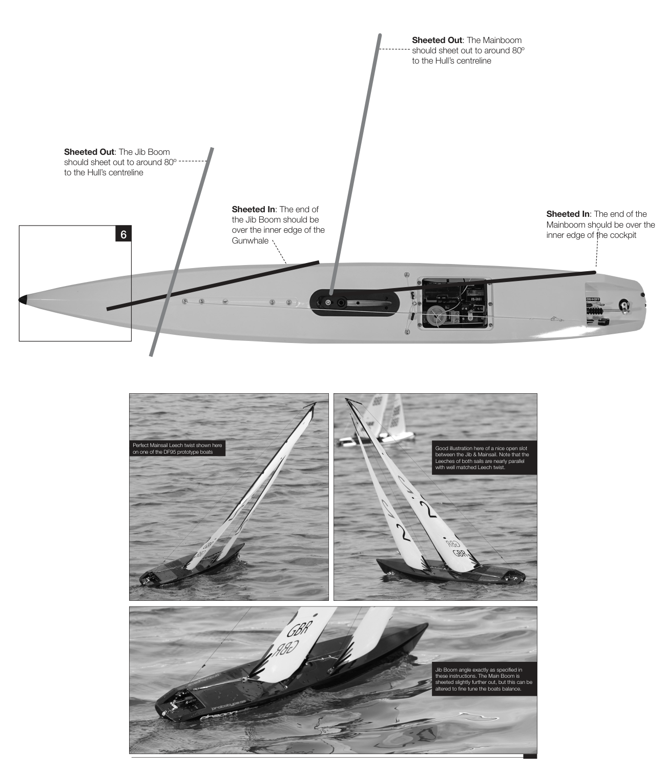
With sheets in, set the main boom end over the cockpit’s inner edge and the jib boom end at the gunwale’s inner edge. With sheets out, the main boom should be about 80° and jib boom about 80° to the centreline. Adjust mainsail twist with the strut/vang and jib twist with the topping lift. Aim for a clear slot and smoothly opening, nearly parallel leeches; excessive twist loses power.
Sealing the hatch and launching
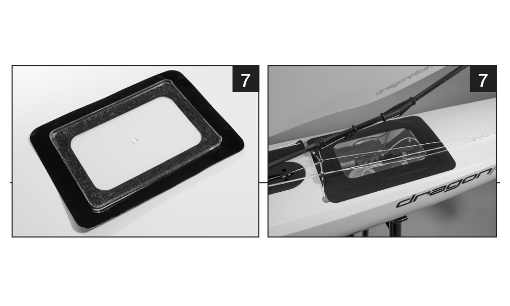
- Lay an adhesive deck patch face down on a smooth firm surface and remove its backing. Centre the clear hatch upside down on the adhesive. Turn over, position in the opening and press the patch onto the deck without creases to form a continuous waterproof seal.
Check battery condition, range, rudder direction, free sheeting and hatch seals before launching. Make smooth, gradual rudder and sail movements. Hard rudder at a tack acts as a brake; minimise corrections downwind to retain speed.
Sailing
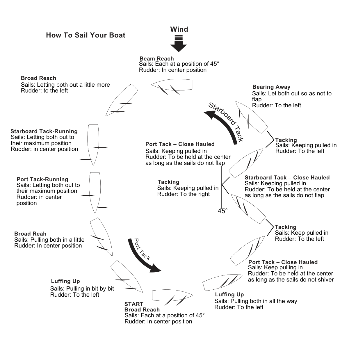
A sailing boat has no throttle to propel it: adjust the rudder and sheets as wind direction, gusts and water movement change. The boat cannot sail directly into the wind. Sail towards an upwind destination by alternating close-hauled courses on opposite tacks.
| Course or manoeuvre | Sail and rudder setting |
|---|---|
| Beam reach | Start with both sails about 45° out and the rudder centred. Adjust for a steady course. |
| Close-hauled | Pull both sails in. Hold the rudder near centre once on course; avoid pointing so high that the sails flap. |
| Tacking | Keep the sails in and steer the bow through the wind to the other tack. Centre the rudder when the turn is complete. |
| Bearing away / broad reach | Turn away from the wind and ease both sails progressively, keeping them filled rather than flapping. |
| Running | Ease both sails fully and hold the required course with small rudder movements. |
| Gybing / heading up | For a gybe, steer the stern through the wind and control the sails as they change sides. When heading back towards the wind, pull the sheets in progressively. Left/right rudder commands depend on the boat’s present course. |
After sailing
- Switch the receiver OFF first, then switch off the transmitter. Disconnect the receiver batteries.
- Open the deck hatch and let the interior dry completely. Trapped moisture can corrode and damage the radio equipment. Store the boat supported on its stand with the rig protected from damage.
Rig maintenance
- After every saltwater outing, rinse the whole hull and rig, especially the upper and lower gooseneck bearings, with clean fresh water. Lubricate these bearings regularly with bearing lubricant.
- Never store water or condensation inside the hull: corrosion, including blackened wiring, can cause electrical failure. Dyneema may shrink; check rig dimensions and tension regularly.
- Do not leave sails flapping while the boat is on its stand. Lay it on a soft surface with the rig downwind of the hull. Store rigs carefully in a rigid box or a sufficiently stiff rig bag.
Appendix
Spare parts
| Reference | Version | Description | Pack quantity |
|---|---|---|---|
| 881113 | DF95 | Masthead pack – A | 1 |
| 881114 | DF95 | Masthead pack – B | 1 |
| 881115 | DF95 | Masthead pack – C / D | 1 |
| 881122 | DF95 V1–V3 | Mainsail luff rings | 10 |
| 881124 | DF95 | Water-sealing tape | 2 |
| 881126 | DF95 | Bow bumper | 2 |
| 881127 | DF95 | Sheeting pulley block | 2 |
| 881129 | DF95 | Rudder | 1 |
| 881130 | DF95 V1–V3 | Carbon keel with bolts | 1 |
| 881131 | DF95 V1–V3 | Keel bolts | 4 |
| 881132 | DF95 | Ballast with plastic shoe fitting | 1 |
| 881133 | DF95 | Plastic shoe | 1 |
| 881134 | DF95 | Rudder pushrod | 1 |
| 881135 | DF95 | Switch connector and operating rod | 1 |
| 881137 | DF95 | Jib boom front fitting | 4 |
| 881138 | DF95 | Boom joiner | 4 |
| 881140 | DF95 | Hull decals | 1 |
| 881157 | DF95 V1–V3 | Bearings | 4 |
| 881167 | DF95 V1–V3 | Hull – White | 1 |
| 881168 | DF95 V1–V3 | Hull – Black | 1 |
| 881169 | DF95 V1–V3 | Hull – Blue | 1 |
| 881170 | DF95 V1–V3 | Hull – Purple | 1 |
| 881171 | DF95 V1–V3 | Hull – Orange | 1 |
| 881172 | DF95 V1–V3 | Hull – Yellow | 1 |
| 881173 | DF95 V1–V3 | Hull – Dark blue | 1 |
| 881174 | DF95 V1–V3 | Hull – Red | 1 |
| 881175 | DF95 V1–V3 | Hull – Green | 1 |
| 881194 | DF95 V1–V3 | Hull – Silver | 1 |
| 881195 | DF95 V1–V3 | Hull – Grey | 1 |
| 8811002 | DF95 V1–V3 | Hull – Metallic fluorescent orange | 1 |
| 8811003 | DF95 V1–V3 | Hull – Metallic fluorescent pink | 1 |
| 8811004 | DF95 V1–V3 | Hull – Metallic fluorescent yellow | 1 |
| 881180 | DF95 | Boom band eye | 10 |
| 881189 | DF95 | Receiver and battery-holder O-rings, 2 large + 2 small | 1 |
| 881190 | DF95 | Rudder-post insert – 2020 | 1 |
| 881192 | DF95 | Mast protection rings | 5 |
| 881193 | DF95 | Jib-boom protection rings | 5 |
| 881196 | DF95 | Gooseneck | 2 |
| 881197 | DF95 | Compression strut | 1 |
| 881198 | DF95 | Standard stand with laydown upgrade | 1 |
| 881199 | DF95 | Winch drum – 25 mm | 1 |
| 8811001 | DF95 | Rig bag – Brown | 1 |
| 8811006 | DF95 | Boat case – Blue | 1 |
| 8811007 | DF95 V1–V3 | Transparent hatch | 2 |
| 8811008 | DF95 V1–V3 | Deck cloth patch | 4 |
| 8811009 | DF95 V1–V3 | Keelbox and mast fitting | 1 |
| 8811010 | DF95 V1–V3 | Mast socket tube | 1 |
| 8811011 | DF95 V1–V3 | Mainsheet bridle keel-bolt plate | 2 |
| 8811012 | DF95 V1–V3 | Jib boom rear plugs ×5 + main boom rear plugs ×5 | 1 |
| 8811013 | DF95 V1–V3 | Servo tray with screws | 1 |
| 8811014 | DF95 V1–V3 | Mylar sail set, packed in round tube – A / 50 µm | 1 |
| 8811015 | DF95 V1–V3 | Mylar sail set, packed in round tube – B / 75 µm | 1 |
| 8811016 | DF95 V1–V3 | Mylar sail set, packed in round tube – C / 75 µm | 1 |
| 8811017 | DF95 V1–V3 | Mylar sail set, packed in round tube – D / 75 µm | 1 |
| 8811018 | DF95 V1–V3 | Mast set – A | 1 |
| 8811019 | DF95 V1–V3 | Mast set – B | 1 |
| 8811020 | DF95 V1–V3 | Mast set – C | 1 |
| 8811021 | DF95 V1–V3 | Mast set – D | 1 |
| 8811022 | DF95 V1–V3 | Jib boom set – A | 1 |
| 8811023 | DF95 V1–V3 | Jib boom set – B | 1 |
| 8811024 | DF95 V1–V3 | Jib boom set – C | 1 |
| 8811025 | DF95 V1–V3 | Jib boom set – D | 1 |
| 8811026 | DF95 V1–V3 | Main boom set – A | 1 |
| 8811027 | DF95 V1–V3 | Main boom set – B | 1 |
| 8811028 | DF95 V1–V3 | Main boom set – C | 1 |
| 8811029 | DF95 V1–V3 | Main boom set – D | 1 |
| 8811030 | DF95 V1–V3 | Complete rig without sails – A | 1 |
| 8811031 | DF95 V1–V3 | Complete rig without sails – B | 1 |
| 8811032 | DF95 V1–V3 | Complete rig without sails – C | 1 |
| 8811033 | DF95 V1–V3 | Complete rig without sails – D | 1 |
| 881301 | DF95 V1–V3 | Sliding deck plate with screw and washer | 2 |
| 880519 | DF65/95 | Winch-line rubber cap | 2 |
| 880536 | DF65/95 | Rubber bung | 4 |
| 880552 | DF65/95 | Receiver battery holder | 1 |
| 881504 | DF65/95 | Digital metal-gear rudder servo and new arm | 1 |
| 881526 | DF65/95 | Metal rings – 2020 | 10 |
| 881551 | DF65/95 | Backstay hook and screw | 5 |
| 881558 | DF65/95 | Receiver LiFePO₄ battery – 6.4 V / 700 mAh | 1 |
| 881559 | DF65/95 | USB charger for receiver LiFePO₄ battery – 6.4 V / 700 mAh | 1 |
| 881563 | DF65/95 | Knurled wheels ×2 and bolt ×1 | 1 |
| 881569 | DF65/95 | Stand laydown upgrade | 1 |
| 881576 | Flysky i6 + iA6B | Radio set | 1 |
| 881580 | Flysky FS-iA6B | Receiver | 1 |
| 881581 | DF65/95 | Elasticated sheeting cord – 1 m | 1 |
| 881582 | DF65/95 | Aluminium rudder arm and clevis | 1 |
| 881588 | DF65/95 | 2025 digital DF Racing winch with 16mm and 25mm drums | 1 |
| 881210 | DF65/95 | Bowsies | 10 |
| 881227 | DF65/95 | Waterproof bellows | 4 |
| 881228 | DF65/95 | Cord attachment clips – 2020 | 10 |
| 83016 | DF65/95 | Clevises | 2 |
| 881203 | DF95 | Metal sail clew hooks | 10 |
| 881204 | DF95 | Dyneema cord – Ø0.6 mm / 10 m | 1 |
| 881209 | DF95 | Jib counterweight with shaft | 4 |
| 881211 | DF95 | Silicone tube ×18 and O-rings ×4 | 1 |
| 881226 | DF95 V1 | Sail winch servo | 1 |
Recycling (European Union)
Electrical equipment bearing the crossed-out bin symbol must not be disposed of in normal household waste. Instead, it must be taken to a specialised collection and recycling facility. In EU (European Union) countries, electrical equipment must not be disposed of in normal household waste (WEEE - Waste of Electrical and Electronic Equipment, Directive 2012/19/EU). You can take unwanted equipment to your nearest collection or recycling centre. The equipment will then be disposed of or recycled safely, free of charge. By handing in your unwanted equipment, you can make an important contribution to protecting the environment.
EU Declaration of Conformity
Joysway Hobby International Ltd. hereby declares that the model Dragonflite 95 V3 and other equipment supplied with it are in compliance with Directive 2014/53/EU. The full text of the EU Declaration of Conformity is available at the following website: https://www.kavanrc.com/doc. This 2.4 GHz radio equipment can be used without prior registration or individual approval in all countries of the European Union.
Warranty and post-warranty service
All Joysway products are covered by a 2-year warranty covering all manufacturing defects and faults. When making a claim within the warranty period, please always present a copy of the proof of purchase with the product and provide the service personnel with as detailed and complete information as possible about the defect found, your usage and other information that will facilitate the assessment of the claim and speed up its settlement. Please make your claim at the shop where you purchased the product.
This warranty certificate entitles you to a free warranty repair of the product supplied by KAVAN Europe s.r.o. within a period of 24 months. The warranty does not cover natural wear and tear due to normal use, as this is a product for modelling use, where the individual parts operate under much higher loads than normal toys are subjected to.
The warranty also does not cover any part of the equipment that has been improperly installed, roughly or improperly handled, or damaged in an accident, or any part of the equipment that has been repaired or altered by an unauthorised person (this includes the application of any waterproof sprays/coatings by the user). Like other fine electronics products, do not expose this equipment to high temperatures, low temperatures, moisture, dusty environments, violent mechanical shocks and impacts. Do not leave it in direct sunlight for extended periods of time.
Improper installation includes inadequate mounting, mechanical strain on cables and insufficient cooling.
Please claim warranty repairs from the shop where you purchased the product.
If possible, use the original packaging when returning the product for service. Include a dated description of its use and the fault, together with your full address and telephone number.