Joysway Orion V2 - Instruction manual
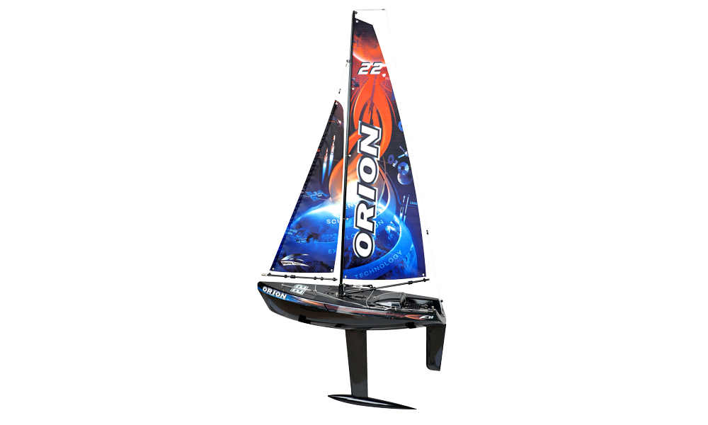
Orion V2
Introduction
Orion V2 is a 465mm ready-to-run sailing yacht supplied with its radio, sail servo and rudder servo installed. Assemble the stand, ballast keel, rudder and rig before sailing.
Safety notes
This model is not a toy. Never swim after a stranded boat or wade into deep water. Do not enter the water with the transmitter. Arrange a safe recovery method before sailing.
Sail only on still water in suitable light winds. Do not use rivers, streams, strong currents or heavy winds. Keep the boat in sight, away from swimmers and other users. For the first outings, choose a wind direction that will carry a disabled boat back towards your shore.
The supplied manual permits independent assembly and operation by persons older than 14. Read the full procedure before starting. Keep small rigging parts and tools away from younger children.
Specifications
| Parameter | Orion V2 |
|---|---|
| Length / beam | 465 / 150 mm |
| Mast height / overall height | 637 / 920 mm |
| RTR weight | 950 g |
| Mainsail / jib area | 7.39 / 3.78 dm² |
| Total sail area | 11.17 dm² |
| Hull | Painted moulded plastic with decals |
| Radio channels: transmitter / receiver | 2 / 4 |
| Frequency / system | 2400–2483.5 MHz / FHSS |
| Maximum radiated power | <20 dBm |
| Receiver supply | 4.8–6.0 V |
| Batteries, not included | 4× AA for transmitter + 4× AA for receiver |
Set contents and tools
The set contains the hull with servos and battery holder, transmitter, mainsail and jib, mast sections and fittings, main and jib booms, rudder and arm, keel and ballast, 2 M4 nuts, S-hooks, Dyneema line, bowsies, deck patches and stand. Supplied hex keys are 1.5 mm and 2.5 mm. Add a flat-blade screwdriver and 8 AA alkaline cells or suitable AA rechargeable cells: 4 for each unit.
Use fresh alkaline cells or fully charged NiMH cells of the same type within each holder. The older parts list calls the radio set J2C03, while the specification table calls its transmitter J2C02. Identify the supplied hardware before ordering radio spares; the binding procedure below is for the receiver with a BIND button described in this PDF.
Boat and rig terminology
| Term | Meaning |
|---|---|
| Bow / stern | Front / rear of the boat |
| Port / starboard | Left / right when looking forward from the stern |
| Hull / deck | Boat body / its upper surface |
| Keel and ballast | Fin below the hull and its weight, providing lateral resistance and stability |
| Rudder | Movable blade at the stern that steers the boat |
| Mainsail / jib | Sail behind / ahead of the mast |
| Boom / sheet | Spar at the sail foot / line controlling sail angle |
Main section
Assembling the stand
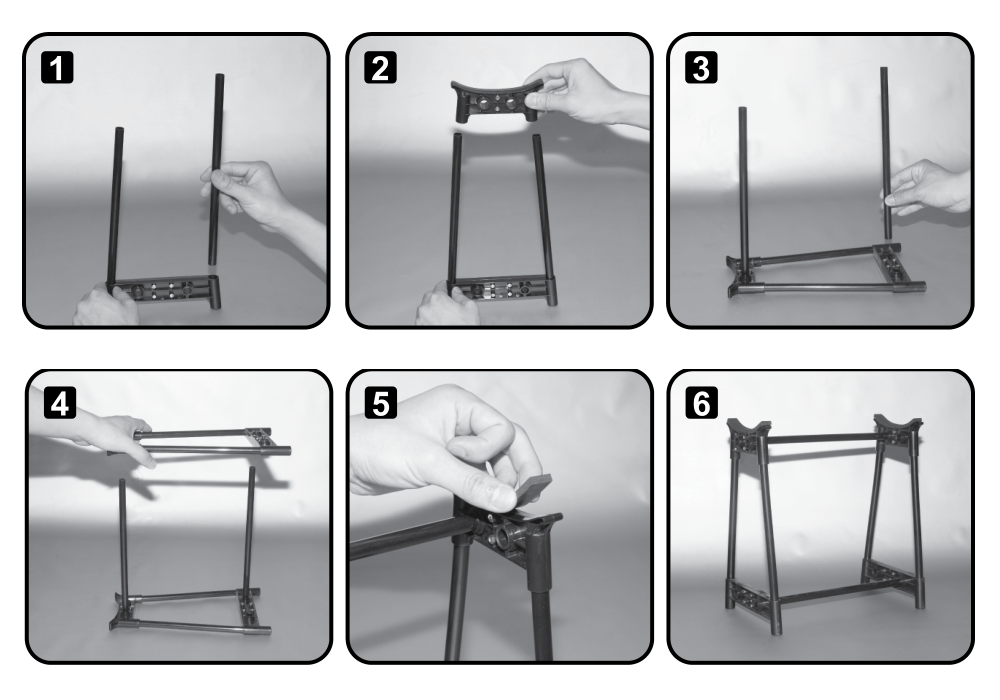
- Insert the 2 ABS tubes into the lower stand-end piece, then fit the upper piece over their free ends.
- Fit the longitudinal tubes into the upper and lower pieces. Assemble the second end in the same way and fit it onto those tubes.
- Apply the foam pads to both upper supports before placing the hull on the stand.
Keel, ballast and rudder
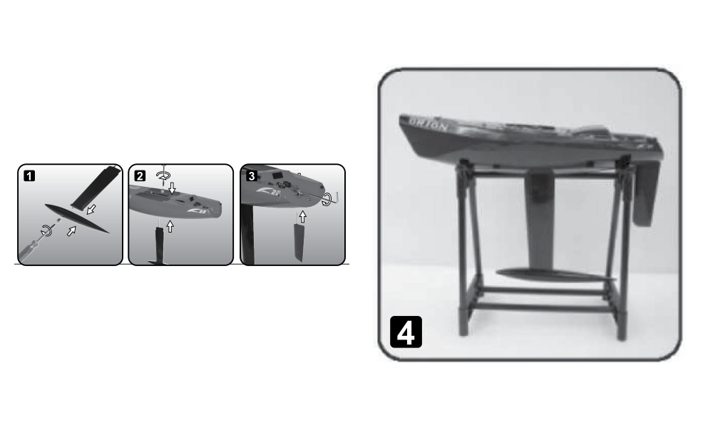
- Fasten the ballast to the keel with an M4 nut. Fit the assembled keel to the hull and secure it with the other M4 nut.
- Insert the rudder shaft from below, with the blade oriented as in the drawing. Fit its control arm using the 2.5mm hex key. The rudder must turn freely with no more than 0.5 mm vertical play.
- Final rudder centring is done later with the radio powered and the rudder stick and trim centred.
Rigging the mainsail and mast
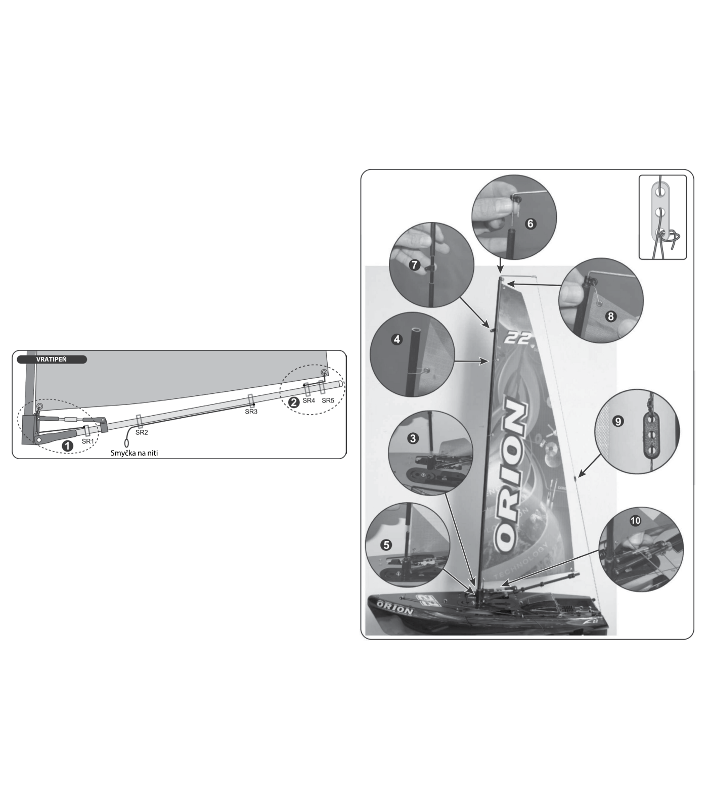
- Lead the line attached to main-boom ring SR1 through the lower gooseneck eye from rear to front, then through the upper eye, through the mainsail tack eye and back to the upper gooseneck eye, where it is tied. Leave about 10 mm between the boom and sail foot at the tack.
- Tie the line from SR4, passing through SR5, to the mainsail clew eye. Leave about 15 mm between the boom and sail foot there. Sliding SR5 adjusts the sail’s foot shape.
- Slide the gooseneck body onto the longer end of the mast stub, then insert the assembly into the hull’s mast socket.
- Slide the mainsail luff rings onto the long mast section. Fit that mast section onto the mast stub.
- Insert the metal masthead crane into the plastic masthead, then into the short mast section. Fit the mast joiner with its forestay eye into the bottom of this section, then join it to the long mast section.
- Hang the mainsail head eye on the S-hook at the masthead.
- Cut approximately 1000 mm of Dyneema for the backstay. Tie it to the metal masthead eye. Pass the free end through the first 2 bowsie holes in the illustrated order, through the stern S-hook, then tie it in the third bowsie hole. Tension the backstay with the bowsie.
- Slide SR1 to tension the mainsail luff and SR5 to set its foot shape. Adjust the gooseneck kicking strap with the 1.5mm hex key to control leech tension. Do not pull the leech completely tight; it must retain some freedom.
Rigging the jib
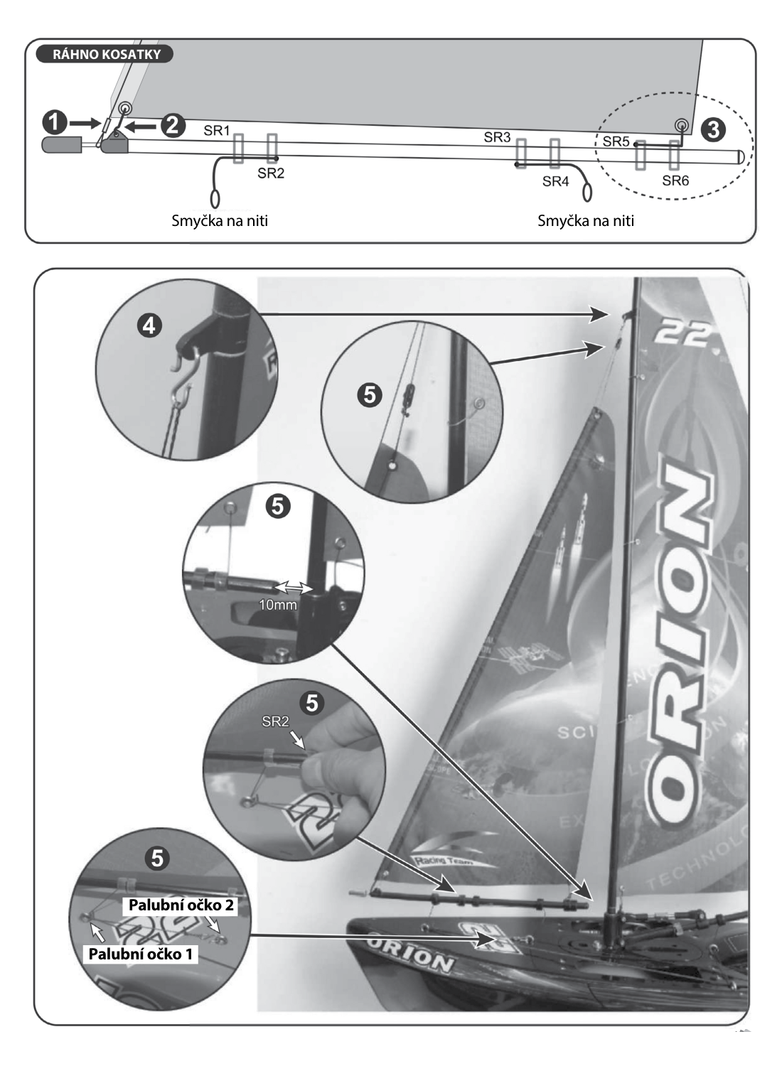
- Slip the loop at the bottom of the forestay onto the jib-boom counterweight shaft. Attach the jib tack eye to the S-hook at the front of the jib boom.
- Tie the line attached at jib ring SR5 and passing through SR6 to the jib clew eye, leaving about 10 mm between boom and sail foot. Sliding SR6 changes the sail shape.
- Use a supplied S-hook to attach the top of the forestay to the mast eye.
- Find the line attached to jib ring SR2 and passing through SR1. Pass its free loop through deck eye 1 and use an S-hook to secure the loop to deck eye 2. This provides a removable jib attachment.
- Adjust the forestay bowsie and SR2 to tension the jib, retaining the 10mm foot-to-boom spacing specified in the text. Set the jib foot shape with SR6.
Installing batteries and switching on
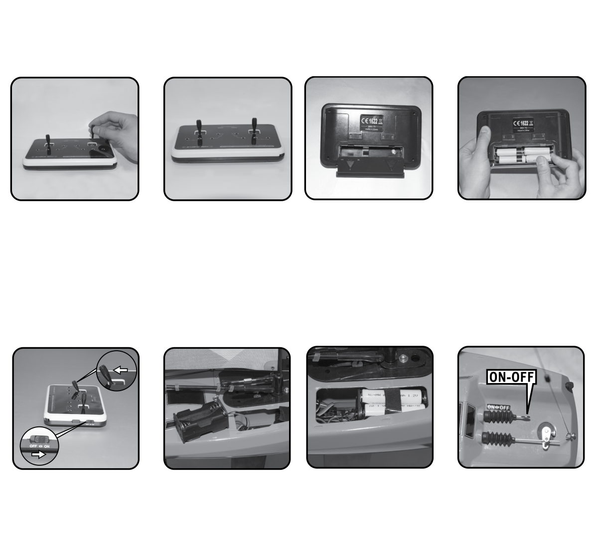
- Fit the transmitter stick extensions. With POWER at OFF, remove the rear cover and install 4 AA cells with correct polarity. Refit the cover.
- Move the left sail stick fully down and switch the transmitter ON. Its green indicator should light. If it remains dark, check cell polarity and contacts. A flashing green light with beeping indicates weak transmitter batteries; replace or recharge them.
- With the receiver off, remove its holder from the hull and fit 4 AA cells correctly. Return the holder to the hull and secure it with the hook-and-loop strap.
- With the transmitter on and sail stick still fully down, push the receiver switch rod to ON. A green receiver LED indicates a bound, ready receiver. Red means no transmitter link or no binding; follow the binding procedure below.
The source radio activates control only with the left sail stick fully down at startup. Always switch on the transmitter first and switch off the receiver first.
Binding if required
- Keep transmitter and receiver within 1 m, with no other active 2.4GHz transmitter within 10 m. Put the sail stick fully down and switch on the transmitter.
- Check the 4 receiver cells and holder, then push the receiver switch rod to ON. Press the receiver’s BIND button.
- The green LED flashes, then remains steadily lit after successful binding. Confirm both controls respond. If it keeps flashing, repeat the procedure.
Connecting the sheets
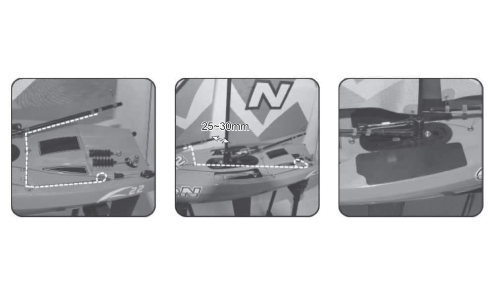
- With the radio on, move the left stick fully down to pull in the sail-control line. Pull the switch rod out to switch off the receiver, then switch off the transmitter before tying the sheets.
- Lead the main-boom looped line, attached at SR3 and passing through SR2, through deck eyes 3 and 4. Attach it to the clip at the end of the sail-control line. Adjust SR2 and SR3 so the main boom is pulled in on the hull centreline.
- Lead the jib-boom looped line, attached at SR3 and passing through SR4, through deck eye 2 to the same clip. Adjust SR3 and SR4 so the jib boom is pulled in with its rear end 25–30 mm from the mast.
- Seal the deck openings with the 2 adhesive patches. Keep their adhesive surfaces clean when removing them for battery changes. Replace worn patches that no longer seal reliably; the listed replacement is 880321.
Checks before sailing
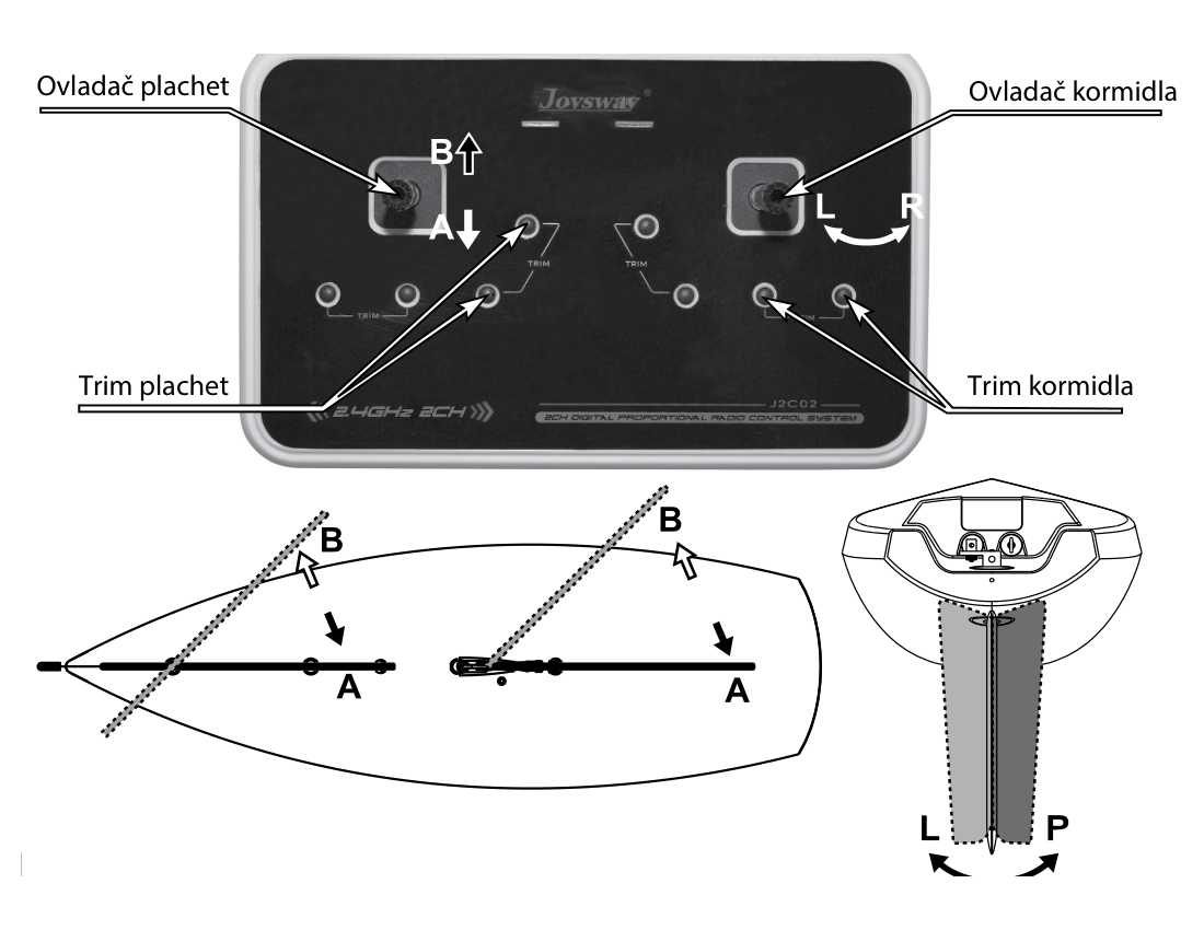
- Switch on in the correct order. With the sail stick down at A, both sails must be pulled in; with it up at B, both must ease out. Adjust sail neutral with the sail trim buttons and check that lines run freely without overloading the servo.
- Check that left rudder-stick input moves the rudder left and right input moves it right. Centre the rudder with its trim. Recheck keel fastenings, rig tension, battery security and watertight deck patches.
Sailing
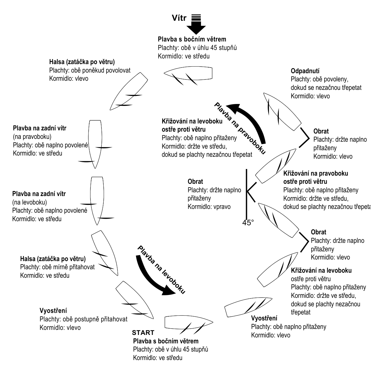
A sailing boat has no throttle to propel it: adjust the rudder and sheets as wind direction, gusts and water movement change. The boat cannot sail directly into the wind. Sail towards an upwind destination by alternating close-hauled courses on opposite tacks.
| Course or manoeuvre | Sail and rudder setting |
|---|---|
| Beam reach | Start with both sails about 45° out and the rudder centred. Adjust for a steady course. |
| Close-hauled | Pull both sails in. Hold the rudder near centre once on course; avoid pointing so high that the sails flap. |
| Tacking | Keep the sails in and steer the bow through the wind to the other tack. Centre the rudder when the turn is complete. |
| Bearing away / broad reach | Turn away from the wind and ease both sails progressively, keeping them filled rather than flapping. |
| Running | Ease both sails fully and hold the required course with small rudder movements. |
| Gybing / heading up | For a gybe, steer the stern through the wind and control the sails as they change sides. When heading back towards the wind, pull the sheets in progressively. Left/right rudder commands depend on the boat’s present course. |
Points of sail and the example sailing course relative to the wind. (Fig. 8)
Begin with the sheets slightly eased and practise a figure-eight course using the rudder. Place the long axis of the figure eight across the wind. Once this is consistent, add active sail trimming and practise returning upwind before sailing farther away.
After sailing
- Switch the receiver OFF first, then switch off the transmitter. Disconnect the receiver batteries.
- Open the deck hatch and let the interior dry completely. Trapped moisture can corrode and damage the radio equipment. Store the boat supported on its stand with the rig protected from damage.
Appendix
Spare parts
| Part no. | Description |
|---|---|
| 880304 | ABS keel with screws |
| 880305 | Standard ballast, 360 g |
| 880306 | Standard mast set |
| 880307 | Jib-boom set with fittings |
| 880308 | Main-boom set with fittings |
| 880311 | Sail servo and arm |
| 880312 | 9g rudder servo |
| 880313 | Plastic servo tray |
| 880314 | Pushrod and rubber seal |
| 880315 | Switch, rod and seal set |
| 880316 | Rudder |
| 880318 | J2C03 transmitter and receiver set |
| 880319 | Plastic stand |
| 880321 | Servo-hatch patches, 4 pcs |
| 880322 | Orion V2 hull without decals |
| 880323 | Orion V2 decals |
| 880324 | Orion V2 standard sail set |
| 880505 | Mast-mount set |
| 880510 | Sheet pulley set |
| 880511 | Sheet elastic, 1 m |
| 880516 | Receiver |
| 880519 | Sheet fairleads, 2 pcs |
| 880529 | Masthead set |
| 880532 | Deck eyes, 10 pcs |
| 880533 | Sail attachment rings, 10 pcs |
| 880535 | Aluminium rudder-arm set |
| 880536 | Rubber plugs, 4 pcs |
| 880537 | Jib-boom counterweights, 4 pcs |
| 881507 | White Dyneema line, 5 m |
| 881538 | Black silicone tube pieces, 20 pcs |
| 881210 | Bowsies, 10 pcs |
Recycling (European Union)
Electrical equipment bearing the crossed-out bin symbol must not be disposed of in normal household waste. Instead, it must be taken to a specialised collection and recycling facility. In EU (European Union) countries, electrical equipment must not be disposed of in normal household waste (WEEE - Waste of Electrical and Electronic Equipment, Directive 2012/19/EU). You can take unwanted equipment to your nearest collection or recycling centre. The equipment will then be disposed of or recycled safely, free of charge. By handing in your unwanted equipment, you can make an important contribution to protecting the environment.
EU Declaration of Conformity
Joysway Hobby International Ltd. hereby declares that the model Orion V2 and other equipment supplied with it are in compliance with Directive 2014/53/EU. The full text of the EU Declaration of Conformity is available at the following website: https://www.kavanrc.com/doc. This 2.4 GHz radio equipment can be used without prior registration or individual approval in all countries of the European Union.
Warranty and post-warranty service
All Joysway products are covered by a 2-year warranty covering all manufacturing defects and faults. When making a claim within the warranty period, please always present a copy of the proof of purchase with the product and provide the service personnel with as detailed and complete information as possible about the defect found, your usage and other information that will facilitate the assessment of the claim and speed up its settlement. Please make your claim at the shop where you purchased the product.
This warranty certificate entitles you to a free warranty repair of the product supplied by KAVAN Europe s.r.o. within a period of 24 months. The warranty does not cover natural wear and tear due to normal use, as this is a product for modelling use, where the individual parts operate under much higher loads than normal toys are subjected to.
The warranty also does not cover any part of the equipment that has been improperly installed, roughly or improperly handled, or damaged in an accident, or any part of the equipment that has been repaired or altered by an unauthorised person (this includes the application of any waterproof sprays/coatings by the user). Like other fine electronics products, do not expose this equipment to high temperatures, low temperatures, moisture, dusty environments, violent mechanical shocks and impacts. Do not leave it in direct sunlight for extended periods of time.
Improper installation includes inadequate mounting, mechanical strain on cables and insufficient cooling.
Please claim warranty repairs from the shop where you purchased the product.
If possible, use the original packaging when returning the product for service. Include a dated description of its use and the fault, together with your full address and telephone number.