Joysway Alpha - Instruction manual
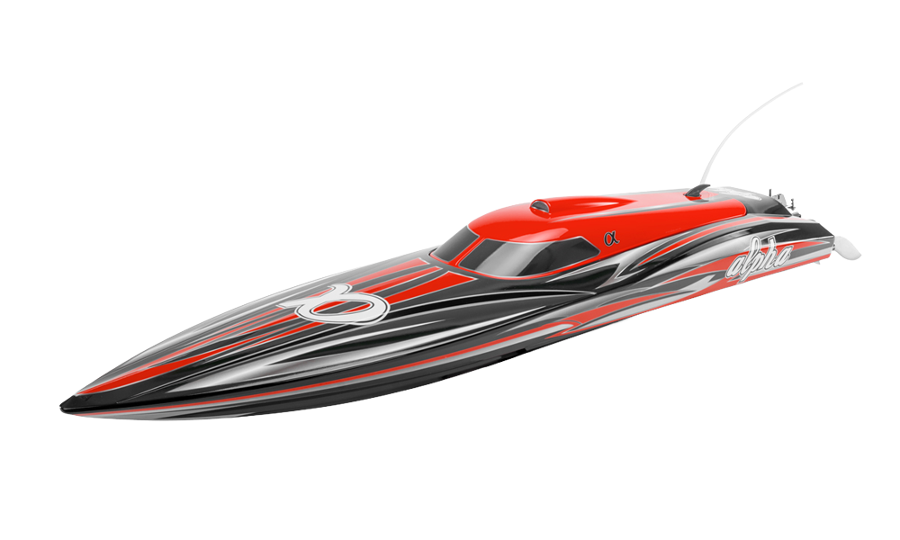
Alpha – red
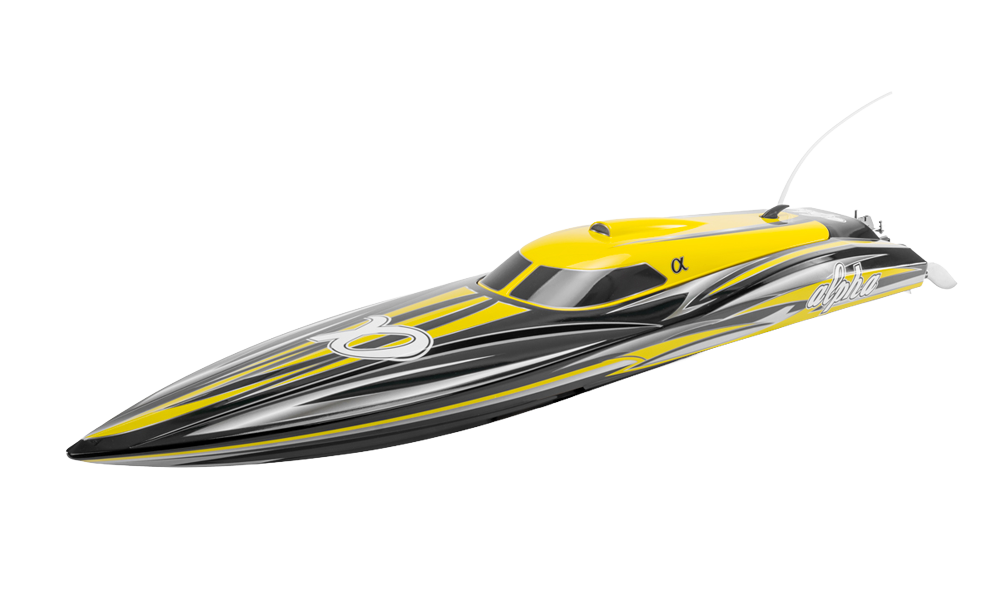
Alpha – yellow
Introduction
Alpha is a high-performance brushless deep-V boat capable of more than 80 km/h in the specified configuration. Read all instructions before assembly, charging or running. This document preserves the equipment and procedures of this version
Specifications
| Hull / total length | 950 / 1060 mm |
|---|---|
| Beam | 260 mm |
| Motor | Water-cooled BL4260 |
| ESC | Water-cooled 90 A with BEC |
| Steering servo torque | 9 kg·cm |
| Shaft | Direct-drive flex Ø5 mm |
Battery and propeller combinations
| Total cells | Two matching packs in series | Metal propeller | Approximate speed |
|---|---|---|---|
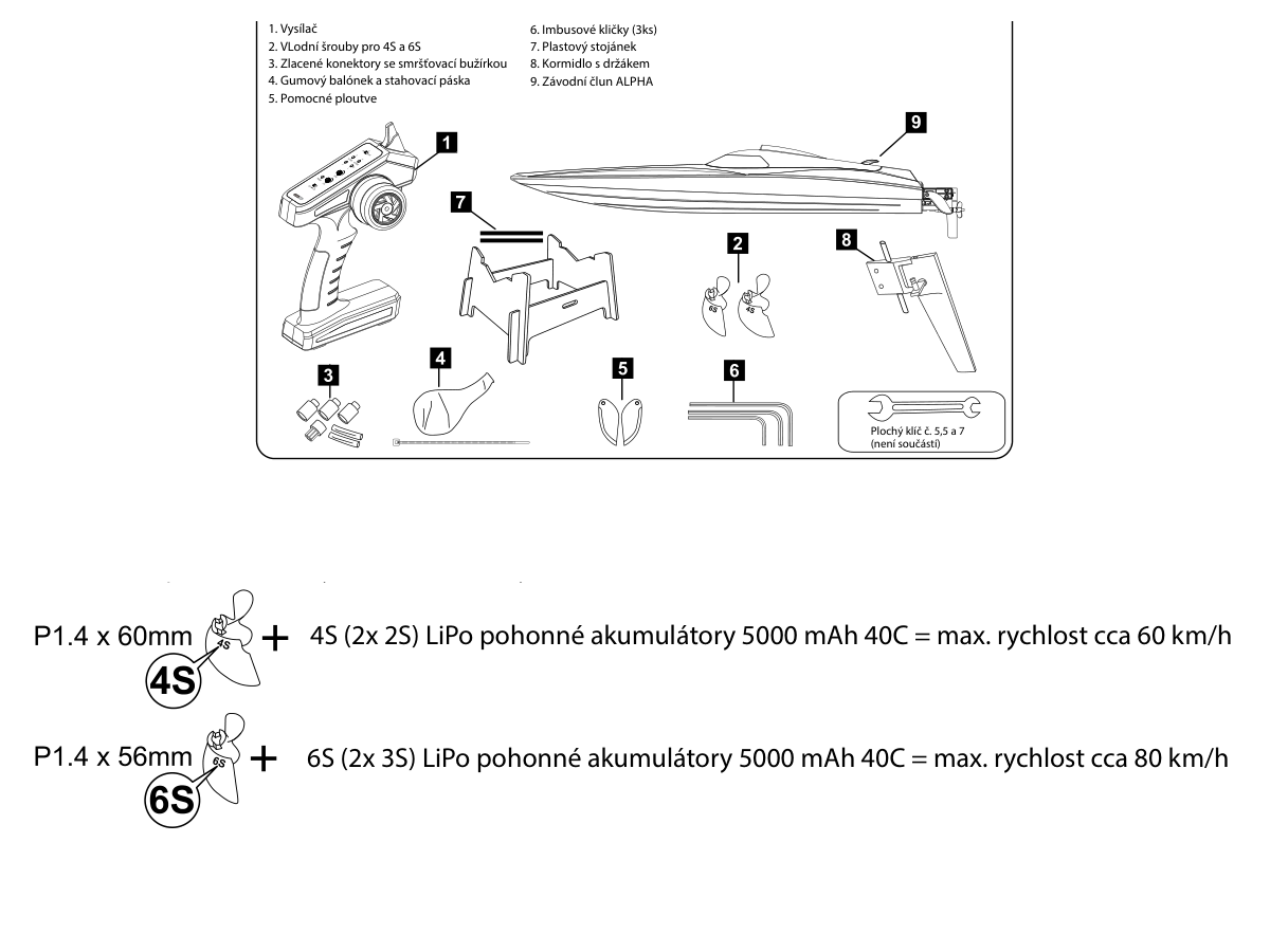
| 4S | 2× 2S 7.4 V; ≥5000 mAh; ≥40C | Ø60 mm × 1.4 | 60 km/h |
| 6S | 2× 3S 11.1 V; ≥5000 mAh; ≥40C | Ø56 mm × 1.4 | 80 km/h |
Match the propeller to the total cell count. The larger 4S propeller must not be used with 6S: motor and ESC overload can result. Use matching charged packs in the existing series harness, not parallel wiring. Charge each pack with a LiPo balance charger appropriate to its individual cell count.
Safety notes
This is not a toy. Users under 14 require close adult supervision. Range-test before every run, keep clear of the propeller and sharp metal parts, and allow hot equipment to cool before touching it. Disconnect both packs before drive maintenance.
Use this model only in fresh water, in an open area away from swimmers, people, animals and aquatic plants. Do not operate in confined water, rain or thunderstorms. If lightning or thunder occurs, stop operating and disconnect the model safely.
Never enter deep water or a strong current to retrieve a model. If control is lost, first raise the transmitter to try to restore the link. Use a safe recovery method from shore; do not put yourself or anyone else at risk.
Charge outside the model under adult supervision, on a nonflammable surface. Do not leave charging unattended. Use only the correct charger for the battery chemistry and cell count. Never short-circuit, dismantle, crush or burn a battery. Stop using a damaged, swollen or abnormally hot pack. Disconnect it after use and recycle exhausted batteries appropriately.
Contents and tools
Check boat with installed drive and servo, radio if included in the package, the 2 propellers, battery connectors with insulation, receiver balloon and tie, turn fins, 3 hex keys, stand and aluminium rudder with support. Add 5.5mm and 7mm spanners, 4 AA transmitter cells where applicable, the 2 selected LiPo packs and their balance charger. Ask a competent modeller to solder connectors if needed, observing polarity and insulating every connection.
Set contents and separate 4S/6S propellers. (Fig. 1)
Main section
Assembling the stand
Assemble the stand and glue its joints with medium cyanoacrylate or epoxy. Allow full cure before loading it. Fit the split rubber-tube pads to the upper supports to protect the hull.
Rudder, propeller and turn fins
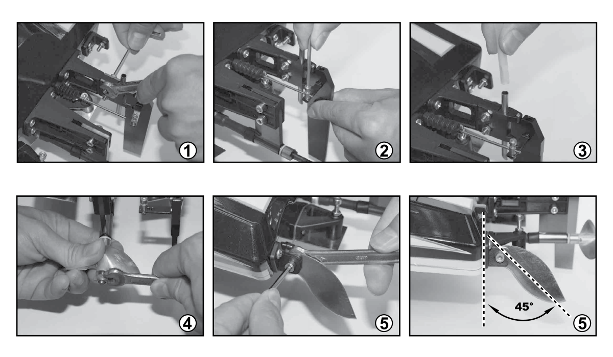
- Keep both drive packs disconnected. Slide the rudder assembly into its hull mount and secure with the 2 bolts and nuts using a 3mm hex key and 5.5/7mm spanner.
- Feed the rudder pushrod through the arm connector. Centre the servo with the radio on, align the rudder straight and tighten the connector with the 2.5mm hex key. Disconnect power before continuing.
- Push the cooling tube from the right rear hull onto the water-inlet nipple on the rudder. Fit the correct propeller and secure with the nylon-insert locknut. Tighten firmly without overtightening.
- Fit the adjustable turn fins to their stern mounts using the 3mm hex key and 5.5/7mm spanner. Start at 45° to the hull, as illustrated.
Shaft-strut angle and trim tabs
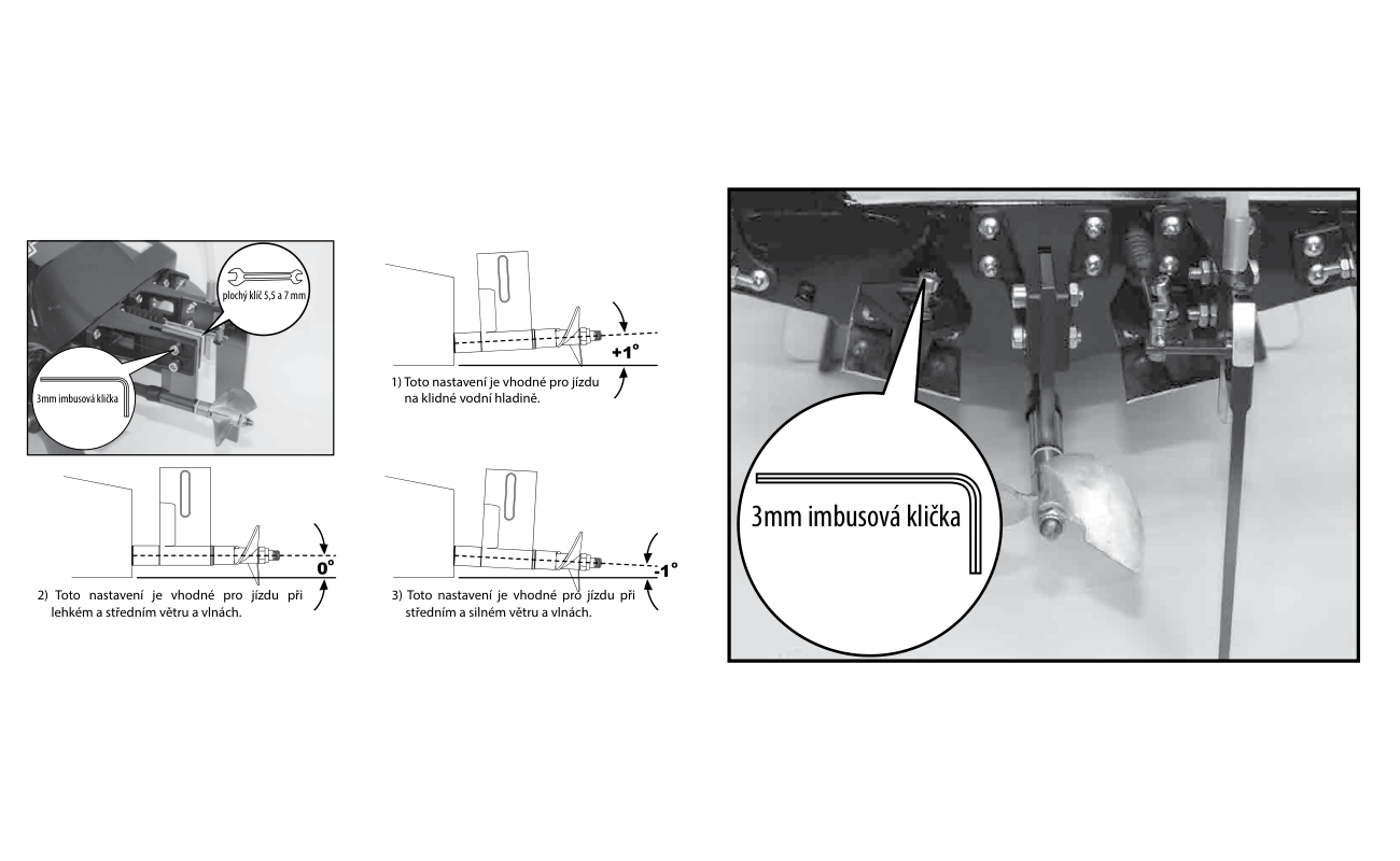
| Water condition in source | Shaft angle |
|---|---|
| Flat water | +1° |
| Light to medium wind/waves | 0° |
| Medium to larger waves, within safe conditions | −1° |
Adjust the strut with the 3mm hex key and 5.5/7mm spanner. Raising the shaft can increase speed but reduces steering response; too much causes cavitation, vibration, reduced speed and possible motor/ESC damage. Lowering improves steering but may cause oversteer and reduce speed. Make small changes and test each one.
Do not race in strong wind or large waves despite the comparative adjustment diagrams. Reduce speed before turning.
Trim tabs set running attitude, lateral list and the speed at which the boat planes. Factory setting is level with the hull bottom, 0°. Turn the adjusting screw with the 3mm hex key and secure its locknut. Lowering a tab pushes the bow down. Keep adjustments within 3°, change only a little at a time and observe handling.
Lubrication and water protection
Protect the receiver in the supplied balloon, tied around the leads. Keep the flex shaft greased: grease both reduces wear and seals against water entry. Lubricate shaft and tube every 2–3 h of operation; after intensive use, service at the end of each operating day.
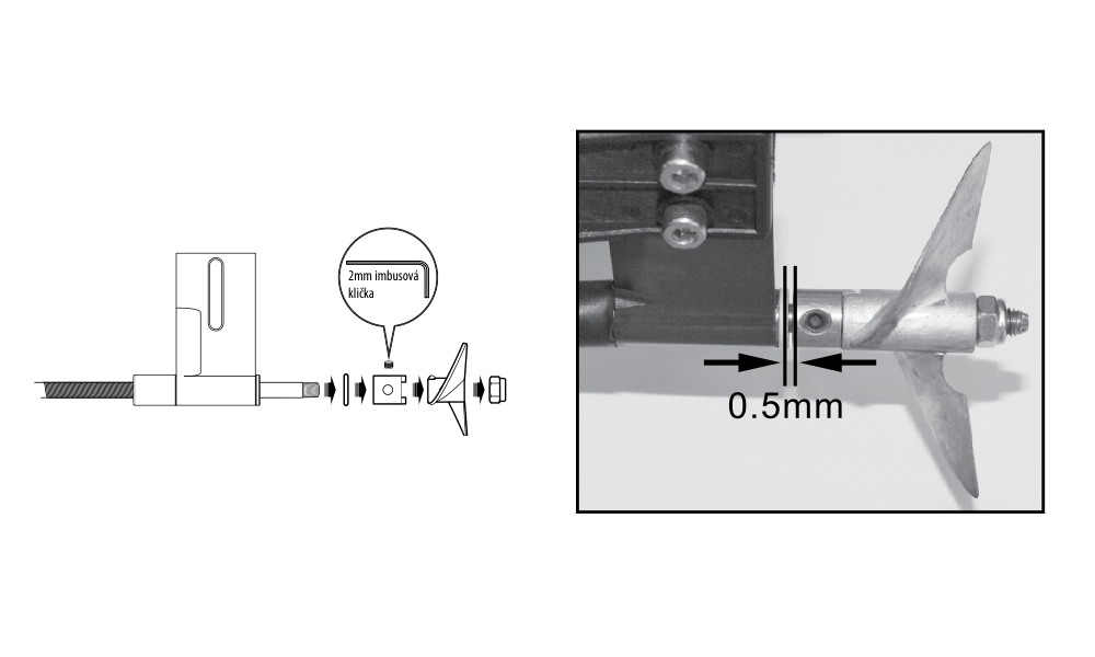
- Disconnect both packs. Loosen the motor-coupling grub screw with the 2mm hex key. Remove the propeller nut, propeller and washer as needed, keeping their order, and withdraw the flex shaft from its tube.
- Wipe the shaft clean, dry the inside of its tube and apply waterproof marine grease to shaft and bearing surfaces. Reassemble in reverse order. Leave the illustrated 0.5mm axial clearance at the propeller support/washer and drive dog before tightening the coupling; lack of clearance overloads the drive.
Battery placement and startup
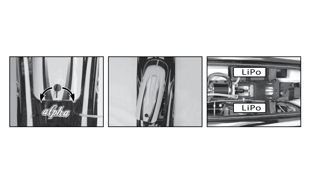
- On the stand, turn the hatch latch and lift the upper deck. Keep both drive packs disconnected while fitting them. Inspect all cooling hoses for kinks, loose joints and blockage before closing. Place one pack on each side of the hull as shown in the original Alpha drawing and secure both with hook-and-loop straps. Use the fitted gold-plated connectors with correct polarity; do not transfer the V2 battery placement to this hull.
- Switch the transmitter on at neutral throttle before connecting the packs to the ESC. With a BEC-equipped ESC, the receiver is powered by the ESC lead; no separate receiver battery is needed. Complete radio and drive checks, then refit and lock the upper deck.
Fit 4 AA alkaline or NiMH cells in the transmitter with correct polarity. Its red power LED must light when switched ON. Keep the transmitter dry. Seal the hatch perimeter with clear waterproof tape after checks and before launching.
Binding and startup
The RTR radio is normally bound at the factory. Bind again only if necessary: a red receiver LED indicates no established link.
- Keep transmitter and receiver within 1 m, with no other active 2.4GHz transmitter within 10 m. Keep the throttle at neutral and switch on the transmitter first.
- Connect the drive battery to the ESC, which powers the receiver. Press the receiver’s BIND button. A steady green LED confirms binding. If green continues flashing, repeat the procedure.
- At normal startup, wait for the ESC’s 3 beeps before checking controls. When stopping, disconnect the boat battery first and switch off the transmitter last. Never leave a drive battery connected when the boat is not in use.
Checking direction, trims and travel
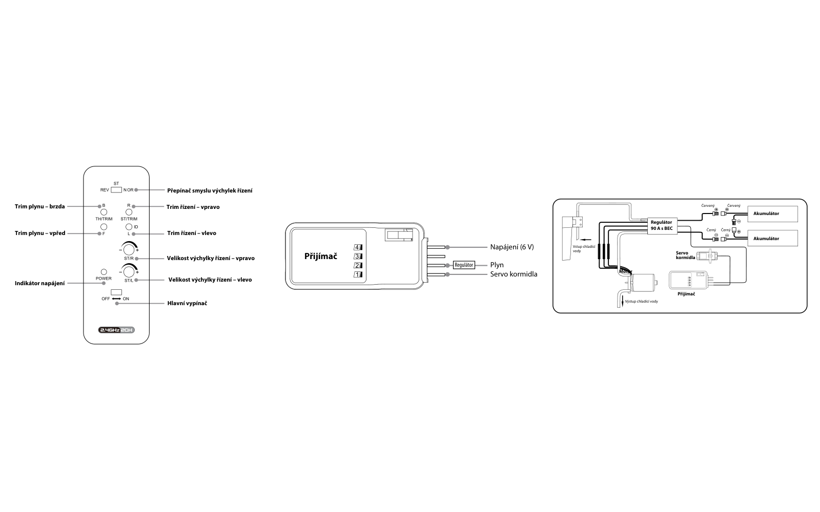
- With the boat supported and the propeller clear, turn the steering wheel right. The rudder’s trailing edge must move right; a left command must move it left. Correct a reversed response with ST REV/NOR, then recheck.
- Use ST/TRIM R/L to centre the rudder. Fine-adjust it on the water so the boat runs straight with the wheel centred.
- Set TH/TRIM B/F so the propeller stops with the trigger released. Briefly pull the trigger to check motor response; keep this dry check short because water cooling is not operating.
- Adjust right and left steering limits separately with ST/R and ST/L. Each knob covers 0–100 %: fully left is 0 %, fully right is 100 %. Start with the factory settings and reduce travel if needed; the servo must not force the linkage against a stop.
Viewed from astern, the propeller must rotate anticlockwise when forward throttle is applied. Keep any dry motor test brief because water cooling is inactive. Check steering and radio range before launching.
Original 90A ESC throttle calibration
Remove the propeller and secure the boat before calibration. Keep the motor connected for the audible signals and remain clear of the drive.
- Before first use set throttle travel to ±100 %. With a Futaba transmitter, set throttle direction to REV. Switch the transmitter on and select full throttle.
- Connect the packs to the ESC. After 2 s, the double beep confirms full-throttle storage. Move the trigger to motor stop/neutral; a long beep confirms storage. Disconnect power before refitting the propeller.
Running and low-voltage protection
Inspect every cooling hose and water inlet before launching. Remove blockages and replace damaged or kinked tubing; loss of cooling can damage the motor and ESC. Start near shore and increase speed progressively. Return as soon as maximum speed begins to fall.
The ESC stops the motor at 3.2 V per LiPo cell. If this happens, return the trigger to neutral to reset, then use only enough power to return slowly to shore. End normal runs before cutoff. Repeated resets can deeply discharge and permanently damage the battery.
If the boat starts bobbing unusually, water may have entered the hull. Return immediately, disconnect the battery, remove the hatch and drain and dry the hull.
Running time and cooling
The original Alpha source gives about 4 min per charged set, depending on batteries and driving. Return as soon as speed falls. Allow 5–10 min cooling before fitting another set to prevent overheating and premature motor wear.
After use
- Disconnect both drive packs before switching the transmitter off. Remove the model batteries and transmitter cells for storage.
- Wipe out water and leave the upper deck off in a warm, dry place until the hull is completely dry. Temporarily remove the receiver from its protective balloon to dry it, then restore its protection before the next run. Maintain shaft lubrication regularly.
Troubleshooting
| Problem | Remedy |
|---|---|
| No movement | Install missing batteries, check connections and polarity, replace/recharge transmitter cells and recharge drive packs. |
| No control or short range | Replace/recharge weak transmitter batteries and recheck radio operation before relaunching. |
Appendix
Recycling (European Union)
Electrical equipment bearing the crossed-out bin symbol must not be disposed of in normal household waste. Instead, it must be taken to a specialised collection and recycling facility. In EU (European Union) countries, electrical equipment must not be disposed of in normal household waste (WEEE - Waste of Electrical and Electronic Equipment, Directive 2012/19/EU). You can take unwanted equipment to your nearest collection or recycling centre. The equipment will then be disposed of or recycled safely, free of charge. By handing in your unwanted equipment, you can make an important contribution to protecting the environment.
EU Declaration of Conformity
Joysway Hobby International Ltd. hereby declares that the model Alpha and other equipment supplied with it are in compliance with Directive 2014/53/EU. The full text of the EU Declaration of Conformity is available at the following website: https://www.kavanrc.com/doc. This 2.4 GHz radio equipment can be used without prior registration or individual approval in all countries of the European Union.
Warranty and post-warranty service
All Joysway products are covered by a 2-year warranty covering all manufacturing defects and faults. When making a claim within the warranty period, please always present a copy of the proof of purchase with the product and provide the service personnel with as detailed and complete information as possible about the defect found, your usage and other information that will facilitate the assessment of the claim and speed up its settlement. Please make your claim at the shop where you purchased the product.
This warranty certificate entitles you to a free warranty repair of the product supplied by KAVAN Europe s.r.o. within a period of 24 months. The warranty does not cover natural wear and tear due to normal use, as this is a product for modelling use, where the individual parts operate under much higher loads than normal toys are subjected to.
The warranty also does not cover any part of the equipment that has been improperly installed, roughly or improperly handled, or damaged in an accident, or any part of the equipment that has been repaired or altered by an unauthorised person (this includes the application of any waterproof sprays/coatings by the user). Like other fine electronics products, do not expose this equipment to high temperatures, low temperatures, moisture, dusty environments, violent mechanical shocks and impacts. Do not leave it in direct sunlight for extended periods of time.
Improper installation includes inadequate mounting, mechanical strain on cables and insufficient cooling.
Please claim warranty repairs from the shop where you purchased the product.
If possible, use the original packaging when returning the product for service. Include a dated description of its use and the fault, together with your full address and telephone number.